Duct Tape E-Bay Lifepo4s???

karma said:
i was thinking on doing that, what are the fets rated at? Doesn't the + out run threw the fets?

Right, the current still goes through the FETs so you don't want to exceed their rating. If the Ping BMS was rated for 40 amps, then use a 40 amp fuse. A fuse will allow a higher current for a very short time.

phenomatuan said:
Hi Guys,
Yes, I intend to run the packs in series and I've got a cycle analyst. I'm getting 2 schools of thought in regards to protection: using diodes (as in Schottky Diodes?) vs. LVC Boards. I really dont know the advantage of one over the other.

If you're using the stock BMS, then it already has a LVC built in. You just need diodes.
The diodes are only there to protect the BMS against overvoltage if the other one trips.
The diodes can be regular diodes, but need to handle the full amp and volt rating of the battery. The diodes go across the wires coming out of the BMS (to controller).
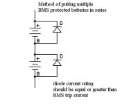
BMS in series config.jpg
 
I have exactly the case where I will have 2 -36V packs in series, one pack is 10ah and the other is 12ah. Switches would be simpler, but one would have to make sure the LVC does not let the battery cut back on.

Otherwise you would have a dead short when it kicked back in. Any type of switch that would disconnect the battery as it connects the parallel jumper?

What this city needs is a diagram...

DK


Deepkimchi said:
I have exactly the case where I will have 2 -36V packs in series, one pack is 10ah and the other is 12ah. Switches would be simpler, but one would have to make sure the LVC does not let the battery cut back on.

Otherwise you would have a dead short when it kicked back in. Any type of switch that would disconnect the battery as it connects the parallel jumper?

What this city needs is a diagram...

DK

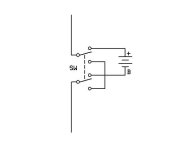
To bypass one battery, you would need a DPDT switch that can handle the full current.

battery bypass switch.jpg
 
Deepkimchi said:
I have exactly the case where I will have 2 -36V packs in series, one pack is 10ah and the other is 12ah. Switches would be simpler, but one would have to make sure the LVC does not let the battery cut back on.

Otherwise you would have a dead short when it kicked back in. Any type of switch that would disconnect the battery as it connects the parallel jumper?

What this city needs is a diagram...

DK

Actually, since the 10Ah pack has a higher "C" rating than the 12Ah, I'm guessing the actual capacity used in both packs, with both in series, might be fairly close. It depends on how big a load you put on the system. If you have some moderate hills in your normal commute, the voltage drop under load for your existing pack is going to be greater than it will for the LiFeBatt-based pack. That means a bit higher "burn rate" for the 12Ah pack. My point is that if you run the LiFebatt 10Ah pack down to cutoff, which is perfectly fine (I do it all the time, almost evertime I ride...), there's not going to be much left in the existing 12Ah pack to make it worthwhile worrying about a switch setup. You are still going to get double the range you were before with just the single 12Ah pack, mainly because running at 72V total, means the packs only half to supply half the current , to handle the same loads, and less current means less heat losses, in the motor and in the packs. Heat losses go up as a square function of the current, so higher voltage and lower current is always a good thing. The problem is that in reality, you will find it extremely difficult to now make use of all that extra power that you will have available, so your chances of actully achieving double your existing range are pretty remote. :mrgreen:

Anyway, I'd just connect the 10Ah first in series, so that its negative power lead is the main negative lead for the system. Connect the plus of this pack to the negative lead of your existing pack, and its positive lead becomes the main positive lead going to the rest of the system. You could add a diode across the +/- leads of the 12 Ah pack, as Richard has shown, but I wouldn't bother with a diode for the new 10Ah pack.

-- Gary
 
http://cgi.ebay.com/36V-15A-Electric-Scooter-E-Bike-Bicycle-LiFePO4-Battery_W0QQitemZ220230828409QQihZ012QQcategoryZ11332QQssPageNameZWDVWQQrdZ1QQcmdZViewItem

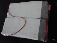
What do you think this battery is made of. It looks like chewing gum!
duct.jpg
 
Yeah, you're right. Right now the round trip to work only uses about 6 ah. I can't go more than 40 kph (25 mph) thru town (Koreans tend to pullout or walk out in front of you). On base there's only one back road where I can really open it up.

Main thing will not having to creep up the hills at 28 kph. I'll hold on the switch for now.

DK
 
Just a head's up, I just got word from Ping that they're short on stock for the next 4-7 weeks. So the packs on e-bay will be the only ones available during that time.
 
Just got a 48V 20AH battery from Ping. The guy is amazing- because of the security checks in China the EMS shipment was a week late, and Ping paid out of his own pocket to ship to me using UPS Express. I got the battery in just one day! The guy truly is a man of his word- he promised to ship by May 10, and he did it. He ships exactly when he says he will, he always replies to queries and has a good command of English.

Unlike Anna...

With Anna, the experience was a total nightmare. I didn't receive the battery in 2 months (and still haven't), while the guy spoon-fed me promises and just plain lied to me. In the end, I opened eBay and PayPal disputes against him as I still don't have either the battery or the money, while he keeps lying that he'll refund me tomorrow, then day after tomorrow, then next week, etc. The guy is a liar, a crook and a thief. He is no longer a registered member on eBay- seems like he has run with his clients' money...

Anyhow- Ping rules.
 
Hello Everyone,
Unfortunately while I was riding a couple of days ago the motor suddenly cut off on me. I saw smoke coming out of the battery bag :shock:, and originally thought that the BMS had blown. What happened was that the electoral tape on the BMS (I replaced the duck tape which was in direct contact with the FETs because it started to melt when charging) started to overheat and catch fire :( .Is the blue "plastic" that is on top of the BMS ordinary heat shrink? Fortunately it melted the connection of one the FETs legs and cut connection to the motor before there was any explosion.

The voltage still reads 53.7V if I connect the negative lead to the FET leg (or other FET legs), however if I connect it the negative output (or FET body) it reads 47.6V :? ? The Doc Wattson showed a AP of 28.7A, at 53V (48V/15Ah Battery). Will it affect the source/drain ability if I connect a metal tab from the broken leg to the FET metal ring by bypassing the body (it showed 53.7V and the lights lighted up on the controller)?

What are the FETs rated at if I were to look at replacing them?
IMG_2709.jpg

IMG_2707.jpg
 
If the FET was heating up during recharging to the melting point, then something was badly wrong with the board from the beginning.

Ask the vendor for a replacement.
 
Hi folks,
I am glad I found this forum, and I hope you can help me.

I bought a 36V 10AH from Ping recently and thought I got it connected right, but maybe not. The package looks like the pictures I have seen here--a duct tape battery with three wires coming out, and a charge with a circular end and three protruding ends for positive, negative, and null. I charged the battery by sticking the wires to the protruding ends correctly and got the batter charged. I was confused how to connect it to the e-bike (I have an EVG ebike) at first, then decided to use crimped ends from radio shack and connected the wires that way (positive and discharging negative to red and black, respectively).

The bike ran fine for two days or so. The power disconnected on steep slops and I had to disconnects and reconnects to get it going again. I noticed a "big" spark every time I did this and then the bike comes to life. There must be something wrong.

Sure enough, now the power disconnects with very minimum resistance. If I am holding the bike in place and press the throttle, the power goes out and I have to disconnect/reconnect, and again with the spark. The spark actually causes the crimped ends to have black spots on them, so I guess it's not normal.

Please help. I have read that you need to soldier the wires from the battery? soldier them to what? Am I missing any pieces that were supposed to come with the package? Am I missing something on the connection?

Thanks
 
Ranger said:
Hi folks,
I am glad I found this forum, and I hope you can help me.

I bought a 36V 10AH from Ping recently and thought I got it connected right, but maybe not. The package looks like the pictures I have seen here--a duct tape battery with three wires coming out, and a charge with a circular end and three protruding ends for positive, negative, and null. I charged the battery by sticking the wires to the protruding ends correctly and got the batter charged. I was confused how to connect it to the e-bike (I have an EVG ebike) at first, then decided to use crimped ends from radio shack and connected the wires that way (positive and discharging negative to red and black, respectively).

The bike ran fine for two days or so. The power disconnected on steep slops and I had to disconnects and reconnects to get it going again. I noticed a "big" spark every time I did this and then the bike comes to life. There must be something wrong.

Sure enough, now the power disconnects with very minimum resistance. If I am holding the bike in place and press the throttle, the power goes out and I have to disconnect/reconnect, and again with the spark. The spark actually causes the crimped ends to have black spots on them, so I guess it's not normal.

Please help. I have read that you need to soldier the wires from the battery? soldier them to what? Am I missing any pieces that were supposed to come with the package? Am I missing something on the connection?

Thanks
Hi ranger welcome to the club lets get some basics out of the way first please excuse the list method
1 what have you in the way of meters a wattsup is the minimum you should realy have.
2 what were the old batteries on the bike if any?
3 get a good set of heavy duty connectors for the power connections and any cables should be heavy duty as well.
4 you want a automotive fuse holder and a heavy duty(16a) switch between the battery and the controller on the positive line, with that size pack get 20 or 25 amp fuse should be plenty.
5 change or clean all blackened connections.

lets see If we can get you going and enjoying your new battery.
 
Hi Geoff,
Thanks for the reply. Please excuse my lack on knowledge in this; I have never done this before:

1 what have you in the way of meters a wattsup is the minimum you should realy have.
I have nothing other than the ebike panel with green, yellow, and red lights measuring how "full" the battery is. I looked up watts up after your comment and this is what I found:http://www.amazon.com/ELECTRONIC-EDUCATIONAL-DEVICES-Watts-Meter/dp/B0004HJP8W/ref=pd_bbs_sr_1?ie=UTF8&s=office-products&qid=1210603386&sr=8-1

It doesn't look like something that would easily fit on the bike though. Do you guys have something else?

2 what were the old batteries on the bike if any?
They were SLA 24 volt. I read in another website that the motor and controller on EVG ebike can handle the 36V upgrade

3 get a good set of heavy duty connectors for the power connections and any cables should be heavy duty as well.
The only connectors I found in the local store radioshack were these: http://www.radioshack.com/product/index.jsp?productId=2104019
Do you recommends anything different?

4 you want a automotive fuse holder and a heavy duty(16a) switch between the battery and the controller on the positive line, with that size pack get 20 or 25 amp fuse should be plenty.
Where do I get this from? Also, the controller has only a positive (red) wire that I connected to the positive battery with the possitive motor wire. I was wondering why there is no black wire from the controller. Please excuse my ignorance. Could that be the reason for the spark?

5 change or clean all blackened connections.
I will, thank you.
 
Oh by the way, doesn't the BMS that comes with the battery have a fuse inside? Do I still need an external fuse?

The ebike has the following wires: psitive and negative from motor, positive from controller, and positive and negative from the horn. I have all 3 positive connected to the battery positive and the 2 negatives to the battery discharge negative.
 
I just found the manual for the EVG ebike online: http://ilbcnu.org/file_share/evg_ebike_24v_service_manual.pdf Still can't figure it out
 
The BMS has a 40 Amp cut off ... exceed 40A, and the BMS shuts down and must be reset. Yes, you need to pedal going up hills with most motors.

The sparks are caused by using poor connectors. Get either Anderson Power poles, or Dean's RC connectors for your main power.

The main leads from the Battery should go to one, and the controller main leads to the other. ( Other items that require power will need a transformer if they are low voltage, otherwise the battery will fry them. )

( As for the charger: OK ... you have three wires from the battery. A large Positive, a large negative, and a small negative charger. Then get an XLR connector that matches the charger, and send the small charger negative to that, and a small splice off of the large battery positive. )
 
kbarrett said:
The sparks are caused by using poor connectors. Get either Anderson Power poles, or Dean's RC connectors for your main power.

The sparks are caused by the controller's large capacitor's charging up. Good connectors will still succumb to the sparks eventually. Bad/lazy/cheap controller design -- except they all do it. There are various work-arounds.

I use a switch with a 1K, 10watt resistor across it. Making sure not to leave it hooked up overnight. An active cutoff BMS with a switch incorporated would be ideal.

Richard
 
rf said:
kbarrett said:
The sparks are caused by using poor connectors. Get either Anderson Power poles, or Dean's RC connectors for your main power.


The sparks are caused by the controller's large capacitor's charging up. Good connectors will still succumb to the sparks eventually. Bad/lazy/cheap controller design -- except they all do it. There are various work-arounds.

I use a switch with a 1K, 10watt resistor across it. Making sure not to leave it hooked up overnight. An active cutoff BMS with a switch incorporated would be ideal.

Richard

I stand corrected. But poor connectors won't stand up to the abuse for long.

I also use a key switch, and use that to turn the battery "on", so my Andersons don't take a beating. I consider it expendable ... at some point the voltage surge going into it is going to wreck it ... but I can get a large amp tractor ignition switch for $12 at a feed store ... so it isn't a big deal.
 
Hi all
the largest key switch Icould find was not up to the job so I use 16a automotive switches all adds up to the same thing.
just looked through the manual pdf looks like a dc heinzmann motor check out page 52 fig 8.
how sure are we that the controller can take 36v I havn't had a lot of dc motor work.
 
kbarrett said:
The main leads from the Battery should go to one, and the controller main leads to the other.
Hi,
What do you mean? I have one red wire from the controller and two (red and black) from the motor
 
geoff57 said:
Hi all
the largest key switch Icould find was not up to the job so I use 16a automotive switches all adds up to the same thing.
just looked through the manual pdf looks like a dc heinzmann motor check out page 52 fig 8.
how sure are we that the controller can take 36v I havn't had a lot of dc motor work.

Please explain why we need a switch between the battery and the bike. The original SLA pack did not have a switch.

Do I need to install an external fuse? Is that not already in the BMS?
Thanks,
 
Ranger said:
kbarrett said:
The main leads from the Battery should go to one, and the controller main leads to the other.
Hi,
What do you mean? I have one red wire from the controller and two (red and black) from the motor

Hokay ... now I'm confused. I assume the motor is a brushed DC. Standard procedure is to plug the batt into the controller, and then the controller into the hub motor ... unless you are using some kind of common grounding scheme.

Could you post a pic of the controller?

( reason for a switch is to avoid eroding your connectors ... you hook stuff together with the power off )
 
I'm going to ask that this thread jack get forked off to another thread ... might need a bit of attention, and not related well to ping packs.
 
Back
Top