EMC-2000 charger from ecity (1500 to 2000W)

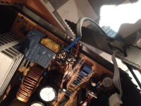
no, just as a test i stuck in another smaller one I had kicking around,

original is GBJ 2510
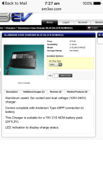
 
25A1000V is about right. the leg spacing changes as you go up in size too so keep that in mind for replacing it. but go ahead and order that online and test the IGBTs like i said and if you find one is bad then order two to replace both of them or even maybe order 4 to replace all of them if you can see anomalies in the forward bias when using the diode tester between the collector and emitter. also there should be infinite resistance between collector and gate, emitter and gate.

i can look up the guy i bot my IGBTs from for $4. mouser is $13 as i said in the pm. the rectifier will be a lot more from mouser too than off of ebay but the same source as the IGBTs may have the rectifier, and he is cheaper and only the one $4 shipping charge for multiple parts on the same order.
 
I tend to use RS Export for my orders as they give free postage to Jersey..or Farnell, as I have account with both companies..and they are quick, generally 1-2 days

These are these: GT50J325

I'll pop those IGBT's out and test them as per

[youtube]AfV7gYChILc[/youtube]
 
the top one is from utsource where i bot mine:

http://www.ebay.com/sch/sis.html?_nkw=GT50J325+Manu%3ATOS++Encapsulation%3ATO-3PL%2CTOSHIBA+Insulated+Gate+Bipolar&_id=110886765344&&_trksid=p2057872.m2749.l2658

i will look for the rectifier too since he includes everything in the one $4 shipping.

http://stores.ebay.com/UTSOURCE-STORE/_i.html?_nkw=gbj2510&submit=Search&_sid=1084113345
 
Thanks for those links

In circuit testing , in both forward and reverse bias across the C-E in diode mode, there is zero voltage drop on all four ,

SO ordering them up is the first step I suppose. Though, since that is the output side..would the unit power on if those are just removed and left out for now?

At the moment, because they are shorted, I can't power it on , so the Red LED display does not come on. Just wondering if the switching side of the board and the LED display will power up if those IGBT's are not present. no point spending a load of money on new parts if the drive side is also toast.

EDIT :
got an order sorted..on e-bay thanks for the link
 
i would recommend ordering 4 of them if they all tested with 0V across the pn junction in both directions.

order rectifier and IGBTs together from utsource. he is in singapore as i recall and it will be there in three days. maybe even go through his store and look for other stuff you like.

before powering up you can go reset the trimpots to the middle of their range. use your ohmmeter and follow the resistance as you twist the trimpot from one end to the other. they are all 10 turn i think. you should see the resistance swing from one end to the other when you measure across the outside pins. set them in the middle to restart.

did you twist all of them or just a few? if you never touched one, don't change it now. just the ones you twisted already. it is hard to feel the end spot where the wiper is jumping on the screw and doing that while powered up can cause voltage spikes too. in the circuit.
 
Just the current , but I can't remember which way was 'up'. I seem to remember that it was not conventional, but can't be sure.


The issue was, I think, that i probably adjusted it up, after it had left the CC mode. Current increased, but it meant that when i put a full discharged battery on, it went way over the top ...

At least that is a best guess

got 4 on order, so just have to wait now
 
i suspect this will make it work again. cheaper than just one part from mouser. shipping is what eats me up. if i ordered $400 in parts it would not matter but when you order a few small items and the shipping costs more than the parts it is so so annoying.
 
Order, arrived and repaired.


One thing to note.

The voltage pots work in reverse sense.
You turn them ANTICLOCKWISE to INCREASE Voltage

I believe that current is the same too..but did not write it down to confirm


Doctorbass said:
I bought it and received it a week ago.

i'll try to review it and make some modifications to it.

I communicated with Jack Xie to confirm the adjustment potentiometer inside

W503 is for voltage
W401 is for end of charge current cut off adjustment
W402 is also for current adjustment ( probably the fine or coarse)
W4011 is also for voltage adjustment ( probably the fine or coarse)
W501 is for LED lamp indicator ajustment.

I had succed to adjust it to 12V to 105V and keep it stable.


Doc

Current pot W401 that DrB says is End Of charge current...ummm...not sure ...i found it DID change current at beginning of charge too. so it may well as is implied in the writing for W402 that one is for fine and one is coarse. OR it is just that end of charge current adjustment also affects the main charge current
 
This tread is great,nice work doc
Can the 1k resistor be put on this charger so to give an output voltage ?
 

Attachments

  • IMG_0750.JPG
    IMG_0750.JPG
    67.5 KB · Views: 1,925
  • IMG_0751.PNG
    IMG_0751.PNG
    58.3 KB · Views: 1,925
Earlyer on in this tread doc talked about putting a 1k resistor across the output relay so the charger thinks theres a battery present,then its possable to adjust output voltage without a battery plugged in,?
 
oh right, OK,
not tried it, but ...umm I won't comment...as I have not tried it with this one..but online way to find out
 
Got a tiny problem with this charger - it stopped charging the other day.
It displays voltage but not sending current to the batteries - checked the fuse at the on/off switch and connectors - all good. Wondering about the next step to trouble-shoot.. Is there an output fuse somewhere inside that might be the problem?
https://goo.gl/photos/BN2G1nX7w8ESF4yM7
 
Do you have an electrical tester? You really need one to to sort this kind of thing out, an inexpensive one is all you need. simple checks first, faults can often be simple and hopefully yours is.
unplug the charger.
Try simple continuity
First check the positive battery wire - check from the pin on the charge pin back to the end of the cable where it connects to the circuit board.
second check the negative battery wire - check from the pin on the charge pin back to the end of the cable where it connects to the circuit board.


wojtek said:
Got a tiny problem with this charger - it stopped charging the other day.
It displays voltage but not sending current to the batteries - checked the fuse at the on/off switch and connectors - all good. Wondering about the next step to trouble-shoot.. Is there an output fuse somewhere inside that might be the problem?
https://goo.gl/photos/BN2G1nX7w8ESF4yM7
 
Back
Top