Parallel packs feedback.

Lammy

10 mW
Joined
Feb 12, 2023
Messages
20
Hello all, I have been plodding away with a conversion project for an old Lambretta for a while. As was expected the challenge has been packaging everything within the space available. I have a battery layout i would like to put up here for any thoughts and feedback.
The preferred specification I have for the pack is 72Volts with a capacity of 60Ah, I would also like to achieve a high enough output current to be able to run the pack well within its limits to prevent overheating and to maintain healthy cell chemistry.
To achieve this, due to space constraints I will need to split the pack into 2.

The options for this as I understand are:

1- connect the 2 packs as 2 stes of 10S x 12P packs - this would require a connection cable capable of handling the current running in series between the 2 packs and also balance cable connections to be made to a central BMS. - This strikes me as possibly a complicated set up to achieve.

2 - have 2 separate 20S x 6P packs with their own BMS with a switch to change packs. - It will leave me a little under rated on output, meaning that under load the cells will be pushed harder than I would like.

3 - connect the 2 packs in parallel each pack to have its own BMS. this is my preferred option as it will give me the best capacity and output, but obviously comes with some challenges.

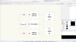
I have a schematic of how I would like to construct option 3, which I have attached.
The first schematic shows the system as it would be in operation the controller is an ASI BAC 8000, I have added a battery disconnect switch with a precharge circuit as well as 150A fuses per pack.
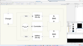
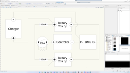
The second schematic shows a possible parallel charging circuit.
Thanks in advance for any thoughts.
 

Attachments

  • Screenshot (81).png
    Screenshot (81).png
    489.8 KB · Views: 14
  • Screenshot (80).png
    Screenshot (80).png
    506.2 KB · Views: 14
I've mentioned it elsewhere, but I run two 52v packs in parallel. One is a Luna Shark pack (14s4p) that has two XT90 outputs. One of those goes to the controller and the other is directly wired to the other 52v pack (14s5p) that has it's own 2-wire BMS. When connected I only charge to 90% (through the XT60 on the Shark) but separate them once a year and charge to 100% for balancing. On its fifth year with about 6,000 miles on the setup (BBHSD). Simple setup that has worked extremely well but each to their own. Just say'n......
 
In my opinion, #3 is relatively safe for single user. Odds are nothing bad will happen. If a scooter seller tried this with 10000 units, maybe one or two would probably fail when one of the batteries got unbalanced. In other words, it will work til it doesn't. A y-connector with diodes in it would be a good idea as long as the diodes never failed. They sell these things, but until they get UL ratings, who knows,

Another approach is two self contained 10S packs in series, but both have a BMS that can hold off 100 volts. I don't know where you find that BMS. Maybe use the BMS to control a high current relay. The risk of two packs in series is that if one BMS goes open circuit, its MOSFETS's have to withstand the voltage from both packs.

There was one poster who put two 13S in series (108.8 volts max), and the theory became real when one battery BMS blew up with the MOSFET's short circuited. He lost his protection, and more bad things eventually happened and the pack caught firew while riding.
 
Thanks everyone really helpful. I realise I was a bit light with my detail, I should have said, both packs will be "identical" as in newly built with new cells etc.

J Bjork, yes that is my ideal scenario as the BMS would balance all the P groups and charge through a single common port, my problem is I dont have a picture in my head how that would be acheived as a build.
Diggs, yes a lot of the feedback is maybe this is an overthinking excercise and that with a sensible management of charging and balancing this will be fine.
Doc I have considered a pair of one way diodes as a safety measure, my concerns were heat management and efficiency but I should look into that a bit more. The twin BMS in series worries me for the reasons described, at least twin BMS with common port charging have some capability to manage overvoltage.
 
4 - connect 2 packs in parallel with one bms. Takes a little more wiring.
This is a schematic as to how I understand a parallel packs single BMS setup could work, but the big question mark for me is how do the balancing leads work, effectively the BMS would need to be able to handle 40S?
Alternatively the BMS just balances the 2 packs as 2 x 72v cells which means there is very little management on a P group level and also thats a lot of balancing to manage?
Curious to see what you think.
 

Attachments

  • Screenshot (82).png
    Screenshot (82).png
    507.8 KB · Views: 7
For a 20s battery you only need a 20s bms, it dosent matter how many cells or packs you parallel.
You just parallel the balance wires and the negative and positive wires from each pack and connect to the bms.
It becomes one pack, it just happens to be split in two parts.

I would avoid separate fuses like you have in your picture if possible, and just use one fuse for all of it.
Bad things could happen if you blow one of them. Hopefully if your balance wires are thin you would only burn off them when a lot of current passes trough, or the bms trips when when cell 20 in the other half have to take a lot of more current than the rest of the cells.
Thanks, that makes sense, yes I can put a single fuse between the disconnect switch and the 2 parallel positive leads.
 
Back
Top