GT i-drive 2.0 Build

This is a really sweet bike. I really like it.

It's really close to what I'm halfway through building - I'll update the DH Team thread that Voicecoils started tomorrow.


What's all that white stuff on the ground? It will be 41 deg C here on Monday (106 deg F)....different world ;)
 
Fenders are key to riding in this slop! I picked up a DH bike off CL and got my rear 9c in place. Lots of room with the 6 inch wide drop outs and large bore rear wheel on this Giant Faith 2 frame. Lipos on the way from HC!

Dave
 
Mark_A_W said:
This is a really sweet bike. I really like it.

Thanks! Me too. :D

I was checking out your bike a while ago. Where's the thread for yours and the DH Team?

dbaker said:
I picked up a DH bike off CL and got my rear 9c in place. Lots of room with the 6 inch wide drop outs and large bore rear wheel on this Giant Faith 2 frame. Lipos on the way from HC!

6" wide dropouts? wow, nice! you got a thread-on disc on the rear 9C? You can have mine if you want as it won't fit my frame... Just looked up the Giant Faith. Where you gonna put the lipos? rear rack?

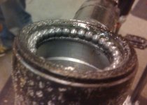
Update: I got the headset rebuilt tonight. Took it to a bike shop that deals in GT's. There was way too much play. Here's the before, all nasty dirty. Check out the salt all over the place...
2010-01-09 19.27.03_Washington_District of Columbia_US.jpg
Mechanic put in a new star nut, new bearings and tightened it all up. No more play. But for good measure, I ordered a new sealed headset, due to arrive in a week. I don't want to ruin the frame.

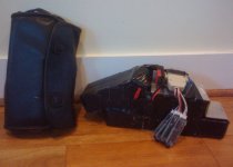
In other news, here's my temporary pack and my 'toilet-kit' charger. The pack is 8 5Ah lipo packs, wired up as 4 10Ah packs with the balance taps wired into a db25. It's shown here in discharge mode w/ power leads serialized and balance taps connected to 4 lipo buzzers, via db25:
2010-01-09 08.04.27_Washington_District of Columbia_US.jpg

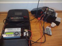
Discharge power and balance connectors removed and plugged in to charge (10A @ 5S)
2010-01-09 08.05.39_Washington_District of Columbia_US.jpg
 
The charging pictures make it much clearer for me now! Do you leave the buzzers on while riding or are they kept in the toilet kit? Do you worry about getting the batteries deformed by the frame as you are riding?

Keep an eye on your new torque arm. Most all of the arms I see (other than the 10mm end wrenches) are closed. I think you want to arrange a bolt through the edge of the torque arm to squeeze the slot you created against the axle flats. This would be optimum for cycling between regen braking loads and WOT acceleration!

Lookin' good!

Dave
 
Buzzers (BM6s) on while riding. They beep if any cell hits 3.3V. They're my 'BMS'.

I could leave them in while charging, but:

1. I've got a smart charger that does the balancing when I connect the balance leads, and won't even let me charge if everything isn't wired properly, and
2. the BM6's don't balance (like your battery medic).

Nevertheless, the BM6s would beep if any cell hit 4.2V (or whatever I/you set it to.)

Here's a diagram I made when I thought 60V would be enough for me.


I decided to wire the balance leads to & from the pack using DB25 connectors because:

1. Plugging and unplugging the JST-XH's is not fun. The edges are sharp, and I don't think they're made for daily use. Even still, I followed methods suggestion of running a bead of expoxy (CA Gel) around the wires where they go into the JST-XH connector, because they do loosen up.
2. I couldn't find long enough extensions to cut up and make the 5S charging extension and getting the charger close enough to the pack was awkward, meant hanging in the air while charging when the pack was on the bike.
3. The more connections, the more chances to make mistakes.
4. The DB25 (using 24 connections) was enough to solder to, and if properly fixed to the pack would prevent the wear and tear on the wires that might cause them to fail.

I called the DB25 a dummy-proof solution until I left the balancer lines in and fried everything when plugging in the serial discharge connector.

I rebuilt them and always unplug both connectors before plugging in the others.
 
Bike related Work Log from past weekend:

- Cut 30mm off each side of handlebars; easier now to go between traffic
- Replaced front gear shifter (integrated w/ brake) w/ one that fits next to new hydraulic brake lever
- Routed new full cable and wire for rear V-Brake.
- Adjusted rear brake spring, so now the lever instantly recoils when released.
- Lubed chain, etc
- Tied up all the wires neatly

I park the trailer at the kids school during the day, and hook it back up when I pick them up. Cracker Jacks make it all worthwhile... :D

Note the salt on the helmet... A new fender is in the mail...

As is a new 116 controller (for stronger regen).
 
Just checked your thread; wiring diagramboard is very clear. I did not know you could adjust the BM6's. How often have you had to balance your Lipo pack?

Dave
 
That trailer is at rated capacity. Won't be long and you will have to get the boys their own ebikes!

Dave
 
dbaker said:
...How often have you had to balance your Lipo pack?

Well, I balance charge it twice daily with the 1010B+ LiPo charger. But the balancing doesn't take very long because they're all w/in 0.02V of each other.

There was one time it went way out of balance though....

From the Re: Zippy Flightmax / Turnigy lipo testing thread back in October:

GCinDC said:
my ghetto, but hopefully dummy proof solution:

with this:
file.php


i've got two connections to manage.

cables to charge 5s8p:
file.php

discharge 20s2p
file.php


still working on a fixed port off the front of the bag, but this is together:
file.php

then on page 25 of the thread, as if asking for it:

methods said:
GCinDC said:
methods said:
You MUST glue the backs of those JST-XH 6P connections....Even if they feel snug right now, the first time you run 2A though those they will loosen right up.

when will 2 Amps go through the balance leads?

will they discharge that much during balancing (w/ 1010B+?)

the spec on the 1010B+ says: "Current drain for balancing : <300mA"

Main reason I ask: I wondered if it could use a regular db25 extension cable, but the internal wires are only 28 guage... I'm NOT going to, but just curious...


I have put a hell of a lot more than 2A through my Balance taps quite a few times.
Just wait a while and you will answer your own question :D

I would not go smaller than 22AWG wire on any balance taps
My reason is that the most common mode for screwing up is leaving the balance taps in parallel while putting the main leads in series.
I have done that AT LEAST 10 times. Lucky for me the Andersons and Deans always vaporize before I get a chance to turn my balance taps into foam cutting hot wires.
This works since the balance leads are thick enough to carry enough current to blast the main connectors off.
If they were very thin - like 30AWG they could pop like fuses.
That would be very uncool....

Anyhow - the pins in the back of the P balance taps WILL come loose no matter how much current you run through them. Glue them.

-methods

then what, the next day:

GCinDC said:
dang.... that didn't take long! add me to the dreaded list.. :shock: :( :oops: :cry:

my supposedly dummy-proof design... tonight i'll be taping the charge leads and charge balancers together. :!:

what happened: i finished charging. unplugged charge lead (but left paralleling balance lead in!), and plugged in the serial dishcharge cable. or tried to. as soon as the powerpole plugs made contact, the light, fire, flame and fusing of the powerpole contacts... mainly in the middle of the plug.

(funny, methods, huh? since i was just asking when 2A travel the balance wires...)

shock, smoke, fear. but crisis over? pulled everything apart and checked each individual pack, voltages all okay, still sitting at 4.17.

phew.

one pin on my db25 must be off. when i plug one any jst-xh connector into it, the attached lipo buzzer goes off. w/ separate mks-propo balancer, they all look fine.

powerpoles are a mess though. not salvageable. alligator clips to serialize the leads to get home?

ah, this is a fun hobby.... :wink:

and now since this is kindof a story:

methods said:
<methods gets a smug look on his face...>

Allow me to take this excellent opportunity to point out once again what I always preach from my well worn soapbox :D

1) The most common mistake is the leave the balance taps configured in (Series/Parallel) then try to plug the main power lines together in (Parallel/Series) causing vaporization of the main power connectors
(if you are lucky)

The best solution to this is to charge in the exact same configuration that you discharge in.
Set it and forget it.

...
-methods

and finally:

GCinDC said:
regarding my recent setback, and perhaps to echo the point above, i'd left the db25 charge connector in, and saw ungodly light when i touched the anderson plugs together. (no KFF though! knock, knock). the battery side db25 seems to have survived, but in case anyone is curious, here's what happened to the db25 balance side which stayed connected:
file.php


after civil war surgery last night on the power leads, with assorted used andersons, i was able to get back on the bike for this morning's commute.

i'm charging the whole pack straight, no balancing using the parallel harness. two packs are lower than the others, but i will alligator clip the leads on each 10Ah pack and monitor them with the chargery lipo buzzers.

in case you were curious... ;)
 
dbaker said:
That trailer is at rated capacity. Won't be long and you will have to get the boys their own ebikes!

Hahaha. you're right, either that or a bigger trailer... :twisted:

Speaking of the kids, there was an indoor RC show at the Building Museum on Sunday. My son is dying for an RC plane now! (So am I.) Anyway, he's been calling me up at work and asking me to bring him home one.

We got him a rubber band powered balsa one, but is bored with it. He said, "Dad, you're good with batteries. Can't you put a motor on it?" :lol:
 
Here's a vid on how I charge my lipo pack. Hopefully it'll help folks exploring lipo options. (Thank you Android for making this easy...)

BTW, I'm using an A20 Power Supply. 110 AC in, and 12V DC out. It never made sense to me but, yes, the iCharger takes 12V in and puts out over 20V, as much as needed to charge the 5 cells up to 4.2 (or 4.16 suggested) each.
[youtube]UuYo6Bmcivs[/youtube]
 
Greg,

Nice video!

The iCharger takes 12v in because it was designed to charge RC batteries out in the field from an automotive 12v power system. I guess the primary advantage to charging this way is lower cost for an automated charging system but the disadvantage is you don't have single cell resolution that a conventional BMS would have (or as much as say a 2p system). If one cell goes bad will you notice it from the balancer taking longer to get a particular group of cells fully charged from the charger display? The other disadvantage of this method is the accumulated contact resistance of all those regularly used Andersons. Is the practical Lipo max voltage of this system 20s (4x5s) with the DB25 connector (4x6=24)? Does this work out to a 0.5C charge rate for your 5ah packs?

Dave
 
dbaker said:
...If one cell goes bad will you notice it from the balancer taking longer to get a particular group of cells fully charged from the charger display?
Not sure. The charger will always try to balance them. If one goes bad, I'll probably hear about it from the BM6 (buzzing early) during a ride, when it drops to 3.3V before the others.

The other disadvantage of this method is the accumulated contact resistance of all those regularly used Andersons.
Well, they don't spark when i plug them in, and Andersons are pretty good, so I'd be surprised if this will be an issue. Maybe over years, but it wouldn't be hard to change them.

Is the practical Lipo max voltage of this system 20s (4x5s) with the DB25 connector (4x6=24)?
Exactly. 20s w/ each cell at 4.16 = 83.2V. There's one spare pin on the DB25's.

Does this work out to a 0.5C charge rate for your 5ah packs?
Since I've got two packs paralleled, I have effectively 4 10Ah packs.

I charge at 10A, and it takes an hour to charge 10Ah (4hrs for the whole pack), so isn't that 1C? I could obviously charge the pack faster, but it works for me... I went with current wisdom, buying a high quality lipo charger, which has changed, but it's working for me.

Plus I can charge up my old spare lipo booster that now powers my son's ride on John Deere tractor... :lol:
 
Did I mention that Charlie was born at 5:22AM on Sunday, 1/17/10? :D

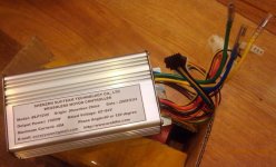
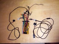
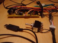
Mods have been slow, but here I've added some wires to the controller:
- Connector for the programming cable (oops, it doesn't fit in the controller this way. Luckily, I only soldered one pin, so it was easy to remove, turn and re-fit the pins on the JST-XH connector mate.
- Regen On/Off switch line, using two connectors of a spare CA pigtail, no switch on other end yet, just jumped.
- The two looped wires are not yet used.
- On/Off/Kill switch to go to handle bars.
2010-01-21 00.12.25_Washington_District of Columbia_US.jpg

The switch here is a joke... I've just added it for today, but have a momentary switch to use instead, in the middle of the black wire. Don't attach yours this way! I put it this way only to match the red wire with the 5V+ line, and assumed the rest would be correct... But the JST header won't fit in the case this way!! I had to turn it around...
2010-01-21 00.12.50_Washington_District of Columbia_US.jpg

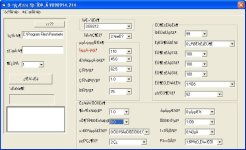
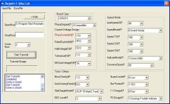
And I thought before programming it, I'd get the settings that Keywin used. Fresh out of my email, here they are in the latest version of the program (in Chinese only so far) that he also sent me. Doesn't it look the same as the 116 version?
751500_chinese.jpg
 
programming not working. nothing happening when i hit the switch...

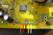
let's review: there's 6 holes on the board. i lined them up with the RED wire in the 5V+ hole (it's labeled on the back). The orange is hot, since it's connected outside the case, so is it supposed to line up w/ 5V+ via?
usb_jst.jpg
 
Greg,

Was the other controller the original from the Golden Motor kit? I have one from my first build and am considering opening it up and modding it for high voltage and current. How do you identify a particular12 fet controller? Can you point me to a relevant thread? For regen is the processor software particularly important making changing controllers a great idea?

Dave
 
dbaker said:
Was the other controller the original from the Golden Motor kit?
My controller history, in brief:
- 10/08: Got GM kit including stock 48V30A controller
- 6/09: Got 18.5V lipo booster & 75V30A controller from Steveo (who told me not to use it should not exceed those limits)
- 9/09: Got 75V40A MCU846 ecrazyman controller from nicobie for use w/ new 84V lipo pack... (afraid I'd blow steveo's) (switched to 9C about then too)
- 1/10: Got 75V45A MCU116 controller from ecrazyman (eBay) for HIGHER regen. Found regen w/ 846 insufficient.
- 2/10?: Getting 4110 fets from methods any day... :twisted:

I have one from my first build and am considering opening it up and modding it for high voltage and current. How do you identify a particular12 fet controller? Can you point me to a relevant thread? For regen is the processor software particularly important making changing controllers a great idea?

The threads are getting buried. Not sure which I'd recommend, although here's what I'd suggest to get a feel for the infineons:
Infineon Controller Technical (11/08) Note the add'l links at the end.

And here's what I think is the latest, the inspiration, a la Methods, ONLY 63 pages now...:
Instant Start 18 fet Infineon Boards are here..., started 4/09 and still cooking

Bottom line, if you're looking for a high amperage controller, and for you, since you've been used to 48V (right?), you have two options:

1. spend min 100 hours reading the threads, buying the parts, asking for support and building your own (like i'm doing, even though I fully intended to:
2. PM methods and ask him to build the stealth 6 fet with bells and whistles for several hundred bucks! :lol:

It's up to you!

PS: Sounds like building a 6 fet is excruciating, because of size... Love to have one though, w/ regen, reverse, speeds, cruise, etc...
 
Make sure the controller is powered down
Remove the programming cable (or lift the ground like you did)
Plug in the USB cable to the computer
Start the software and hit transmit
plug in the cable or close the ground
Should dump the code in a second or two


Orange wire goes to program enable. I just solder that pad to the +5V pad on the board.

116 cables come "lined up" out of the box
You may try removing the cable instead of lifting the ground as it is possible the USB chip is finding ground through the RX/TX pins and powering the chip.

Obviously you also have to use the 116 software :mrgreen: and not the 846.

-methods
 
It worked, but only after I:

- removed header from board
- turned on ghetto switch on GND
- plugged in USB
- clicked transmit
- poked board

in testing, before removing header, I noticed:

- when GND switch off, i measured ~1V across RED/BLK & across ORA/BLK
- when GND switch on, i measured 5V across (RED & ORA)/BLK

so perhaps it was getting some power. i'm only on p 22 of Instant Start 18 fet Infineon Boards are here..., so maybe I'll find the answer, but for now I can program w/ controller open...

thanks!
 
Going to test the controller on the bike soon. (Tedious that I have to change the Hall settings each time...) :roll:

Here are my new settings. Only difference really is lowered HaltVoltage to accomodate R12 mod.
751500_gc.jpg

I'm hoping to have some strong regen. We'll see!
 
GCinDC said:
Going to test the controller on the bike soon. (Tedious that I have to change the Hall settings each time...) :roll:

Wha?
What settings do you have to change each time?

-methods
 
Hey Methy

If you drop the phase current or rated current values in the software, does that actually work? Full Throttle has the programming working now.

As you know, I'd like to drop my current to 30A (45A controller), and that would be the easiest way.


If so, which one, phase or rated?


(And yes, I was also going to play with the throttle range switches).
 
Back
Top