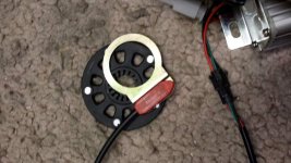
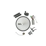
help troubleshooting first ebike build

Well D8veh suggestion to try connecting tnose wires only really holds true if he has experiece with that exact controller and wiring scheme. Otherwise you are just 'shooting in the dark


I don't understand your last paragraph about linking the battery black to PAS with the meter. You don't link anything 'through ' the meter unless you are measuring current. If you don't understand the basics of using a voltmeter to measure voltage, we are getting into dangerous ground, but I'll try and explain.
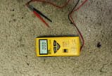
Picture of your meter will help us guide you

start with your meter in Volts mode at a high enough setting for your battery pack

Black and red meter leads plugged into corrrct sockets on meter.
Battery disconnected

Now put
black meter lead to black battery lead
Red meter lead to red battery lead

Flick the switch on your battery pack to work out which position is 'ON'. That will be the highest reading the meter gives. It may not go down to zero again immediately it is switched off. If it does nto seem to change, then leave the meter connected, and leave the switch in one position. and leave if for a few minutes, monitoring the voltage ont he display. If it goes down you have foudn the off position. If not, try the other position.

To learn a bit more about your meter, leave battery switch for now in 'ON' position and swap the meter leads on the battery. so red to black and black to ref. look at the meter display, note that it will now have a negative symbol in front of the voltage. That indicates tjat the vltage at the red lead is lower than the black lead.... The polarity is wrong, which in this case is obvious as the leads on the battety are colour coded. So now you can measure voltage and check polarity.


Now switch battery off and connect to controller

Switch battery ON
Nothing else connected to controller
Connect black meter lead to black battery connection, you will probably have to shove the probe tip the back of the black anderson, connection... you are 'T'ing ' off the battety controller connection

Now using the red lead from the meter go around all the other wires and see what voltage is on each one. If the controller is off, as it shoudl be with only battery connected, you should find one of maybe two wires at full battery volotage and that shoudl be it

Does the throttle have a switch and 'Fuel gauge'
? I believe I have already asked this once before?
If you know which is throttle plug from the controller and it does have on/off switch , then chances are it also had full battery voltage on one of the wires on the controller side of that throttle plug

Maybe now connect throttle to controller and with switch in both positions, check all other wires again. You should now see 5volts on some of the small red wires. When you do, then controller is 'on'


BUT. ....... I believe previously you had connected some of those loose single wires to the big red wire ? If you have done that, it may already be too late, you may have already fried the 5 volt regulator stage by feedimg 50 volts up it the wrong way

Apologies for poor spelling. Half closed eyes, fat fingers and iphone keybboard at 2 in the morning from bed here..edit..mostly corrected now
 
One post , one question, to make it easy to read

Your controller and motor came as a kit with all other devices, SO....


Do all the devices ( PAS, brakes, throttle, motor). only have one matching plug on the controller or is there mire than one way it can all go together?
 
In the 'ONE post One Question / request series

Pleaee post a picture of the throttle plug
 
In the 'ONE post One Question / request series

Pleaee post a picture of the PAS plug
 
In the 'ONE post One Question / request series

Pleaee post a picture of the plugs from the motor
 
OP's controller is the KU 151. It's wiring is more or less the same as the KU 123. KU93 and KU63, which I know very well except that they keep making small (normally insignificant) changes to the wires. If you look at those listings, there may be a download tab at the bottom of the page where you can download the connector schematic, though they're all slightly different. The wiring diagram they sent you must be for the old version, which used to have a separate ignition wire and no LED panel connector. They changed all those controllers about 9 months ago to have the option of the LED panel.

The controller is powered by the blue wire in that four pin connector. I already gave a description of what those four wires do.

The blue wire provides power to the 12v regulator that then provides power to the 5v regulator, which provides the 5v power for the CPU and all the sensors. The main battery wires go more or less directly to the MOSFETS, which block it until the CPU opens them. Nearly all controllers work like that except that they have different ways of getting the battery to the 12v regulator (ignition wires).

When a controller seems to be dead, the first thing you have to do is check that it's switched on. The easiest way to do that is to check whether the 5v is live. You set your voltmeter to 200v, put the black probe on any of the black battery wire connections and the red probe on the throttle or PAS connector red wire. 5v means that the controller has power. Alternatively, you can take the end-plate off the controller (opposite end to the wires), to see the red LED inside blinking. The blinking should be even intervals of on and off. If there's any pattern to the blinking, it has detected a fault; however,you can still have faults without it detecting them.

All tests should be done with only the battery connected. Then, connect the motor and check the 5v again, then connect the throttle and 5v again. Now test that the motor without adding anything else.

The controller automatically detects the phase and hall sequence. In most cases it gets it right, but not always, in which case you get humming or juddering from the motor. If it does that, you have to move the motor backwards to get it started and/or reboot the controller by powering off/on.
 
d8veh said:
K is for the LED panel. Blue is the ignition wire. The red is permanently live with battery voltage, so connects to blue to power the controller. Use a switch between them to switch the controller on/off. You can jump them for testing. The green is the signal for PAS level, which will default to level 1 without the panel. Black is ground for the panel.


I was just worried that he might have tried to connect the single blue wire "B" to the battery voltage, and not stripped the blue wire out of connector K.

Still worried about the throttle plug though.

Since the throttle has a switch and what appears to be a 3 light battery fuel gauge, the throttle wire could well be a multi wire plug with greater than the standard 3 wires or maybe the throttle wire splits to multiple plugs.


Not tried one of these controllers so I am only trying to help on a ' see what we have got basis' If you have used these controllers before Dv8eh then you are definitely the man to give better advice than mine. If I had realised earlier you know these, I would not have chipped in
 
The throttles with the switch and LEDs have three extra wires. I can't see them in the photo, but in case OP has that type, the wires are green brown and yellow. The green is for the LEDs, which share the throttle ground. The brown and yellow wires are the switch, so after testing, connect one to the red and the other to the blue, then you can switch the controller on and off without having to disconnect or switch off the battery. You should join the green throttle wire to the blue wire as well, then the LEDs will go on and off with the controller, so you know when it's switched on.When the controller is switched off, the drain on the battery is in the order of microamps, so you can leave it like that for a very long time, like months, but if you were to leave it that long, it might be better to disconnect the battery.
 
20150128_183709.jpgGentlemen,

Thanks for your continued assistance. Didn't know about the quote function, and now just can't figure it out. And I thought I was an internet guy. Anyway, have just gone through Neil's request for answers and will post that shortly. Then I will review your new posts starting with 7:02. Right now, please see attached pic of multimeter, as proper usage is such an issue at this point.
 
Here are answers to all previously asked questions.


When you initially connect the battery to the controller, do you get a big spark? or do you know about pre charge and have you done something to avoid it?

ANSWER: No big spark, and I’ve done nothing to avoid precharge.

I'd take everything off the controller...connect nothing.
Then Just connect the battery. red first then the black.
Then the ignition wire to the red main.
Now with a voltmeter, set at a range higher than your pack voltage, connect the black lead tot eh battery negative.

Now go around and probe all the other wires with the voltmeter red lead.
ANSWER: unclear--can’t find ignition wire and am unsure in terms of how to probe: Is black battery wire connected to controller first, and if so, can i probe into the pigtail connector with black lead?

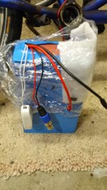
Are you saying the battery has three thick wires ..an orange a black and a red? Odd, but your picture only shows thick red and black

ANSWER: Battery has only red and black thick leads.

encinitas wrote:It also has a a small switch that, when toggled, the voltage jumps to 54.5V. And it has a connector for the charger. .

Where on the controller or the battery?

ANSWER: this is on the battery. vendor says it is only for shipping and should be switched on.


encinitas wrote:I assume that fat orange wire is what you are calling ignition?
Unlikely, the ignition wire will be a thin wire, almost certainly the same colour as the main battery input wire going to the controller....Unless all the wiring n this kit is some proprietary 'own brand wiring' then all deals are off as to what they have done. BUT Igntition wire WONT be a fat wire and it will come from the Controller..NOT THE BATTERY.

ANSWER: Understood. Small wire in controller.
encinitas wrote:Now when I connect the big red and black wires and measure V, I get 2-3. I figured, when the throttle is applied, voltage should jump, but it doesn't. Again, I have little electronics knowledge, so that is only an assumption..
Measure "V" ...but where are you measuring?

Get us a better close up pic of the wires and their plugs...with nothing attached. max res you can post on here is 800 pixels, if you want it to appear in the post. otherwise it will just appear as a link.
Splay the wires out as "fantail' flat on the table so we can really see what is what. If you want to be fancy , annotator th epicure in Paint/Photoshop etc with numbers so we can refer to exactly the same plugs.

50 volt is worrying.
Are you sure you are reading meter correctly , you shod maybe get battery voltage on one or possibly two wires.

A lot of the small red wires, on PAS, throttle etc should all have 5 vts or near 5 , maybe any where from 4-5 volts.

Of those wires with 5 volts on them, they should drop to zero when ignition wire is disconnected from main red.

ANSWER: I think I’m doing something wrong in the measuring. I have connected red battery lead to controller and used black probe on battery black, and red probe in the controller wires. During this, black controller lead is not connected.


Another question to ask you ...
Did the controller come with the rest of the matching parts? like throttle, motor, LED display, PAS, Cruise Brake levers etc?

ANSWER: Yes, kit came with motor, controller, throttle, PAS, brake levers. No LED display. Kit is BMS Battery Q11 48V 1KW motor.

If it did, and they all have matching connectors that can only connect to one other device and that device only , then wiring of most of them is not the issue.
ANSWER: yes, connectors from the parts in the kit are all unique. the remainder are the mystery.

Just finding the correct ignition wire is the issue and that will be one of the 'free wires.

..there are too many unknown wires here really. lots of singles.

The fact that you do not have a single red wires is 'odd'

I'd have suspected ignition to be red, it usually is


But you only have two single wires ? with no matching connectors and a couple of odd pairs.

ANSWER: There are 5 single wires. 2 White (G), 2 blue (G--I mislabeled, there are two, each with its own connector), 1 blue (B). The green and white pairs can connect (male/female) and indeed, green and white could interconnect. According to vendor diagram, these are speed limiter (white) and cruise (blue).

So :
pair of whites G
a pair of blue H
a blue B
a green. G
If either of the singles (B or G ) are not the ignition wires, and you have at one time connected them to battery voltage, then it may be too late. Firing 50 volt battery voltage on to a 'signal ' or '5 volt out' wire will not have done the controller any good, if it was not an ignition wire you may well have fried something .

ANSWER: this is totally possible.

Having briefly looked at some of the answer, i'd say some are wrong.
I say I think they are wrong, because you appear to have a block of 5 wires there, C in your picture is red, black, blue, yellow, green. That is a hall sensor block, almost 100% certain, and it connects to the motor right? If so then the pair of white CANNOT be a learning pair A "learning" plug is only for sensorless motors.

ANSWER: yes, this is a motor connector and vendor diagram indicates hall sensor

But, nothing is simple, I could be wrong....and that would be because the controller is Sensor OR sensor less type controller.
That blue pair 'could de to shoos sensor or not...don't know total guess. Depends on the plug(s) on the end of the blues. Can they be connected to each other?
Most of the white pairs I have seen are regen enable/disable. (Xie Chang controllers) ...Xlyte controller was also a pair of whites for sensor less, but rather than a single wire connector on each wire, it was a 2 pin connector, with a jumper plug that goes in to it.
.
ANSWER: see above re pairs.

You also mentioned a 'switch'. Is that the black box with the rocker in the photo? That could explain why you don't get the connection spark, because you are connecting the controller to the battery with the battery pack powered off.
Voltage across the Red and Black wires should go up when you flick the switch. It may not be zero as the BMS may hold voltage in capacitor even when off, and it may take some time to drain to zero. Does the voltage on between the red and black battery wires jump up when you flick the switch?

ANSWER: I think you are referring to first photo of the battery. The switch is a big white switch that is connected in both ends on the battery. Vendor says it is for shipping only and should be on. Voltage when off (measured across battery leads) is 50.4, jumping to 54.5 when switched on. It is next to charger connector, which may look like a black box.


encinitas wrote:
A -- Red and Black wires, battery connection

Correct


encinitas wrote:B -- Single Blue wire

Don't know. Any matching plug?

ANSWER: No matching plug. Diagram indicates high voltage brake.

encinitas wrote:C -- Five wires, black, yellow, green, blue, red? (maybe orange, I'm a bit colorblind)

Hall sensor to motor.


encinitas wrote:D -- Three wires, Black, yellow, red--pigtailled out to black, yellow only

I strongly suspect brake. It is wired to accept both a hall sensor brake (hence the red) and a normal swithc style brake lever.
That red should have near 5 volts on it. Connect voltmeter between black and red. If it is not 5 volts when controller is powered on then you have a problem. It should not be 50 volts

ANSWER: Yes. Brake on the two wire pigtail.

encinitas wrote:E -- Three wires, black, green, red

Throttle or PAS.

ANSWER: Throttle


encinitas wrote:F-- Three thick wires, bullet connectors, green, yellow, blue.

Phase wires


encinitas wrote:G-- Three wires, each with own connector, green, white, white

Do the whites have matching male / female plugs..so they connect to each other? Whites either learning or brake regen enable / disable...assuming this controller is following any sort of 'standard'

ANSWER: Matching plugs. speed limiter

encinitas wrote:H -- Two wires, blue, blue

No idea. do they have matching male / female plugs..so they connect to each other?

ANSWER: Matching plugs, cruise

encinitas wrote:I -- Three wires, green, blue, black

Again no idea. You'd need to check the outputs to see if any have 5 volt out. and which is ground. maybe this is PAS and E is throttle

ANSWER: three speed switch

encinitas wrote:J -- Three wires, black, red, green

Again , same as I or E Could be throttle, or PAS

ANSWER: PAS

encinitas wrote:K -- red, blue, black, green
Could well be this mysterious LED display, or a throttle plug for throttle that has a 'battery gauge'
Your throttle seems to have a switch, could be ignition.

ANSWER: Vendor diagram does not show this connector.D8veh has said this is LED display. I think he has the same kit. D8veh further said that red/blue in this connector would be ignition connection.

Is that possible a battery gauge the three white ovals on the front of the throttle?
Would need to see the wire connected to the throttle cable

ANSWER: Not sure what you are referring to about ovals.
 
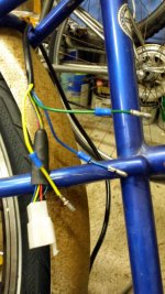
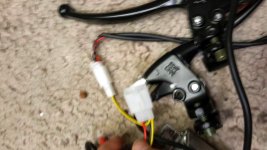
Please see photos of plugs below. I threw in one of the battery for good measure.

The throttle does not have a switch or fuel gauge--nothing other than a twister. As finally answered in previous post, the connectors to the kit are unique--there is no mixing them up.

So, I think I understand using the meter. I attached the battery to the controller, checked to see that the battery switch was on, and then I stuck the black lead inside the Anderson connector (black), and then put the red lead into the red wires coming out of the controller on the PAS plug and throttle plug. I also tried it on the red plug at K--the four wire LED connection that I took the red and blue wires out of and soldered to a switch. I tried with the red/blue switch in both on and off positions.

I got no V whatsoever at any of these points. I rechecked several times, and also measured V across the battery to check that I had the black lead solidly connected. I did get voltage between the two battery leads: 54V.

I also removed the endcaps on the controller and looked for light. I didn't see a lightbulb. Nor was any shining.

Perhaps I've fried the controller with the meter connecting it to battery?

One other possible thing: I read in another post of problems with this battery. I'll dig up the post and paste it in, and you can tell me if this is an issue.


20150128_190207.jpg20150128_190145.jpg20150128_190117.jpg20150128_190027.jpg
 
Here is the issue I mentioned: another user was having problems turning on controller with the same battery I bought.

http://endless-sphere.com/forums/viewtopic.php?f=2&t=64977&p=991093&hilit=calibike+48v+15ah#p991093

Perhaps one solution would be to take my controller to ebike shop and ask them to test. I hate to have to fall back on a local shop when I've gone out of my way to do a DIY.
 
I am at work so just a few answers here , I'll go through tht other post later.
encinitas said:
The throttle does not have a switch or fuel gauge--nothing other than a twister. As finally answered in previous post, the connectors to the kit are unique--there is no mixing them up.

OK, so it is a different throttle to the one you pictured in your first post

This is the picture, from the link you gave, showing throttle with red button switch and three 'ovals' picture from your first link

Someone else also mentioned the red button and it needign to be out to run...but if you dont have that throttle...no nmeed to worry.

q11-48v1kw-rear-driving-e-bike-conversion-kit-ebike-kit.jpg


encinitas said:
So, I think I understand using the meter. I attached the battery to the controller, checked to see that the battery switch was on, and then I stuck the black lead inside the Anderson connector (black), and then put the red lead into the red wires coming out of the controller on the PAS plug and throttle plug. I also tried it on the red plug at K--the four wire LED connection that I took the red and blue wires out of and soldered to a switch. I tried with the red/blue switch in both on and off positions.

I got no V whatsoever at any of these points. I rechecked several times, and also measured V across the battery to check that I had the black lead solidly connected. I did get voltage between the two battery leads: 54V.

This is worrying. IF the ignition is ON, then some of those leads shoudl have voltage on. Since you dont appear to have the throttle in the picture, then we must assume that the blue from K is the ignition wire. so with that ON and battery ON there shoudl be voltage on some of those wires.


encinitas said:
I also removed the endcaps on the controller and looked for light. I didn't see a lightbulb. Nor was any shining.

This I dont know, must be specific to the KU controllers Dv8eh will have to answer that. None of the Xie Chang standard controllers i have seen have an LED. Some Crystalyte one had a switch and an LED ont he case. but never seen one with a LED ont eh board hiddn in the case for diagnostics.

encinitas said:
Perhaps I've fried the controller with the meter connecting it to battery?


No, no chance of that if you have only ever had the meter set in voltage mode and the leads in the correct holes for voltage , and the red lead has not been in the Amps hole on the meter.
The meter will not pass voltage or current to any other component through itself in voltage range. The only possibility of damage woudl have been if you had the leads misconnected on the meter and used Amp measuring range, and then connected one end of meter to the positive and one end to a groudn or data connection. .That woudl also have had to happen while the battery was powered on.

Did you ever connect any of the other single wires direct to the thick red battery connection ? to test for ignition wire?
 
It's very simple to test your controller and your battery, but you don't seem to be taking a logical approach. I told you about what the wires do in a very early post.

1. Start with the battery. Put your voltmeter on 200v scale and measure between the red and black power wires.
2. Connect only the controller to the battery with nothing else connected to the controller. Measure the voltage between the red and black wires on the 4-way connector that also has green and blue.
3.Put a bit of wire between the red and blue wires on the 4 pin connector to turn the controller on. There's black wires on the PAS, throttle, three-speed switch and the 4-way connecor with the blue wire. All those blacks are common grounds, so when you think that the controller is switched on, put your black probe on any of the pins with those black wires and your red probe on either the PAS or throttle red. 5v there will tell you if the controller is actually switched on

Please let us know those three results, then we can take you further. We don't need to know anything else.
 
encinitas said:
am unsure in terms of how to probe: Is black battery wire connected to controller first, and if so, can i probe into the pigtail connector with black lead?

Probe is not meaning any particular way of connecting..it just means 'touch with the multimeter probe...to make contack to get a reading..no need for a mechanical soldered or twisted connection...it is jsut sticking th eprobe from the meter on to another wire or connector to see what its voltage is.
You would usually have the black lead (probe/ wire call it what you want) from the meter connected to the main ground / negative wire of the battery and controller...
Then you 'probe' (poke ) around with the red probe lead of the meter on to other terminals.
Double check the meter is in voltage mode first, and the leads on the meter end are in the correct holes. Black usualy to a Com (common) socket and the Red to a V socket NOT to a socket marked somethelign like A, or amps or 10A.

As we have now both said.. Start simple...Controller and battery ...nothign else.

That red wire on the K plug, that you tell us you have connected a switch to. That should have battery voltage on it. so 54 volts
 
I think I've caught up to you now and understand how to use the probes correctly. I left it alone for a few hours and am now testing per your instructions.

voltage reading on the battery by itself: 54.1

I then connected the battery to the controller, nothing else connected. black probe touching the black battery lead at the anderson connector.

voltage at red wire on 4 way connector per D8veh: 54.1V

I then flipped the switch connecting the red and blue wire on the switch and measured voltage at the red wire on the PAS connector and then again on the throttle connector: 5.03V on both. With the switch off, they are at 0.00V.

Now I'm going back to bed. Ready for further instructions.
 
To answer Neil's question, I never connected the battery to anything other than the battery connections on the controller.

And yes, different throttle. I'd forgotten to look closely at that first picture and had been wondering why we were talking about a red button. Glad that is cleared up.

Finally, multimeter does not have different connections for the probes. It is digital, and I've only used the V setting. It would seem I can discard the fear that I fried something, at least so far.

Thanks again for keeping with me on this.
 
Right, so everything is probably OK with the controller. Let's try starting with the throttle. Connect the motor phase wires (thick blue, green and yellow). Make sure that the colours match. Then connect the hall wires. Have a look at the hall connector and make sure that the colours match from one side to the other.

With everything switched on, check the voltage between the black and red on the hall connector, which should be 5v.

Now connect the throttle and check that it also has 5v between the black and the red wires. If that's OK, move your probe from the red to the other wire whatever colour it is (green or white?). It should be just over 1v. Now be careful in case the motor fires up when you do this. Operate the throttle and you should see that go up to nearly 4v. Have a listen to the motor. Is there any hum when you open the throttle. Give it a kick forward to see if it starts.

If all the voltages are OK, but still the motor doesn't go, make a cup of tea/coffee and let us know, so that we can go to the next stage.
 
O joy!

I hooked up the throttle, got 4.38 volts when I applied throttle. Hooked up the hall connector and phase wires, got voltage, lifted up the wheel, gave the throttle a twist and, yes!, power delivered to the wheel! The sound is a low whine, seems normal to me.

One thing that I discovered when I opened the controller was that a wire had been caught and crushed between the case and the end plate, with the insulation breached. Whether this was a cause of nonoperation, who knows?

In any case, many thanks for the instruction and patience helping me. I learned a lot.

Now that the motor runs, I do have some other questions, of course ...

Is there generally anything else I need to be aware of?

Is there a simple and inexpensive display that works well with this system? Just a battery indicator would be enough given my planned usage. Related, if I don't go the display route, what suggestions for rigging a more permanent on/off switch. I think D8veh said leaving the ignition permanently connected is not a big drain, but for safety's sake, I'd want to disable the throttle when not in use.

Thanks again for all the help. Now I can finish setting it up. I'll post a picture when finished.
 
Unplug the battery from the controller when not in use or it will drain your battery. This will work well hooked to the controller side of the battery connections.
http://www.ebay.com/itm/DC-15-to-120V-Waterproof-Red-LED-Panel-Meter-DC-Digital-Voltmeter-Two-wire-NIGH/141365876290
 
When you disconnect the blue from the red wire, the drain from the battery is totally insignificant. Everything including the throttle will be switched off.

Those controllers have an automatic motor detection sequence at start up. They don't always get it right first time. Sometimes they need a bit of help by spinning the wheel by hand. Once they've got it, they don't forget. Sorry to have to take you through all the checks, but I needed to know that everything was connected properly and the controller switched on. You don't need the LED panel as long as you can find a suitable way of installing the switch. The panel gives three PAS levels, but I guess you don't use PAS with a motor like that.

The LED battery indicators are nothing more than rudimentary voltmetwers. You can buy a digital voltmeter from Ebay for a few dollars, which will give much more info. Search for "waterproof digital voltmeter", then find one with a high enough voltage.
 
The exact answer is not clear. Normally, you see the motor jump or hum if the controller doesn't get the correct start up sequence. If it does that, you can try again by switching off/on, and if that doesn't work, you give the motor a kick (backwards if it's geared).

In the above case, there was also a damaged wire, or it could have been some connection fault.
 
Thanks for clearing that up d8veh. That's is the case with multiple electronic connections. Plus we are getting this as cheap as dirt.
Plus what helped alot was encnitas answering all the questions posted. That's a nice thing a letting us know he got it running and not just disappearing on a ride.
On the cali battery the white is the off/on switch ? And would like a review over time on the cali battery.
 
Back
Top