**Important** reality check on motor, voltage, current etc.

Jeremy Harris said:
This relationship between throttle setting and current ratio is important. I'm sure people here have read of non-current limited RC controllers popping at low speed, part throttle. If you try and baby one of these off the line, with just a tiny throttle setting, then what you're really doing is forcing the controller to deliver very high peak current pulses to the motor. AFAIK, these things don't have any form of current limiting, so if, for example, you had a 50V system, decided to only open the throttle 10% at start up and had a start up power requirement of 800 watts to get the bike accelerating, then although the battery current would be a nice, safe, 16 amps (at 800 watts) the motor current would be ten times this, 160 amps.

This would be true if the startup requirement was 800 watts but there is no "start up" requirement. Sure, if people felt that 800 watts was necessary to achieve the acceleration they desired, then that would be problematic...

In that situation, if the controller delivered 160 motor amps at 10% of the input voltage, it'd be obliged to send 100% of that at full throttle (Because the motor voltage would be 10x at much), or 1600 motor amps. :shock: Please let me know what controller and motor you're running, because I don't think any controller we currently have would survive that, and not many batteries and motors supply that at start-up.

I think what's more likely to happen in real life is that people will "baby" the throttle with 50% or some such, and instead of producing a full throttle phase current of 320 amps (For example), it produces a lower 160 phase amps. That's still a lot, and switching losses will likely exceed the heat design of the controller. AFAIK, turning a prop doesn't involve 160 motor amp periods for long periods of time (i.e., more than a second) which is why phase current limiting isn't necessarily used (Though, yes, castle does use phase current limiting as startup until sync is accomplished.), and requiring 160+ motor amps for more than a few seconds will likely kill it (As is the case with someone accelerating).

The above discussion applies to speed-based throttle control. Not all throttle control is speed based.

If your battery current is low enough, though, your input power will be sufficiently low that max current that can be supplied to the motor will be below that "danger zone". I'd use something like my simulator to predict the phase current and see if it exceeds the controller's limitations. Also, higher gearing is excellent because it reduces the period of time that there's high current load on the motor. I think this is why friction-drives with 20:1 and up gearing ratios have done a lot better than bikes with a gearing ratio half that or less.
 
swbluto,

Jeremy didn't say anything about startup or acceleration, his was the basic example at cruising speed and partial throttle. The part you're missing is that under heavy load the 50% babying of the throttle is quite likely to result in much higher phase current than the 320a of full throttle, not half the current. That is one of the main points of the thread.
 
John in CR said:
The part you're missing is that under heavy load the 50% babying of the throttle is quite likely to result in much higher phase current than the 320a of full throttle, not half the current. That is one of the main points of the thread.

That's EXACTLY the part that you're missing. Just go to http://ebikes.ca/simulator, choose whatever combination you want and notice the motor torque at the beginning. Now reduce the throttle to, say, 50%. Tell me how that affects the starting motor torque. And, if it doesn't become clear then, then know that motor torque is just an expression of phase current. That is, torque = some_constant*phase_current.


In one of the most recent tries I did, reducing the throttle to 50% reduced the phase current to 75% of its original full throttle phase current. However, that's with current limiting. Let's eliminate current limiting and let's try again (Put the current limit to some really high number, like a 1000).

Without current limiting, bringing the throttle down to 50% brought the starting phase currents down by about 65%.
 
swbluto said:
John in CR said:
The part you're missing is that under heavy load the 50% babying of the throttle is quite likely to result in much higher phase current than the 320a of full throttle, not half the current. That is one of the main points of the thread.

That's EXACTLY the part that you're missing. Just go to http://ebikes.ca/simulator, choose whatever combination you want and notice the motor torque at the beginning. Now reduce the throttle to, say, 50%. Tell me how that affects the starting motor torque. And, if it doesn't become clear then, then know that motor torque is just an expression of phase current. That is, torque = some_constant*phase_current.


In one of the most recent tries I did, reducing the throttle to 50% reduced the phase current to 75% of its original full throttle phase current. However, that's with current limiting. Let's eliminate current limiting and let's try again (Put the current limit to some really high number, like a 1000).

Without current limiting, bringing the throttle down to 50% brought the starting phase currents down by about 65%.

The shortcomings of a simulator do nothing to support your case.
 
donob08 said:
Jeremy

I understand that you gave us the requirements for each speed as far as the motor is concerned, but who gave them to the battery? We only told it we want average current to be half of what it was. It doesn't know about 100 Watts / 50 Volts = 2 Amps. It only knows 50% duty cycle means 8 Amps.

If we say the battery is putting out 400 Watts: 8 Amps at 50 Volts and the motor is only needing 100 Watts to do half speed we are going to be going a lot faster than half speed.

Am I missing something? Is the motor current going to be 1/2 of battery current and motor voltage 1/2 of battery voltage to get the 400 Watts down to 100. How is the Current Division done?

Don


The battery will only give what the motor asks for, so at half speed there would no longer be the 400 watt load- it would be 100 watts. The battery can't push out more power than the motor asks for (ignoring other sinks in the system). At 50% throttle, assuming a voltage based control, we have 50% duty cycle which halves the motor speed as compared to full throttle. 1/2 speed = 1/4 the load roughly, Jeremy's example is spot on.

Getting into the current limiting zone is a HUGE can of worms. While a motor is running in current limiting, the starting torque doesn't change until the PWM is low enough to stop current limiting. Even at 50% throttle many combinations don't lose starting torque on the ebike.ca simulator unless a very high turn count is chosen. For example, a 404 on 20a starts losing starting torque around 52% throttle, whearas the 408 starts losing torque around 62% throttle. Watch for the first knee to converge with the X axis. When it does converge, it is an indication that either battery or phase limiting has changed.

One item that I must address is the torque of a given motor/ voltage/ geardown. While a different wind does not allow the motor to produce more power or torque, a slower motor will allow more torque to be produced with an amp limited setup assuming that both winds hit amp limiting during acceleration. Basic motor theory, slower motors produce more torque per amp at a tradeoff of top speed and available power (assuming that no other changes are made).
 
I have to agree JohnRob, and as long a someone is running a good battery pack for high performance, then all of our controllers are limiting current in some way, negating this idea that the same motors with different windings have the same torque. They have the same potential torque, but that's only if the battery/controller combo are set up to deliver high enough current to the low turn count motors.

The viewpoint of different windings of the same motor being equal also leaves out the significant impact of the big advantage in efficiency of the higher turn count motors in the early stages of acceleration. Even if somehow power in is somehow equal at 5, 10 or 15 mph, power out is significantly higher for higher turn count motors at those low speeds during acceleration. Is that early stage efficiency difference linear with winding count?

My question remains as to what is limiting the current in the controllers. It's not just PWM chopping that limits the current. There must be some other mechanism regulating the current near the front end of the controller.
 
John in CR said:
My question remains as to what is limiting the current in the controllers. It's not just PWM chopping that limits the current.
IIRC, it is.
 
John in CR said:
My question remains as to what is limiting the current in the controllers. It's not just PWM chopping that limits the current. There must be some other mechanism regulating the current near the front end of the controller.

It is just cutting back the pulse width that's doing the current limiting. If you cut the width back far enough, the relatively slow rate-of-rise-of-current with time, caused by the motor and wiring inductance, will act as an effective current limit. There's no other way that the controller can limit current, short of shutting down (which some will do when faced with a high instantaneous current demand).

Jeremy
 
Jeremy Harris said:
John in CR said:
My question remains as to what is limiting the current in the controllers. It's not just PWM chopping that limits the current. There must be some other mechanism regulating the current near the front end of the controller.

It is just cutting back the pulse width that's doing the current limiting. If you cut the width back far enough, the relatively slow rate-of-rise-of-current with time, caused by the motor and wiring inductance, will act as an effective current limit. There's no other way that the controller can limit current, short of shutting down (which some will do when faced with a high instantaneous current demand).

Jeremy

This doesn't seem to jive with real world results using different controllers with the same low turn count motor. My stock controllers should have fried long ago with extreme PWM chopping that would be necessary. There has to be something else limiting current, or is it chopping it so fast that the delay due to inductance just never allows the phase current to rise fast enough to get out of control? Bottom line, if it's just PWM and current limiting is hard on the controller, then why does a lesser controller survive, while the super controller ran tremendously hotter and was toast on one of the first hill climbs with me aboard?
 
John, your question is very good. The answer is that the current multiplication has a limit that stops it from climbing at some point. I think this point is generally 3-4 times battery current, but may be as low as only e (2.78) times battery current. I just woke up, and this is fairly heavy stuff, but im going to keep working on finding the rationships that outline the current multiplication limits.

But essentialy, with a controler set for 25 battery amps, its going to only be peaking a max of something like 75-100phase amps in its worst case situation.

A controller set for 100battery amps can be seeing 300-400 phase amps in the worst case situation.

It finally seems clear why Keywin labels those 12fet controllers with 30-45amp max battery current rating, even though we look inside and see a pair of FETs able to handle +75amps each. He knew to keep the controller safe from extended operation in the worst case scenerio, that 45amp battery current would be maxing the 150amp FET capacity.
 
John in CR said:
Bottom line, if it's just PWM and current limiting is hard on the controller, then why does a lesser controller survive, while the super controller ran tremendously hotter and was toast on one of the first hill climbs with me aboard?

Assuming everything else is equal (Same motor, same hill, same speed, same voltage, etc.), the mosfet's gate capacitance might have an affect. "Super controllers" du jour use 4110 that have far higher gate capacitances than "lesser" mosfets. This has the affect of making the "switching part" of the mosfet longer, letting it endure the "switching heat loss" for longer periods of time. Also, if the controller has more mosfets and the drive circuitry hasn't changed, then it could be reducing the gate current per mosfet delaying the switching speed (And thus increasing the switching loss heat).

All just speculation.
 
liveforphysics said:
I think this point is generally 3-4 times battery current, but may be as low as only e (2.78) times battery current.

It must be something like this in practice. I read into your first posts a bit of "conservation of energy" and the idea that if duty-cycle goes down then current must go up proportionally .But this implies a sort of steady state condition.

Most of this stuff is still way over my head but I think it all has to do with inductance , and "inductance" is just a difficult thing to grasp or understand how it actually behaves in/over a certain time-period.
And it is still a combination of the inductance laws and the normal resistance/voltage/current laws which makes it two things happening at the same time and human beeings have difficulties with that ! ( I certainly have)

For instance : you can have a PWM pulse from the controller to the motor of a certain voltage but who is to say that the coil actually "takes" this voltage pulse and current flows ? Isn't it more something like a voltage "potential".....
The whole thing is probably not happening in a linear scale either.

I hope someone will figure it out , because knowing what would be the absolute max peak pulse current when you know some resistance/inductance numbers of the E-motor that you want to use will help in knowing how far you can push the mosfets.

edit: I just realised we have THREE things to consider in this .

1: the battery current
2: the average mosfet current (=heat ??) that is supposedly higher sometimes than battery current
3: the peak pulse current the mosfet sees when it wants to put power in the coil

could the last one also be the reason why controllers blow at low pwm duty cycles ? Too much peak current because of inductance.
 
Hmm.... Once I fix the CA and the Turnigy, I'll have three functioning watt meters. With a fourth I could then put one on each of the phases, plus one on the battery, and *watch* what happens under various conditions. Of course, only the CA will read the reverse-current, so I guess ideally I'd need four CAs (three at least).

Anybody got four CAs they're willing to wire up to their phases and battery, go out and do some tests? Ideally with logging enabled on each one, plus one of those memory-card dataloggers attached to each. ;)

Sample rate might not be fast enough to tell the whole story, but it could help to see it all in graphed form from the log results of that kind of test.
 
Fligh High said:
liveforphysics said:
I think this point is generally 3-4 times battery current, but may be as low as only e (2.78) times battery current.

I don't think there's an absolute "limit". If you find a simulator that lets you change the battery resistance and so on, I think you'll find you can make the "multiple" arbitrarily large. With real systems, though, where the battery + connection + controller resistance is something like 60-200 mOhms, that can easily be equal to or more than the motor's resistance putting an effective limit on the multiple. By the time the voltage reaches the "output of the controller", it can be significantly less, and PWM brings down the motor voltage that much further. (And, that average motor current is simply that motor voltage / motor resistance. At higher RPMs, where the electrical RPM is higher, than inductance can come into play further reducing the average phase current.)

Also, another significant aspect of that is the "diode drop" inside the controller.

Let's use an example. Say one is using a 50 volt battery pushing 40 amps. If the duty cycle is at 10%, you'd *gasp* say that the motor current must be 400 amps. But, what happens is that the output voltage is reduced by 10 times. That's 5 volts. But, wait, there's a diode drop in the controller... so now it's down to 4.1 volts. Now let's take a low motor resistance of .03 ohms. That's a stall current of 4.1/.03 = 136 amps... not quite the 400 amps you originally expected. In actuality, those numbers don't actually work together - they actually follow a fairly specific formula that's not been mentioned yet. I'd pull it up but... well, no one is interested, as far as I can tell, and it doesn't seem anyone would care to understand it anyways. But, if it whets anyone's appetite, it involves a quadratic. :)
 
amberwolf said:
Sample rate might not be fast enough to tell the whole story, but it could help to see it all in graphed form from the log results of that kind of test.

The max current reading will likely be accurate enough. But... I take it you're using the standalone Cycle Analyst. Where's the wires used to be power the cycle analyst? I was under the impression it was integrated into the mold shunt but I could be wrong. If it's within the molded shunt, then powering the CA from the shunt could be problematic.
 
Powering the CA could be done externally; shouldn't be an issue I think, since all the pads are still the same inside the CA even if they aren't hooked up in the standalone/shunt version.

But yes, IIUC it would require the standalone version with it's shunt inline with the phase under test to read it, and then each CA powered off a separate battery, so that isolation of grounds/etc. would not be an issue.
 
Isn't the whole phase current stuff not easy to see on a scope ? Use low resistance shunt or maybe even the phase wire itself and see what the current does with the different PWM rates...

It may give an easy answer to all this discussion :)
 
Don't forget you need a couple of hub motors, both a normal one and a lower turn count motor, and a programmable controller. If you're going to the trouble, you might as well dive all the way in to come up with useful data instead of just interesting data confirming that phase currents increase during current limiting.
 
John in CR said:
... why does a lesser controller survive, while the super controller ran tremendously hotter and was toast on one of the first hill climbs with me aboard?
81V * 60A = 4.8KW (30A w/halved shunt)
81V * 100A = 8.1KW

Multiply by inverse of duty cycle...

Big difference.
 
John in CR said:
Don't forget you need a couple of hub motors, both a normal one and a lower turn count motor, and a programmable controller. If you're going to the trouble, you might as well dive all the way in to come up with useful data instead of just interesting data confirming that phase currents increase during current limiting.
That's the idea; I have a fusin geared motor and a 9C 2807; should shortly have another I forgot what it is. GM of some type in a 9C shell. Lyen 6FET programmable, and if I ever get it fixed a Methods 18FET, plus the original Fusin. (and a few others that need fixing but are not programmable, most are analog).

But I dont' have the equipment to do the logging, which is where someone else with multiple CAs and research money to buy the loggers will have to step in; hopefully they also have multiple motors and controller that can be setup for various modes.
 
I think some may be getting confused by the analogies here. It's misleading to think of the battery "pushing" current. A better analogy is the motor "pulling" a particular phase current. That phase current (speaking in averages here, since the current goes up and down over a PWM period) multiplied by the duty cycle determines the battery current.

To use swbluto's example:
swbluto said:
Let's use an example. Say one is using a 50 volt battery pushing 40 amps. If the duty cycle is at 10%, you'd *gasp* say that the motor current must be 400 amps. But, what happens is that the output voltage is reduced by 10 times. That's 5 volts. But, wait, there's a diode drop in the controller... so now it's down to 4.1 volts. Now let's take a low motor resistance of .03 ohms. That's a stall current of 4.1/.03 = 136 amps... not quite the 400 amps you originally expected.

If the motor is drawing 136A at 10% duty cycle, then the battery current will be 13.6A. As his numbers above point out, it's not possible for the battery to "push" 40A because the motor isn't drawing 400A. Under most conditions it's unlikely that the motor will be pulling the full current allowed by the resistive limit, but phase current determines the battery current not the other way around.
 
I just did a quick derivation (which I think is correct...) that might help clear up some of the confusion:

Assumptions:
- The PWM frequency is fast enough that the current waveform can be considered a straight line (should be true)
- Neglecting "small" voltage drops - wires, FET on resistance, etc.

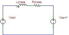
A controller is functionally identical to a DC-DC buck converter. We can ignore the three phases and use a simple model:
Simple Model.PNG

When the controller is on, the model is thus:
On Model.PNG

Using Kirchoff's Voltage Law, we can derive the equation: Vbatt-Vbemf-Iavg*Rphase=Lphase*dI/dt, where Iavg is considered to be the average current over the PWM period (simpler this way).

So, during the on-state the current slope is given by: dI/dt=(Vbatt-Vbemf-Iavg*Rphase)/Lphase

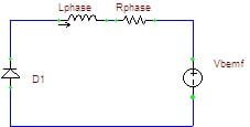
When the controller is off and the diode is freewheeling:
Off Model.PNG

Using the same technique we derive the KVL equation: -(Vbemf+Vdiode+Iavg*Rphase)=Lphase*dI/dt

During the off-state the current slope is given by: dI/dt=-(Vbemf+Vdiode+Iavg*Rphase)/Lphase

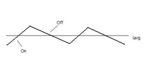
The waveform looks like this:
Current Waveform.PNG

Using the slopes found above, we can calculate the current ripple during on- or off-time by the duty cycle:
deltaI(on)=(Vbatt-Vbemf-Iavg*Rphase)/Lphase*D (where D is the duty cycle)
deltaI(off)=-(Vbemf+Vdiode+Iavg*Rphase)/Lphase*(1-D)

If the system is operating in steady-state at a constant average current, the magnitude of both deltaI terms must be equal:
(Vbatt-Vbemf-Iavg*Rphase)*D=(Vbemf+Vdiode+Iavg*Rphase)*(1-D)

Note that the inductance divides out. The actual PWM period is not important, so long as it's short enough that assumption #1 above applies, because the period would also divide out.

We do a little bit of algebra to get:
Iavg=(Vbatt*D-Vbemf-Vdiode*(1-D))/Rphase

Compared to the other terms, Vdiode is pretty small, so we can get rid of it and simplify to:
Iavg=(Vbatt*D-Vbemf)/Rphase

This equation agrees with a few things we know to be true:
- If the motor is at a dead stop (Vbemf=0) and the controller goes to WOT (D=1, no limiting), the current is Iavg=Vbatt/Rphase, the Ohmic limit
- If the throttle setting exactly equals the motor BEMF (Vbatt*D=Vbemf), no average current flows (in this simplified model)
- Similarly, at WOT (D=1), average current also drops to zero when BEMF reaches battery voltage (Vbatt=Vbemf)

I hope you're still with me, because now I'm going to point out how this helps the discussion!
- All other things being equal, decreasing the duty cycle decreases the average phase current flowing. This is why limiting works.
- All other things being equal, higher speeds -> higher BEMF -> lower phase current.
- If we assume limiting is in effect and phase current remains constant, higher speeds -> higher BEMF -> higher duty cycle D. This is why the throttle gradually gains more effective range as the bike speeds up when limiting is applied.
- Holding a constant throttle (D), if you go up a hill and speed starts to drop (Vbemf decreases), Iphase will increase assuming limiting is not in effect.
 
rhitee05 said:
I hope you're still with me, because now I'm going to point out how this helps the discussion!
- All other things being equal, decreasing the duty cycle decreases the average phase current flowing. This is why limiting works.
- All other things being equal, higher speeds -> higher BEMF -> lower phase current.
- If we assume limiting is in effect and phase current remains constant, higher speeds -> higher BEMF -> higher duty cycle D. This is why the throttle gradually gains more effective range as the bike speeds up when limiting is applied.
- Holding a constant throttle (D), if you go up a hill and speed starts to drop (Vbemf decreases), Iphase will increase assuming limiting is not in effect.

Right on.

I also fully support that it's a matter of the motor asking for a "certain current", not that the battery is operating at a specific battery current and arbitrary duty cycle. Bigger motors / lower-resistance motors naturally ask for more.
 
My big motors haven't met a controller that could deliver what they asked for, so sorry but my motors aren't drawing what they want. They're saying send me whatever you can.

What happens during current limiting is the juicy part of this thread, because what goes on in the normal course of typical operation outside of current limiting isn't stressful for a controller.

Riding a bike at high power that has current limiting all the way up through normal cruising speed is a totally different experience than riding a high power bike whose top speed is near normal cruising speed. If we can figure out how to keep the phase currents under control during current limiting so these cheap controllers don't stress themselves too far, while maximizing performance and durability, then we're on to something good.

John
 
No argument with the above (re buck-topology), but aren't we forced to consider the *peak* phase current during PWM... because that's when magic smoke comes out?

rhitee05 said:
Under most conditions it's unlikely that the motor will be pulling the full current allowed by the resistive limit...
Don't motors draw stallCurrent minus BEMF? So at startup, Full current is inevitable, mitigated only by PWM ?
 
Back
Top