
You are using an out of date browser. It may not display this or other websites correctly.
You should upgrade or use an alternative browser.
You should upgrade or use an alternative browser.
Inductance What is it what does it do? Collosus has 8uH!
- Thread starter Arlo1
- Start date
We need low resistance inductors. I Will most likly wind my inductors for collossus with 10awg and 2 strands parallel.Njay said:Lots of ferrite inductors on PSUs...
I was hoping to find one ~$100 or less but... It all depends on how much I need it. I live on Vancouver island so the chances of finding someone who can lend me one are slim and then every time I wind a motor needing it again would also be a PITA. I did scope collossus the first time I got it running and the video is on youtube and linked in the collossus thread. I will see what I can come up with. As for scoping collossus again I will not run it till I think I have enough inductance for my 24 fet to not freak out. I blew up two 24 for controller on it already and that's getting costly. Not to mention the time it takes to build one up!fechter said:They tend to be pretty spendy. Best to find someone who has one and borrow it.
I think the one I got at work was around $275US. BK Precision, but I forget the model. Cheap but seems to work pretty good.
On your inductors, I would suggest using some kind of core like a powdered iron torroid. To get the same inductance with an air core, it will need way more copper and have a lot of resistance losses. The motor iron will saturate before the torroid most likely, so I don't see much down side.
Another way to measure would be to look at the waveform on the phase wires during switching with an oscilloscope. You can see if the slope starts to flatten out toward the end of the cycle indicating not enough inductance.
"Low resistance" is actually very ambiguousArlo1 said:We need low resistance inductors. I Will most likly wind my inductors for collossus with 10awg and 2 strands parallel.Njay said:Lots of ferrite inductors on PSUs...
") . With PSUs having 5V outputs of 40A and maybe more, they can't have much resistance (here's another ambiguous expression). Anyways, if you want to wind your own inductors, PSUs can also be a good source of ferrite cores, given that lots of PC PSUs can be easily found for free. You can parallel inductors, getting lower resistance (and lower inductance). Just a hint.
. With PSUs having 5V outputs of 40A and maybe more, they can't have much resistance (here's another ambiguous expression). Anyways, if you want to wind your own inductors, PSUs can also be a good source of ferrite cores, given that lots of PC PSUs can be easily found for free. You can parallel inductors, getting lower resistance (and lower inductance). Just a hint.bigmoose
1 MW
If you are recycling power supply toroids, think of them rated in ampere-turns. So 10 turns with 1 amp will saturate the same as 1 turn at 10 amps... sort of. You can stack toroids to get more of the ferrite area into flux, and thus increase the power handling of the "stack" That is you stack them up and wind through them all.
rhitee05
10 kW
I think you'd be better off sticking with an air-core inductor. Ferrite would give you a lot higher inductance, but I think saturation would be an issue unless you use a really big core. You can get the inductance you need by either using many turns or just by making the diameter larger, and keep the loss low by using a multi-strand wiring or just a larger gauge.
Using a scope to find the inductance is a good tip. Even if you can run the motor at very low throttle, that would be enough. Once you've measured the phase resistance, you can use that to get an estimate of the total inductance needed to make the motor controllable. You still need the phase inductance to know how much to add to get that total, though.
Using a scope to find the inductance is a good tip. Even if you can run the motor at very low throttle, that would be enough. Once you've measured the phase resistance, you can use that to get an estimate of the total inductance needed to make the motor controllable. You still need the phase inductance to know how much to add to get that total, though.
I blew up to many controllers to use the oscilloscope test until I think I have close to the right inductance to start it.
My x5 has 20 times more resistance then collossus. I did the voltage drop test to mesure resistance and one phase of collossus is .009285 ohms and my X5 is .1840579 ohms I will do some calcultations and find a place to start today then do some more tests on collossus asap.
[youtube]5L6JcgRvJYE[/youtube]
So I scoped the PWM of my 24 fet on my bmx and the pulses are from 5-60 useconds from the best I can tell. I used all kinds of throttle settings and all three speed settings to get a reading on the dyno. So Big moose if a guy wanted to know the current build time based on the uh of a motor for say 96volts could he just double the numbers of amps you have listed in the chart. So say at 75 useconds a motor with 34.6 uh and resistance of 35.1 mohms would build to 200 amps?
Attachments
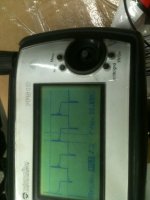
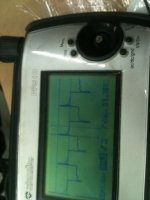
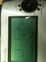
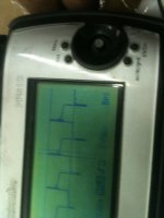
So I did a couple more scope readings of the inductors I made. Here is the pictures. I figure the inductance is to low because I measured the voltage drop across the inductor and found that the calculated 15uh inductors I made seem to work for around 20us if the pulse of the controller is up to 60 us then the inductor will be 3x to little inductance. You can see a comparison of the total voltage drop of the inductor and the inductance portion of the voltage drop that tapers rather fast.
Attachments
bigmoose
1 MW
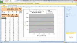
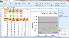
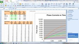
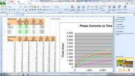
Arlo, here is a revised spreadsheet for you to play with. Input cells are the light green. I added three TBD Motor columns for your inputting. Titled Motor A, Motor B and Motor C. Let me know if it doesn't meet your needs.
View attachment MotorCurrentsV2.ZIP
View attachment MotorCurrentsV2.ZIP
whatever
100 kW
- Joined
- Jun 3, 2010
- Messages
- 1,297
dont forget that alot of this sort of work has already been done in other motors, one example is csiro solar car motor, which has no iron core and must use inductors in order for controller to function ( might aid understanding seeing what other have done )
Very good point I must admit this is something suggested to me by luke in the first place and I was to stubborn to listen. But 3 blown controllers on collossus later.....whatever said:dont forget that alot of this sort of work has already been done in other motors, one example is csiro solar car motor, which has no iron core and must use inductors in order for controller to function ( might aid understanding seeing what other have done )
Lol the funny thing is earlier I was wondering what the negative spike was on the oscilloscope then I realized while I was showering that it was the stored energy in the inductor feeding into the motor! SO cool to see it in a visual form on the oscilloscope!
Another thing I am looking at is how much the timing will be retarded. So at 7000 rpm collossus has 70,000 erpm and that meens one erevalution would last for .00085714 seconds. Knowing that if my inductor retards the signwave by 8 useconds then that would be about 3.4 edeg. From my calculations. 16us would be 6.8 edeg ect.
Thank you so much for this big moose this is helping me est where I should go. I took a few screen shots to show 80volts 96 volts and then I tried adding the resistance of 2 15uh inductors (two in series with 14 awg wire) and you can see the inductance plays a far bigger roll in the phase amp limits of a motor! I also rescaled the time to go from 5us up in 5us increments.bigmoose said:Arlo, here is a revised spreadsheet for you to play with. Input cells are the light green. I added three TBD Motor columns for your inputting. Titled Motor A, Motor B and Motor C. Let me know if it doesn't meet your needs.
Attachments
Ineresting to see 3x 100uH inductors on the csiro set up.whatever said:dont forget that alot of this sort of work has already been done in other motors, one example is csiro solar car motor, which has no iron core and must use inductors in order for controller to function ( might aid understanding seeing what other have done )
http://www.csiro.au/resources/pf11g.htmlï® The motor can be interfaced to a wide range of controllers, a typical installation is
shown below. Also see section ‘Motor Controller’. Note, the diagram does not show
user interface connections, soft start circuitry, or status information connections. The
number and type of user interface and status connections will depend upon the
controller. Whether a soft start is required will also depend upon the controller, note
the CR20-75 requires a soft circuit (see controller manual).
CR20-75
3 × power
connections
Screen
(connected
to GND at
each end)
3 × 100 μH
Safety earth connection via axle
2 × temperature connections
5 × position
connections
CSIRO
UTS
motor
Figure 1. Power and control connections for Unique Mobility CR20-75 Motor Controller, note soft
So I took the 8 useconds that I measured the inductors really limiting the amps and divided that into 60 useconds that I measured as max on time in all my tests for the PWM and got 7.5 so to me that would mean I will need a total of 7.5 x 15 uH inductance which = 112.5 uH per phase. So does that mean I add the two inductors on the phase together? Because one is on the positive pulse side and one is on the negative pulse side. If so 55 uH inductors would be a place I would start and work down from....
I think the only downside of having a bit too much inductance is the added resistance in the coil.
If the CSIRO guys used 100uH, then I bet that would be a good target value.
Yes, since two phase wires are active at any given time, you'll have 2x the value of each inductor.
Now, how many turns do you need to get 100uH?
If the CSIRO guys used 100uH, then I bet that would be a good target value.
Yes, since two phase wires are active at any given time, you'll have 2x the value of each inductor.
Now, how many turns do you need to get 100uH?
For testing I am just using 14 awg on a piece of 1.875od pvc pipe. I linked a air core multilayer calc in the thread but here it is again. http://www.pronine.ca/multind.htm So if I wound 1 inch off the pipe I would have 3 layers of winds and 45 turns and use 23.59 feet of wire. But if I wound it for .198' I would have 31 total turns and use 20.04 feet of wire. Thats all for a 100uH inductor.... I think if I start with 50uH inductors I will find I can work down from there. The CSIRO guys have a iron-less motor collossus has iron so it will have some inductance.... The total inside the CSRIO is 20uH and they say that a controller needs ~120uH Which is not far off from my 112.5uH measured and estimated with my oscilloscope!fechter said:I think the only downside of having a bit too much inductance is the added resistance in the coil.
If the CSIRO guys used 100uH, then I bet that would be a good target value.
Yes, since two phase wires are active at any given time, you'll have 2x the value of each inductor.
Now, how many turns do you need to get 100uH?
rhitee05
10 kW
Not sure I really follow how you made the inductance measurement with your scope. The usual way (the way that I teach my lab students) is to measure voltage/current at two instants of time, then those two measurements plus the delta-t can be easily used to find the time constant. Knowing R, the time constant will give you L. In your case, one way would be to apply a brief pulse of current and then make the measurement on the decreasing side. I mention this because I don't think I really believe the 112 uH number. Along with the 9.3 milliohm resistance you measured earlier, that would put the time constant at 12 ms which would make it easy to control. Since that's not the case, at least one of those measurements is suspect.
With these inductors you'll have to include the wire resistance when you calculate how much inductance you need. 24' of 14 AWG is about 60 milliohms, which is already 6x the phase-to-phase resistance you measured earlier and obviously non-negligible. That'll have a big impact on how they affect the motor since the time constant is L/R - bigger R makes the time constant smaller which isn't what you want. You'll need more inductance to compensate (how much depends on the inductance of the motor).
With these inductors you'll have to include the wire resistance when you calculate how much inductance you need. 24' of 14 AWG is about 60 milliohms, which is already 6x the phase-to-phase resistance you measured earlier and obviously non-negligible. That'll have a big impact on how they affect the motor since the time constant is L/R - bigger R makes the time constant smaller which isn't what you want. You'll need more inductance to compensate (how much depends on the inductance of the motor).
I guess what I meant to say fecher is do you think the stored energy comes back from both inductors? Its my understanding electrons flow from negative to positive and only one direction though a circuit so when a phase is energized the negative fets will feed one inductor then through the motor then into the other inductor and back into the positive fets. But when the phase is shut off then inductor on the negative side will feed the motor but the postive side inductor will try to push current to the positive fets. So I am wondering if the second inductor is a loss of power?fechter said:I think the only downside of having a bit too much inductance is the added resistance in the coil.
If the CSIRO guys used 100uH, then I bet that would be a good target value.
Yes, since two phase wires are active at any given time, you'll have 2x the value of each inductor.
Now, how many turns do you need to get 100uH?
What I looked at with the oscilloscope was the voltage drop across a 15uh inductor hooked in series with my x5304 All I was looking at was voltage drop vs time and found they dropped a lot at first and very little after 8 Useconds After 20 Useconds you could see a perfectly flat line so the inductor was done building its magnetic feild but from the 8uS to the 20uS mark it was a very very very small change. And yes I I'm considering resistance losses. All I am trying to do at this point it build a set of inductors that don't let another controller pop then from there I can allways take turns out till I find the magic number for my setup!rhitee05 said:Not sure I really follow how you made the inductance measurement with your scope. The usual way (the way that I teach my lab students) is to measure voltage/current at two instants of time, then those two measurements plus the delta-t can be easily used to find the time constant. Knowing R, the time constant will give you L. In your case, one way would be to apply a brief pulse of current and then make the measurement on the decreasing side. I mention this because I don't think I really believe the 112 uH number. Along with the 9.3 milliohm resistance you measured earlier, that would put the time constant at 12 ms which would make it easy to control. Since that's not the case, at least one of those measurements is suspect.
With these inductors you'll have to include the wire resistance when you calculate how much inductance you need. 24' of 14 AWG is about 60 milliohms, which is already 6x the phase-to-phase resistance you measured earlier and obviously non-negligible. That'll have a big impact on how they affect the motor since the time constant is L/R - bigger R makes the time constant smaller which isn't what you want. You'll need more inductance to compensate (how much depends on the inductance of the motor).
As for the 14awg it is only to test with as I have already stated I am most likely going to use dual strands of 10awg to get the resistance down as much as possible to get the heat down too.
Without an LCR meter, to accurately measure the inductance of your coil (and/or the motor) I think you will need to simultaneously sample both the rectangular voltage and triangular current waveforms over a PWM pulse. What do you have available for a current sensor? Do you have a current clamp for your 'scope? Or some spare shunt wire? Or you could build a current transformer if you have a large enough toroid hanging around. Or you could even build a toroidal core out of some steel or iron wire.
The voltage drop will tell you current. Or an estimate. The more drop the less current. Like fecher and a couple others pointed out if you get a flat spot in the mesurement it is not enough inductance. Which is what you can see with the pics I posted. I would like to find a LCR meter but that will be a month or two.jdb said:Without an LCR meter, to accurately measure the inductance of your coil (and/or the motor) I think you will need to simultaneously sample both the rectangular voltage and triangular current waveforms over a PWM pulse. What do you have available for a current sensor? Do you have a current clamp for your 'scope? Or some spare shunt wire? Or you could build a current transformer if you have a large enough toroid hanging around. Or you could even build a toroidal core out of some steel or iron wire.
liveforphysics
100 TW
Arlo1 said:The voltage drop will tell you current. Or an estimate. The more drop the less current. Like fecher and a couple others pointed out if you get a flat spot in the mesurement it is not enough inductance. Which is what you can see with the pics I posted. I would like to find a LCR meter but that will be a month or two.jdb said:Without an LCR meter, to accurately measure the inductance of your coil (and/or the motor) I think you will need to simultaneously sample both the rectangular voltage and triangular current waveforms over a PWM pulse. What do you have available for a current sensor? Do you have a current clamp for your 'scope? Or some spare shunt wire? Or you could build a current transformer if you have a large enough toroid hanging around. Or you could even build a toroidal core out of some steel or iron wire.
In the case of an inductor, voltage drop can't show you current anymore, while it's charging or discharging.
Similar threads
- Replies
- 1
- Views
- 639
- Replies
- 45
- Views
- 3,807
- Replies
- 8
- Views
- 1,096
- Replies
- 479
- Views
- 49,049
- Replies
- 66
- Views
- 12,783