Inductance What is it what does it do? Collosus has 8uH!

liveforphysics said:
In the case of an inductor, voltage drop can't show you current anymore, while it's charging or discharging.
What about the voltage drop across the inductor it self (not a motor with magnets but the inductor alone.)?
If current is not flowing though would the resistance not be higher causeing a higher voltage drop? Then as the feild builds the resistance drops causeing a lower voltage drop and more current to flow?
 
fechter said:
Another way to measure would be to look at the waveform on the phase wires during switching with an oscilloscope. You can see if the slope starts to flatten out toward the end of the cycle indicating not enough inductance.
 
http://www.pa.msu.edu/courses/1997spring/phy232/lectures/induction/self.html

Inductance

The Inductance L is a measure of the voltage drop across an iductor (e.g. a solenoid) per the rate change of current.


Since the magnetic field inside a solenoid is proportional to a current, the rate-change of the magnetic flux is proportional to the rate-change of the current. From a previous lecture, the magnetic field inside a solenoid was given as:
 
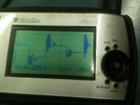
Measuring the voltage across the inductor is not a very good way to do this, even for a "is it enough" measurement. If the motor inductance is really low, the external inductor voltage will go to zero when the motor current levels out. However, If there is enough inductance, the voltage across the inductor will also be fairly low because the current isn't changing very fast.

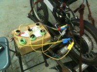
You really need a purely resistive element to measure current across, or a hall-effect "clamp" probe. Otherwise you can't separate the V=IR voltage from the V=L*dI/dt voltage. A straight, non-coiled length of wire would probably be sufficient if your scope is sensitive enough to measure the voltage.

If you want to get an accurate measurement of the inductance value, you need to measure the current at two points during the transient. One point close to the PWM edge and the second point after it's at least 50% is best. Those two values and the delta-T between them will let you calculate the time constant. Just measuring the time to decay to approximately zero is not sufficient to get any kind of accuracy. It's not a difficult measurement to do, it just needs to be done properly to get an accurate result. Look up "RL Circuit" on Wikipedia for the equations and such.
 
Ok I need to clear one thing up I am looking at the pulse width and comparing the length of voltage drop across the inductor to see if it is enough and that is all at this point. I have numbers I have seen the controller produce for pwm on-time in the middle of 1/2 of the sign wave and they range from 5-60 uS so I want the inductor to be able to ramp up for a length of time maybe as long as 60 uS. So far what I see is a very fast ramp up by 8 uS I would say I want way more inductance to start with then work back down from there. The thing with my controller is it uses a battery current to guess at phase current so I need it to have enough time to regulate properly (or as best it can) before the inductor passes full current and just pops more fets!
 
You need the ramp up time to be significantly longer than the PWM period for the controller to keep a handle on the current. Like 2-3x longer. So lots more inductance!
 
rhitee05 said:
You need the ramp up time to be significantly longer than the PWM period for the controller to keep a handle on the current. Like 2-3x longer. So lots more inductance!
Hmmm thanks for the tip.

What do you guys think about this? http://electronics-diy.com/store.php?sel=kits
 
Or this http://cgi.ebay.ca/High-precision-Inductance-Capacitance-L-C-meter-LC100-A-/270774579062?pt=LH_DefaultDomain_0&hash=item3f0b6c2f76
Or this... http://cgi.ebay.ca/LC200A-Inductance-Capacitance-L-C-Multimeter-Meter-Tool-/300576532444?pt=LH_DefaultDomain_0&hash=item45fbc1e7dc
 
I don't know anything about those meters, but they would probably work fine.

You don't necessarily need one, though, you can make the measurement just with your scope and what you've been doing. You just need to use a resistive shunt and with good technique you'll get a reasonably good value.
 
rhitee05 said:
I don't know anything about those meters, but they would probably work fine.

You don't necessarily need one, though, you can make the measurement just with your scope and what you've been doing. You just need to use a resistive shunt and with good technique you'll get a reasonably good value.
Ok I do have a shunt I built back with a lenth of 8 awg and multi meter plugs on each end it mesures voltage drop and I think on the milivolt scale with your meter it shows amps I made it 10 years ago and forgot I had it. SO you are saying that I want to just put it in series with one phase and test it?
 
But rhitee... What I was really hoping to do was see how fast one inductor would build up on its own. Big Moose's spreadsheet is pretty handy for all of this for total amps in the whole system vs time vs inductance and resistance for a given voltage. But I would like to start with a fair bit of inductance added to collossus (which must have some) and work down from there. I still think a total number of 112.5uH for the whole system should be very close and in that case 50uH per inductor should help get me started!
 
Ok back to my question. Does anybody know if the energy stored in both inductors will feed the motor? As far as I can tell the second inductor in every set will just be wasted energy because electrons flow only one direction....
 
Arlo1 said:
Does anybody know if the energy stored in both inductors will feed the motor? As far as I can tell the second inductor in every set will just be wasted energy because electrons flow only one direction....

This statement is very badly off on basic electrical theory.

I assume what you're referring to is the common convention that we label currents as flowing from positive to negative. This doesn't say anything about what direction the current is actually flowing - it's just a definition so we can keep our sign conventions straight. This is called the passive sign convention and it ensures that if you calculate P=V*I, a positive number means power is being absorbed and a negative number means power is being produced. That's it! The sign of current can be positive or negative and we have to apply circuit analysis to figure that out. Incidentally and to confuse the subject further, this convention is opposite the actual direction that electrons will be flowing, but that's how current has been defined. We stick to these definitions to keep from being confused.

As far as energy stored in the inductors, as a reactive element a ideal inductor cannot absorb power. A real-world inductor will absorb some power in the internal resistance, but the energy in the magnetic field (E = 1/2*L*I^2) is merely stored and released. The inductor absorbs energy (into storage) as current increases and releases energy as current decreases. The same is true for capacitors and electric fields.

Arlo1 said:
But rhitee... What I was really hoping to do was see how fast one inductor would build up on its own. Big Moose's spreadsheet is pretty handy for all of this for total amps in the whole system vs time vs inductance and resistance for a given voltage. But I would like to start with a fair bit of inductance added to collossus (which must have some) and work down from there. I still think a total number of 112.5uH for the whole system should be very close and in that case 50uH per inductor should help get me started!

If the goal of the experiment is to measure the phase inductance of the colossus motor, the best way to do that is with the motor alone and no external inductors. If you want to/have to use external inductors, you will have to set up a measurement first using only those external inductors so you can get a good measurement of their inductance. Otherwise you won't be able to separate out the phase and external values.
 
Ok so I have a dual trace oscilloscope coming and a couple of those cheep indctance and capacitance meters coming as well. I will try to get a reading from the x5 and collossus and see what the difference is. What I was asking about the stored energy is in the system there is a inductor before each phase wire. So when the phase energizes the inductor builds a magentet feild and amprage increases as it builds but when the phase UN-energized both the inductors taper off continuing to relase their energy that was stored in a magnetic feild so if there is one inductor on the positive side of the phase and one on the negative side they will both want to flow current the same direction but only one has a motor after it..... So from what I can tell only one will give the rest of the power to the motor the other is tring to feed current to the controller.
 
Putting an external inductor on each phase is no different than if the phase inductance was higher to start with. When the PWM pulse goes low, current will continue to flow through both inductors and through the freewheel diodes in the controller as the stored magnetic energy slowly dissipates into the motor. One of them doesn't suddenly flip directions, current through an inductor cannot change instantaneously.
 
rhitee05 said:
Putting an external inductor on each phase is no different than if the phase inductance was higher to start with. When the PWM pulse goes low, current will continue to flow through both inductors and through the freewheel diodes in the controller as the stored magnetic energy slowly dissipates into the motor. One of them doesn't suddenly flip directions, current through an inductor cannot change instantaneously.
Ok thats enough of a answer for me to think i understand lol
 
rhitee05 said:
One of them doesn't suddenly flip directions, current through an inductor cannot change instantaneously.

it may help to remember that the power flow through the inductor is proportional to dB/dt, itself proportional to dI/dt. It is the change in sign of dB/dt that changes the power flow. During the off portion of the cycle, current is flowing through a loop: inductor, motor, inductor, diode. Both inductors are in the same loop. Changing the order of the circuit elements within the loop doesn't actually change the current or voltage drops across any element in the loop.

If you change your point of reference to be one terminal of the motor instead of the diode, then both inductors are either "before" or "after" the motor. But their behavior is the same in both cases, because the topology is identical.
 
this paper by csiro motor guys, has some info re: inductance with controller and csiro motor
( by the way each inductor they use is 1.1kg! so 3.3kg all up)
 

Attachments

  • csiro mosfet motor circuit.pdf
    309.4 KB · Views: 89
whatever said:
this info from old es pos[/attachment]
If you read the whole thread I already linked to the CSIRO stuff.
 
Ok so I wound a set of what should be 35 uH inductors and hooked them in series with my 15 uH inductors I then hooked them to the bmx and tried to get some more readings.
What I found was no mater where I mesured in the system the time was the same always 25 Useconds which before was just 8 Useconds
 

Attachments

  • 031_renamed_13022.jpg
    031_renamed_13022.jpg
    43.8 KB · Views: 1,866
So now I have a 4ch oscilloscope coming and a couple cheep inductance meters. What do I need to look for before trying collossus again? Tomorrow night I will hook up my last 24 fet controller and try running it with 50uH inductance hooked to each phase wire.

But if I was to guess I could even use 100 uH on the bmx it looks to me like the X5 doesn't have enough inductance and all that is saving our controllers is the low kv and high resistance. I will pull out my shunt I made for measuring hi amps tomorrow as well and see what I can see from it.
 

Attachments

  • 019_renamed_4002.jpg
    019_renamed_4002.jpg
    71.8 KB · Views: 1,866
mr italiano the pdf file I posted is not linked to the csiro site, took a bit of searching to find that article, I cant be bothered cut and pasting the info relating to the inductors but its a damn good article as far as I'm aware it hasn't been posted on es before.
 
whatever said:
mr italiano the pdf file I posted is not linked to the csiro site, took a bit of searching to find that article, I cant be bothered cut and pasting the info relating to the inductors but its a damn good article as far as I'm aware it hasn't been posted on es before.
Oh Im sorry man.
I didn't realize. All I was looking for was numbers of total system inductance and motor inductance ect.
 
Just to point out, inductance by itself doesn't matter. It's the L/R ratio that matters. Two motors could have the same inductance but different resistances, and one of them will be easy to use and the other will smoke the controller instantly.
 
Back
Top