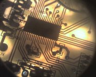
INFINEON CONTROLLERS FOR DUMMIES

solarbbq2003 said:
chip info
http://www.infineon.com/cms/cn/product/ ... 5ce2eb6a27
solar well done, you get an award for that.
Geoff
 
Have you guys got a different chip in your Infineon controllers? Mine appears to be an XC846, not an XC864.

The reason I ask is that I made the same mistake that Brett seems to have made and assumed that the "846" in the original Infineon title thread was really a typo and should have been the "864". Since looking at my board I've been able to confirm that the chip is really the 846............... (as someone pointed out to me a few days ago on here)

Jeremy
 
Jeremy Harris said:
Have you guys got a different chip in your Infineon controllers? Mine appears to be an XC846, not an XC864.

Hahahahahaha... :oops:

Jeremy is absolutely correct. I think I fell into this trap when I went looking the first time. There's no doubt that this is a "family" of chips, but the EXACT specifications of an 846 versus an 864, then, remains a mystery. Kinda like knowing the difference between PICs in a given family (how much memory, number of ADC, PWM, UART, etc.). They all execute the same code, but the "peripherals" available sets 'em apart. It's quite likely that the chips in the XC800 family are pin compatible, though...
 
so do I get to keep the fried guinea pig? whats happened to knuckles? did he go back to mars? I thought he was an alien, he knew too much!
 
hi
this is my fault after doc posted the xc866 chip pinout when solarbbq posted the xc864 I saw the right numbers but got them the wrong way round.
solar for getting closer than anyone else has so far I think you should keep the award.

for not checking things more closely first I award myself the inverse fried guinea pig award :oops: :oops: :oops:

Fried_guinea_pig3.jpg

all may not be lost the information may be similar I have some fried 12fet boards and a magnifying glass I will find out what connects to where see if we can male some sense of it all since a data sheet is not forthcoming.

Geoff
 
That's why this is the "Dummy" thread. :mrgreen:

I saw the XC864 and figured you guys were just talking about yet another infineon controller.

Also, in reference to an earlier post, someone mentioned +12V going to the EBS pin, apparently for brake lights to also cut the controller output. My 15 fet Infineon with controllers with XC846 MCU's come stock with a single wire for brakes. The factory guy tells me that wire expects 12V, but it is connected to the BK pin, not the EBS pin.

Also, in the other infineon threads mention is made that the regen limit is 60V. My controllers are 60V controllers, so is that standard 60V a hard limit, or would it work for 60V nominal (ie a 71-72V peak)? I realize you guys are confident and probably think "just give it a try to find out", but with me a negative result will have zero meaning.

John
 
John in CR said:
That's why this is the "Dummy" thread. :mrgreen:

I saw the XC864 and figured you guys were just talking about yet another infineon controller.

Also, in reference to an earlier post, someone mentioned +12V going to the EBS pin, apparently for brake lights to also cut the controller output. My 15 fet Infineon with controllers with XC846 MCU's come stock with a single wire for brakes. The factory guy tells me that wire expects 12V, but it is connected to the BK pin, not the EBS pin.

Also, in the other infineon threads mention is made that the regen limit is 60V. My controllers are 60V controllers, so is that standard 60V a hard limit, or would it work for 60V nominal (ie a 71-72V peak)? I realize you guys are confident and probably think "just give it a try to find out", but with me a negative result will have zero meaning.

John
hi sorry about that. I said about the +12v going to ebs+ on the board a closeup of the underside of your 15fet where all the markings are would help to clarify things.
Regen is hardwired into the chip set at a nominal of 48v so has a cutoff value of 60v, this we think is because originaly the controllers were sold ready built by the factory in china to the chinees the caps that werwe fitted were 63v caps to have regen work over 60v would blow them up so a "safety valve" was probably fitted cutting regen with batteries over 60v, we asked if the value could be changed but so far it is a no go situation. for those wanting regen over 60v knuckles has worked out a modification that can be fitted or if bought from him he will fit for a price.
i will edit and add the link to the modification but it will be in the regen thread somewhere.

Geoff
 
Thanks, let me know if a better pic is necessary.

15fetInfineonclose.JPG


15fetInfineon.JPG
 
Dang, solar... That's just enough information to be intriguing.

As always, a little information leads to other questions... This takes us as far as showing how to attach a connector for the alarm system (I'm thinking that the thing on the right is just a Molex-style connector). What does the REST of the circuit look like, I wonder. I'm thinking that the Golden BAC-28x will look EXACTLY the same. Will dig that out...
 
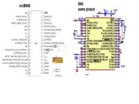
just a note to say 866 chip pinout posted earlier ( by someone sorry cant remember who it was), and 846 are identical,
also attached is google translation of alternate brand using same chip,some explanations of functions, translation is bit 'iffy' but good enough. will post some pics of that circuit geoff as time permits, quite a few customers waiting on gear for a long time have to sort that out or i'm stuffed,not much time for messing around for a while
View attachment 846 alt brand blurb.doc
846 pinout.jpg
 
I'd just managed to reach the same conclusion, Brett, by digging around on the Infineon site (as posted here: http://endless-sphere.com/forums/viewtopic.php?f=2&t=9191&start=165#p150341 ).

The XC846 in these controllers is a ROM only version of the XC800 series microcontroller and is not internally identical to the XC866. That linked post above decodes the part number and another link on that post takes you directly to some application information and code for driving brushless motors with this chip.

It looks as if the primary difference between the XC866 and the XC846 is that the XC866 has it main firmware in ROM, rather than in flash memory. This may or may not be one-time programmable, I haven't had time to dig through all the documentation to find out yet.

Jeremy
 
the controller on my 9FET infineon has 60842 printed across the end. i assumed it is an earlier version of the processor. the pinouts look identical to the pcb that drbass photographed on the 18FET thread. everything was identical except the caps, and the FETs.
 
thanks jeremy
had a read of the other threads, sounds like its only the 18 fet board is a bit problematic, looks like there is a 2k flash on the other boards using 846, well hope i'm reading it right, would that be correct, the 6 and 12fet boards are ok to store changes via program? or is it the case if they have 846 then it just wont remember the settings?
 
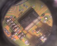
heres pic of the 846 markings in the 12 fet boards from xie cheng hope they have flash memory
(boards not from keywin just direct from xie cheng)
looks like markings are F-xc846 1fri-ab
I'm definitely sticking to the 'dummies' thread looks like some guys going to disappear into the world of coding chips, I think a bit beyond me.
12fetinfineon3.jpg
12fetinfineon4.jpg
 
The markings on that chip are exactly the same as those on the XC846 in my other 18 FET controller.

I'm pretty sure that all these controllers use the same chip and same internal code, as all of the external circuitry seems pretty much the same. I can't see any good reason for them to switch chip types between different models, so would expect teh 18 FET boards to be as programmable as the 6, 9 or 12 FET ones.

All variants of the XC800 series chip seem to have some flash memory, but the XC846 has it's lower programme bank of memory as plain ROM. My guess is that the primary firmware is stored in ROM, and can't be changed by the user, whilst some settings, like the current limit, LVC, speed limits etc are held in flash memory so they can be changed using the programming connection. That would make a lot of sense, as otherwise there would be a chance that users (or dealers) could brick the board by messing up the main firmware when programming the controller.

Jeremy
 
This all lines up with my original assertion that these chips are purchased from some outfit pre-programmed. I hit a couple of Chinese forums that refer to the thing as an "electric vehicle controller", and it would seem that there are numerous different boards built around it by different manufacturers - it also explains why there are pads and functions on the "e-bike" version that really have limited value in this context.

Still would be nice to know what the code was DOING, though...
 
hi
I can't help with the code but I am doing my best to find out as much about all the pads and settings as possable. I've seen just how dangerous the soft start can be in a problem so I have got keywin to get back in hard start in 12 and 18 fet models.
As for all te pads and stuff i am slowly going through them identifying and cataloging them, I still have a way to go and I could do with help from you Philf on the rpm/speed part and how to get a correct responce.
Geoff
 
not sure if this helps, but many moons ago, there was discussion on soft start I think for crystalyte controllers,
I think from memory it involved changing a cap value ( might have been resistor), I wonder if there is a non chip solution for the infineons also?
 
quck search came up with this from bob mcree , no idea if it helps
by bobmcree » Fri Nov 30, 2007 4:10 pm
on the throttle input stage in the crystalyte controllers there is an op amp that subtracts a volt from the throttle signal and then amplifies it so that 1-4v from the throttle is turned into 0-5v before it is fed directly to the soft start cap on the pulse width modulation chip. the output of this chip is fed to a logic gate where it is combined with the motor drive pulses to achieve pwm control of the high side fets. the low side fets are just turned off and on.

the pwm chip is designed to be used a bit differently than the way the crystalyte designer implemented it. there is a feedback amp in the chip that could be used for current feedback to get better motor control, but instead they used that circuit for low voltage cutoff and current limiting. as a consequence, the output of the pwm is directly proportional to the voltage on the soft start cap. the conditioned 0-5v throttle signal is applied directly to this cap, and the ebrake can pull down the cap voltage through a diode. the cycle analyst pulls down the ebrake signal to achieve power limiting, as does the current mode throttle design fechter posted.

reducing the value of the soft start cap which is connected to pin 8 of the ka3525 pwm chip will speed up the ramp up of the pulse widths under all conditions, including the one where you switch the unit on with the throttle stuck on. playing around with the throttle voltage as a function of position can change the throttle response curve a bit, to make it more linear.

when looking at the voltage on this cap be aware that there is an internal circuit on the 3525 that can pull it down when the shutdown signal is asserted on pin 9 by the circuit that tells it the motor is not turning. this can be confusing at first. if you reduce the value of the cap too much you can let the pwm go to full on before the controller "realizes" the motor is stalled and blow a lot of fets as a result. be cautious.
 
seems the controllers have self learning function also, pat6-2 to ground puts in self learning state, means to match to a motor only need to swap the thick phase wires colours till motor runs ok, no need to mess with hall wire combinations, disconnect pat6-2 when correct combo of phase wires, and it remembers the setting, saves going through all 36 combos.
 
Back
Top