Why I need a 5 amp balancer is for used and tired lfp from Battery Hookup.
It is why their 8 Ah Headway cells were only $5 each. Now $5.50. I also bought 26650 cells when they had them. They seem to be a little more stable ; but the Headway cells not so much.
I got rid of the 6 Headway cells that I salvaged from the fire as even under a 1 or 2 amp load from 12V lights. The voltage dropped to around 6V after running the lights for a few hours. Was not me running them though so not sure but better safe than sorry.
I built a 3S - 3P Headway pack from the cells left over that did not burn but tested < 4 Ah when I got them from Battery Hookup. I have two 5S - 8P packs from 26650 cells and one 7S - 8P. All the same cells - 2.5 Ah - A123 cells.
For 56V I run 17S - 8P but for 43V I want to run the two 5S packs with the 3S Headway pack wired in series between them. Even at 3P those 8Ah Headway cells are the weak link so know better to run them too far without stopping and checking voltage with a balancer. I have not run the 43V yet but did run the 7S and 5S for 12S lfp. I need to finish installing 3 amp fuses to all the balance wires on the second 5S pack.
Obviously I wont be able to run a 5S active balancer with 3 amp fuses so will need to external balance. I used to run LiPo a long time ago so still have two 6S and two 7S external balancers. If I set the charger for 2.5 amps the external balancer seems to work but sometimes have to shut down the charger and let the balance catch up.
I only plan on running these batteries < 5 miles a day , Maybe 8 miles with the 17S - 8P packs but <5 miles for 13S with those Headway cells .I need better quality lfp cells, preferably brand new. At that point I plan on running a Bluetooth BMS and was considering a 5S active balancer but may not need it if the cells are really brand spanking new.
It is why I posted the link to those cells on my last post. I was hoping someone might have an idea if they are in fact brand new or garbage like battery Hookup sells.
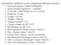
HEADWAY LIFEPO4 38120S 10000MAH SPECIFICATIONS Nominal capacity: 10Ah(10,000mAh). Initial internal impedance: < 4mOhm.
www.ebay.com
It states new but tested ??? Hope someone might know.
Thank you for your post. I am not a Greenhorn but not an expert either. Somewhere in between. I have been at it a few years. Started with SLA then LiPo and Lion. Then after watching fires on YouTube and that video I switched to lfp.
Dangerous vs. Safe batteries, Explosion and fire test! I tried posting the link but did not work.
. I am kind of distraught since the fire. Would have been a lot worse if Lico or Lipo. Batteries did not ignite. just balance board and plastic case. Also mad as I paid over $100 for a 54.6V 15 amp lfp charger and about $70 for a 43.6V 10 amp charger from ali express which I will no longer use unless I can get new and stable cells to build a pack and expensive Bluetooth BMSs with active balancers.
Reverse polarity is way over my head and may never understand how that could even happen. I removed all active balancers but if I do use them again it will be when charging , not running and will extend the balance wires about a foot and place the balancers in a large glass ash tray. lol Thing is , it may not have been the balancers fault since reverse polarity caused the fire but they are still cheap and made in China so suspect.
I wish I had got more college time in as the method used for charging all lithium battery types just makes no sense. If I were to design a charger and BMS I would install a 15 amp fuse holder next to the BMS and all balance wires would be 16 gauge and when a cell reaches its full state of charge the voltage of the charger would drop equal to the fully charged cell. So if it was a 15S charger for example the last two cells would be 2S voltage and the last 1S. It would be impossible to over charge a cell.
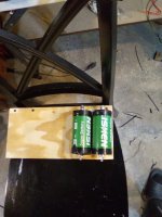
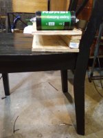
For discharge the BMS would active balance from the top down at 5 amps. I am currently charging at 0.1 amp by hooking the balance extension wires to bolts. I drilled holes in a piece of trim so I can just charge the lowest cell in that 3S Headway pack.
It is extremally difficult to balance charge lfp with a 6S LiPo charger. It does not want to fully charge a pack.. The charger reads FULL with a cell about 3.38V and a cell at around 3.5V and a cell at 3.7V or higher. The external balancer does an even worse job. It is ridiculous.
For my 7S - lfp pack with the 26650 cells I use my 7S external balancer and set the LiPo charger to 6S LiPo so 4.2 * 6 = 25.2V / 7 = 2.6 charging volts. I will need more 7S balance wires and an extra bolt in the stick of wood for the 7S pack. LOL.
Looking at getting a new charger from Hobby king. If I can get the packs balanced then hopefully I will be able to use my 10 amp and 15 amp chargers when I am out riding again.
ToolkitRC M9 1~8S 20A 600W DC Multifunction Balance Charger/Discharger. Hobbyking for the best deals in smart chargers, ac/dc chargers, and lithium batteries.

hobbyking.com
Thing is , it only balances at 1 amp. Good for new perfect cells if I get them but not for older cells with different capacity. I will need 5 amp balancers with 5 amp chargers and 10 amp fuses to all balance wires. That will cost a lot of $$$$$.

Then there will be a lot of extra work. I no longer trust active balancers or BMSs unless they are Bluetooth. I need to actually see all cell voltages from now on. I could still use active balancers but the plugs for those balancers will not plug in to my external balancer or the charge port on the charger. The active balance plugs are smaller with the pins and holes closer together. I will have to order balance plug extensions and cut each wire and wire up the plugs for the active balancers. Then I can check voltage with a meter before discharging to make sure the balancer did its job.
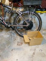
I rode around with the 43V set up and external balancer on board. 5 or 6 miles or so from about 60% to 30%. I could monitor cell voltage while riding. If I only charge from 20% or 30% to > 60% < 70% the cells seem to not require balancing. A full fast charge will sky rocket some cell voltages which is unacceptable to say the least.
The 5 in 1 cell checker/balancer is cheap but 7S. I charged at 10 amps for around 20% to > 50% Highest cell maybe 63% but all 50% or greater. It took the 6S RC LiPo charger about 14 hours to get those 3S - 3P Headway cells to get to 3.6V before that though.
My conclusion is you can get a lot of cycles off of used lfp but charging 13 to 17S lfp with a 6S LiPo charger is not the ideal SHITutation. Needed initially to get total balance but then keep doing 20 to 60% charges for minimal balancing. Might be able to get > 1,000 partial cycles though. Charging 13S lfp with a 12S lfp charger is actually better for old used cells as not such a sky rocket effect of a couple or more cells. Brand Spanking new lfp cells can discharge to 2.5V and fully charge to 3.65V. That would be < 0% to 100% even Steven cells. NO or minimal balancing. Not the case with used/OLD lfp.
You need to keep the charge and discharge curve a lot closer to 3.3V. Normal operating voltage for lfp cells. No lower that 3.1V preferably > 3.2V. Do not charge much greater than 60% as great risk of cells sky rocketing and throwing pack out of balance
12 * 3.65V = 43.8V / 13 = 3.369V.
Perfect charging voltage for old and used 80% or less capacity cells. I was hoping to hear some feed back on those nI ew 10 Ah cells from that link I posted from e bay. Also any other source for quality brand new or properly tested used lfp. When I spoke to the folks at Battery Hookup I was told they only check cell voltages. That makes sense as it takes a lot of time doing capacity tests and the cells are $5 or $5;50.
They did send me some replacements however so am not discouraging anyone from dealing with them. just expect to get what you pay for and use them like I stated above and can get some use from them. just do not expect them to hold up for a big road trip. Around 5 miles for cells that test < 50% in a 2 or 3P configuration and up to about 8 for the few cells testing around 70 to 75%. 2P. The A123 cells seem to be more stable at 60 to 80%. - 8P minimum. I would not go any less than that.
It is why I am seeking brand new. I would suspect the used cells probably have > 2,000 cycles or more or have been sitting on a shelf for > 10 years. With brand new 10 Ah - 1P should go 10 miles easily and still be > 3V per cell.
I will continue testing lfp under a wide variance of loads and charging methods and share the information here. I hope that it will be useful to someone. Please post any link for brand new lfp or used but properly tested for capacity. I would appreciate it.
.
Skyler.


.png")


.png")