RC Greyborg build thread

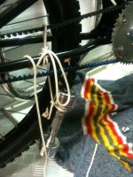
Mounted the chainwheel and used 1 washer behind the WI Freewheel to just move the inner Gates cog away from the frame, no rub any more. Elongated the holes in the torque plate to allow belt tension, not quite as much as I would have preferred. Gates recomend a tension that 5-10lb of weight at the mid point on the belt will create 1/2" of deflection, so that is what I aimed for.I used an Alan key wedged between the frame and the flat of the axle as a guage to tension the belt. 6mm seemed just too much and 5mm was not quite enough. I now need to remake the torque plate with the idea of the sliding tension arrangement, 12mm of adjustment should be all that is required and should account for any growth in the belt over time. I will probably make a matched pair to strenghen things up and for asthetics. Moving the wheel back in the drop outs 5.5mm seems to give the right belt tension, I think, maybe 6 or 6.5 maybe the magic number but I do not have that ammount of adjustment yet.
The only problem I foresee with this setup is changing a rear tyre will be a PITA as it will need the chain from the motor disconecting to allow the removal of the crank ring, before the belt can be removed. I just need to add a front brake, connect the Shimano gear cable, stick the pedals on and see what happens with some proper loading on the drive train. I have noticed a significant a mount of wobble in the freewheel at no load, spread over a wide chain ring this looks like 1/4" of play, which may be too much to live with since all the tolerances are quite tight. The Greyborg will definately be a moving bicycle this week.

View attachment 2Chainline Tightened.jpg
 

Attachments

  • Chainline Deflection Test.jpg
    Chainline Deflection Test.jpg
    60.3 KB · Views: 4,112
Managed to get the last couple of small jobs ticked off the list to make the rolling chassis. Front brake mounted, rear hub gear selector connected and taken for a spin round the local car park. I need to play with the gear cable settings to get all 11 gears to operate as they should but that should not be a biggy. I was happy to see it get this far at least :D 
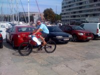
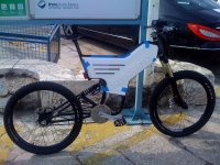
I am chuffed with the clean belt drive line, without having to install an idler, hopefully it does not grow significantly. The bike has 165mm crank arms, instead of the more standard 175mm variety, if ground clearance becomes an issue, it will be getting a 29er up forward. It does already remind me a bit of my old DT175 when straddleing the frame. I think I will get away with widening the canopy up forward, but close to the seat just rubs the tops of my inner leg, I might try to reduce that part of the canopy for comfort when pedaling.

Next on the list are motor mounting, battery building, enclosure modding, rear brake and sorting out the wobble that exists on the chain ring. It seems like the ISIS bottom bracket is bent slightly but it is brand new.

Front Brake Mounted.jpgView attachment 1
 

Attachments

  • Maiden Voyage Pedal.jpg
    Maiden Voyage Pedal.jpg
    98.4 KB · Views: 4,067
  • Rolling Chassis.jpg
    Rolling Chassis.jpg
    104.8 KB · Views: 4,067
Looking good mate. I can't wait to see it going with the RC drive, where are you going to put the motor/drive (apologies if you already explained this)?
 
Hi Phil

Great question and one to which I do not have the answer set in stone yet.... I had originally dry fit the motor and reduction in the bottom of the frame, which seemed to fit snugly, that was before I had the chainline setup. The adapter that holds the motor freewheel onto the redtucion drive protrudes about 1/2" past the teeth that the chain runs on, this stops it being used within the arc of the pedals. It could fit in the middle of the canopy but this spoils the space for the booster battery by splitting it. This leaves the very top of the lower frame section, which is the location I am leaning towards. It has a longer chain run, which might mean I can get away without an idler on the drive chain? I started making a mockup bracket in hammer bent ally last night but I did not quite get it right. I am going to try to have the drive unit mounted on a plate with horizontal elongated holes so that I can fine tune the drive line. this palte would then be mounted to another plate with elongated vertical holes to tension the chain. It's the next thing on the list that needs sorting.
 
comradegerry said:
sorting out the wobble that exists on the chain ring

if this isnt a product of the adaptor you had made from the freewheel to chain ring, I have noticed (and others have to) that the thread of the cranks is never quite centered. thus when freewheeling the chain runs smooth, but when the cranks are turning the chain changes length. This is with expensive Echo cranks so...... :roll:

Cheers
 
The adapter I made is flat, definatlely after it was machined at least, if I had the freewheel slightly off center I would expect it to oscilate a little up and down, not left to right... When I turn the crank arms backwards and it is freewheeling, the adapter is stationary but wobbles right to left as the crank arms turn. With the rear wheel off the floor and the crank arms turning forward the same wobble exists. It seems like either the bottom bracket spindle or as you sugest the thread on the crank arms, both were new and a bit spendy... I do have another set of ISIS crank arms I can fit and try to eliminate or confirm the spindle as the possible problem. Thank you for your input.
 
Yours looks so much tidier than mine....but I have done over 2,000 miles on mine in crappy UK weather :)

It's a shame the triple forks hit the body when turning tight. But it does ride like a Limousin...funny I see you have the same rear suspension that I had on my Greyborg....I took it off for a much cheaper but not so high one as my riding position was hurting my wrists. Now the pedals are too low doh!

Think I might cut off the seat and have it like a motorcycle seat that runs up the crossbar?

Nearly finished.jpg
 
And the slow plod continues....

Made what I think will be the motor and reduction drive mount, much bashing and drilling of Ti plate.

Having done the dry fit today, I now realise I have to chop a little bit of battery frame holder on one side and cut a hole in the mounting plate for the chain part of the reduction gear.

If it works like I hope I can likely sqeeze in another 10ah at 48v below the motor to give a 30 ah total which is the goal.

I am not 100% happy with the chain line and may try again to squeeze it into to the lowest part of the frame but this seems like it might work and I am just keen to get it powered up at this stage.

Frame mount 5.jpgFrame mount 1.jpgFrame mount 2.jpgFrame mount 3.jpgFrame mount 4.jpg
 
Spent the day trying to sort out the last few snags on the motor mount but did not quite get it done. Had to cut out a space for the chain driven part of the reduction gear, then elongated the mounting holes for the U shaped track to allow 10mm or 11mm of up and down motion to get the drive chain to the right length without an idler. Once the motor assembly moved upward I found that the belt pulley restricts the full movement do there will need to be some more frame filing tomorrow. Got it all together then found I had not made a hole for the motor wires to come out cleanly from the compartment, grrr. 8 hours spent drilling, filing and cursing for not much progress, it was an infuriating day. I think I might have to add a "power bulge" on the canopy just to conceal the chain wheel reduction, it is just too close.

Motor Frame Mount 4.jpg
 
Managed to get the motor finally mounted and lighten up one of the reduction wheels. I think it should work, I can turn the motor over by hand and the rear wheel turns so things look promising. Batteries next up on the to do list. Happy Halloween! :twisted:

Lightning 1.jpg Lightening 2.jpg Right Side Motor.jpg Left Side Motor.jpg
 
HAL9000v2.0 said:
This is great. Love how high you have monted it. Defintly better to put batteise below.
Why didn't you go with just belts?
Belts are wider than a chain for the same torque loading. So, as far as the drive system goes, that I why I went with a chain for the second stage. :)

Matt
 
Since the drive train seems OK, the batteries are the next on the to do list. I had an old duct tape pack from my old frock that is going to be sacrificed as the guinea pig and trial unit. Using a dremel with a cut off disc I broke the pack up into units of 3. I figure I can squeeze 3S 16p into the space below the motor for 48v and 9ah. After fitting the trial block and doing a bit more thinking I can see 4S 16P as being possible, so that is what I will aim for this evening. The old pack had welded tabs, the flap after cutting them open is where I plan to solder some bits of wire to reconnect it all again. Then hide the entire thing in more duct tape. It is a trial, if it works, sweet, if it does not, then I have the form mapped out can get a new battery made up. The top battery section will be a seperate 48v, 20ah cell block made of 38120 lifePo4 cells with 2 24v BMS.

What I do not know yet is how to switch between the packs on the fly but hopefully somebody smarter than me knows how to do it?
How to charge everything without having to take the canopy off. I was thinking of some kind of XLR connector flush mounted but could not find any weatherproof ones?
How to Isolate the batteries without taking off the covers and switching between them for charging?
I have a left handed half turn throttle and 3 position switch but do not know how to program the CA to set 3 current limits for legal/economy settings and "Off Road" applications. I was thinking 400w, 800w and 1200w as being the preferred set points, if that can be done like that? Controller is a 12 fet Lyen but have no clue if that is programable at some level?
Some sort of key to help stop the pikeys stealing it and zipping off with it when I have it leant against the wall of my favorite pub.

Old Battery.jpg Battery Trial Configuration.jpg
 
will you be using the CA as your throttle control? If so then you can have a top speed or top amperage programmed in. If you also have one of the programmable lyens conrollers, then msg him for the software link or grab the freeware from the forum (search keywin). Inside the software there is a speed section where you set your max speed (as a %) and then can set the three speed switch to three different %'s of that original total %. The total speed is just the kv of your motor* the volts of your battery=rpm*circumference of your wheel/ distance. The switch can be set from anything between 0 and 120%.
I love it too! Chain clearance seems pretty tight... but if it's solid and won't torque in the frame then it'll be great!
 
I will be using the CA as throttle control with top amperage programmed in as Andje sugests, probably 20 amps to start with.

I will be trying to program the Lyen controller and the 3 speed switch too, my head started to hurt when I read that thread, way over my head unfortunately, it will require reading a few times, slowly to sink in.

Built up the other pack to the format it will be, insulation tape in red and black at the ends of the cells to stop me making a booboo wiring them and also to just open the cells up a small bit for cooling plus to act as a barrier against chafing, these were all then hot glued together into 2 packs. The hot glue was just blobbed about 3/4" at either end on the tape but it seems pretty sturdy without going nuts. It is still possible to pull them apart if required as the insulation tape is the weak link, I already tested that when I assembled 1 slightly wrong. I Fluke tested all the voltages and they were real close which was great as they have been sat in my wardrobe 6 months already. The 2 packs mate together but are not bonded, the idea is 2 x 24v, 20ah each with an 8 channel BMS. Bought a copper sheet 12x12 on ebay and will make up the connection strips and shrink wrap what I can. Should get it wired this week, hopefully.

These cells were from Armin at LifeTech, he was a pleasure to deal with, very helpful and the quality of the cells seems top notch at least on first inspection. I just did not have the space to use the cell blocks and copper strips that came with them due to my space constraints.

I will be stretching the canopy up forward to 150mm wide to hide the batteries but since it is well clear of my knees I hope it is still comfortable to pedal.

View attachment 1 Final Battery Layout 2.jpg
 
Started wiring the batteries with some plate copper, slow work, got the first half done and will be working on the other half through the week.

After the rough fit and voltage test started to remove the excess copper with a file to lighten things up a little. Thank God copper is easy to file. :)

Batt wire 1.jpg Batt wire 2.jpg Batt wire 3.jpg
 
Hi Spacey, a Pikey would not know what to do with an ebike except pinch it, ride it till flat, then as you rightly point out flog it off as scrap and components!

I picked up an anti spark connector from ebay the other day, just not sure if I put it in line on the power out from the battery or wired in before the controller? it looks like a gizmo I need, just not sure how to integrate it :?:

Also picked up some Ebay Blood Line Trials cranks for $48, not as flash or light as the Echo SL but hopefully machined with straight freewheel threads, I could not live with the wobble at the cranks, that was only going to add excessive wear or cause premature failure in some part of the drive train. The Echos may hit the sale thread, not that they are any use for a powered through the cranks application.

http://www.ebay.com/itm/270831398347?ssPageName=STRK:MEWNX:IT&_trksid=p3984.m1439.l2649

When I just had the battery wired up it showed 23v, the individual cells were all 3.3 though.... The O shaped cpper connectors, should they be U to work properly? Just not sure if I have it correct and would appreciate a prod in the right direction, thank you.
 
Got the first 1/2 of the main pack wired. Used heat srink on the connecting strips to try to minimize the possibilty of shorting things. I also taped a small 10mm spanner in insulating tape whilst connecting the cells, this only seemed like a good idea after fumbling it and cause a rather big spark. This half weighs 5.7kg as is, all up with the wires to the controller, duct tape and BMS will likely be 12kg total for 48v, 20ah. Not the lightest option out there but it should be safe and relaiable I hope.

Batt wired 1.jpg Batt wired 2.jpg
 
The festive season and work put things on hold for a while so not too much progress. When I came back to the batteries after a month the insulation tape had moved and the glue all cracked. The tape was a bad idea and not fit for purpose, it took a little time to get it all off and the pack back together. Wired up the second half of the battery and just need to insulate it, put the BMS harness on and get it mounted. If I was doing this again I would have used 39mm as a center distance on the holes instead of the 40 mm I did. It would have made for a slightly smaller pack but I think the hot glue would work better with a smaller cavity to fill, giving it a bigger contact area. I am hoping the glue takes the strain and not the copper bars as I have heard that the terminals on cells are not that strong. Also changing the cranks out to some cheaper ones that hopefully take the wobble out of the front cog, but seem to have misplaced my freewheel removal tool. grrrr I have a 4" wide thin aluminium strip that will be installed for the batteries to sit on, and spread the loads, that is the next thing. Struggling to mount the rear brake as well but it will all get done in the end. Going to give it some effort this week.

Final Battery Layout 3.jpg

Final Battery Layout 4.jpg
 
Back
Top