• Howdy! we're looking for donations to finish custom knowledgebase software for this forum. Please see our Funding drive thread

Rickys High Power Flexable motor controller

hillzofvalp said:
No, I agree with you. I'm sorry for sounding cheap... but I am cheap. give me your life's work for $200-300, please. :wink: After you sell your controller design to crystalyte for $80k.

I would think if you're building a controller this complex from scratch, you ought to have it with a pending patent...or some investors. How many different controllers have you built before?

I have faith in you.
No harm in wanting it cheap but the realities make it difficult.
If crystalyte wanted it they would probably steal it anyway,
All I can do is make it as difficult as possible to steal the software.

No investors, just a hobby project that keeps growing and maybe one day it will pay for itself :lol:, hobbyist electronics magazines with their projects ceased to be a challenge for me years ago having worked as a hardware engineer and now as a software engineer so this is a challenge and its allowing me to learn more.

Its my first motor controller that I have designed and built from scratch.
My previous highest powered electronics project was a DC-DC converter at about 500W so big step up but so far not a problem.

Theres probably no new patents in what im doing as its pretty standard motor control in industry but there is a big gap between industrial and ebike controllers where this controller fits in.

I am confident It will be able to drive big RC outrunners better/more reliably than the CC HV160 controllers but as a guide my controller has more parts and more expensive ones in it than the CC. In small quantities initially it will be hard to keep it cheap. It cost me around NZ$10 per FET for the prototypes.
 
After a productive night... I see its getting light outside, oops :lol:

As a side effect of debugging I now know that I can run >8 copies of the FOC current controller within the available interrupt time at 12KHz :lol:. looks promising for at least doubling the frequency and adding the extra sensor-less code. This was with the USB interface still fully functional. I didn't have a handy delay routine so i just called the FOC code multiple times to load up the interrupt to make sure i didn't have any interrupt issues. The real culprit was a bad pointer because I missed calling some initialisation code :oops:.

I have got the hall inputs being read correctly and can measure their angles.
With the motor being spun open loop at a medium speed it looks like I can measure hall angles with usable accuracy and repeatability. I will have to capture some more data to be certain.
The software populates a table with the measured angle for each hall sensor so no need to guess the hall wiring sequence :D

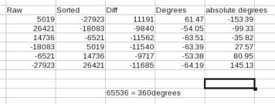
Below is the values from one run without averaging on my golden motor 1000W hub. I have no idea how accuratly they place the hall sensors in the factory.. I guess i will find out once i do some averaging.
hall_sensors1.png
When I looked at the variation of any one sensor it seemed to be about +/- 2.5deg for the worst outliers. most were more consistent.
I will change the code to incorporate some averaging but it is looking promising and for anyone who doesn't trust the software you could specify the hall angle to anything you like :lol:
I need to gather some more raw data to actually see how good it is if averaged.

Now I need to get the PLL running


Edit:
I just tried the PWM at 24KHz and it runs fine but I didn't change ts used to scale the control model to compensate.
anyway I did another capture of the halls while running at 24KHz.Because i didn't change ts the motor was running twice as fast as at 12KHz. It was interesting in that the same sensors as the table above done at 12 KHZ have pretty similar values at 24KHz so the halls are really not exactly on 60deg transitions.
One interesting bit is at 24KHz there is an obvious angle shift of about 10 degrees relative to 12KHz. This could be related to the speed difference, I'm not sure, I'll have to look at that later.
Also out of curiosity I set the PWM up to 40KHz and it ran but I really need to remove some of the overhead in the interrupt as its starting to become tight up there. The control code is pretty efficient but some debugging code is a little boated but remember this is on a general purpose micro (ARM cortex M3) not a DSP! I know I can get 4us back from some earlier tests i did for minimal effort but in reality I don't think it is necessary to run the PWM that high.
 
Fantastic work! I'm jelous of your programming skill.

I'm sure they're not super precise when they install the hall sensors in those motors and some phase error is highly likely. This could cause significant losses if they are off by a few degrees. Synthesizing the hall signals with a PLL might be one way around this.
 
I just finished reading through the progress in this thread. Thanks Ricky for putting so much effort into this and sharing it with the community.

If I am reading this right you are designing this to function with various power stages. Would this controller be able to function with a 300-500V battery and IGBTs? I am not looking at current any higher than the 400A you are specing your sensors too.

Thanks
Kyle
 
Nuts&Volts said:
If I am reading this right you are designing this to function with various power stages. Would this controller be able to function with a 300-500V battery and IGBTs? I am not looking at current any higher than the 400A you are specing your sensors too.
The control board will work with any voltage / current combination since internally it doesn't work in volts and amps but in per unit (percent) so with the right hardware voltage input scaling and current sensors it should work.

The only additional thing for IGBTs would be to arrange a desat input from the gate drive to feed into the shutdown pin of the micro and maybe a separate input to make it stop rather than cycle by cycle limit in that case but that wouldn't be hard. That could save the expensive IGBTs

The only point it knows about real voltages and currents is for user display. Pretty much define 1.0 to be x volts and it works from there. As long as the hardware input scaling allows use of most of the input range of the ADCs its all good.
 
Thanks for the information! I'll sit by patiently watching you're progress and trying to learn enough to build a power stage for one of these bad boy controllers.
 
fechter said:
I'm sure they're not super precise when they install the hall sensors in those motors and some phase error is highly likely. This could cause significant losses if they are off by a few degrees. Synthesizing the hall signals with a PLL might be one way around this.
Makes sense considering they are not that precise in other aspects of the motors. I guess even a mm error is significant in terms of electrical rotation on a hub motor.

I'm hoping to use the PLL to provide angle reference for the vector control as an option but a similar technique could be used on simpler controllers. I'm not sure how the guys with the timing adjuster project handled it.

I've got a bit more debugging to do as my PLL seems to be locking on at the wrong frequency :eek:.
 
Ricky_nz said:
fechter said:
I'm sure they're not super precise when they install the hall sensors in those motors and some phase error is highly likely. This could cause significant losses if they are off by a few degrees. Synthesizing the hall signals with a PLL might be one way around this.
Makes sense considering they are not that precise in other aspects of the motors. I guess even a mm error is significant in terms of electrical rotation on a hub motor.

I'm hoping to use the PLL to provide angle reference for the vector control as an option but a similar technique could be used on simpler controllers. I'm not sure how the guys with the timing adjuster project handled it.

I've got a bit more debugging to do as my PLL seems to be locking on at the wrong frequency :eek:.

I don't use a PLL as it takes too long to get lock. Plus a reliable lock detector is difficult.
Like you I also sample the halls to find their relationship. Then the way I use this information:

- when a hall flips the absolute phase position (I call this phi_hall) is know. At the same moment a timer is reset to 0
- when the next hall flips again the absolute phi_hall is known. The timer count is stored and reset to 0. The stored
timer count gives information about how long it took to get to this next hall. From the calibration the algorithm
knows the 'distance' in degrees between the hall signals (1/6 of a period is optimum but it varies). This can be used to calculate
the timer count for a full period (6 times the last count). I call this TCFP (timer count full period). Notice that the
TCFP is updated 6 times a period, after every hall edge.
- At any moment the phase phi can be calculated using
phi = phi_hall + timer_count / TCFP, both phi and phi_hall have a range 0 to 1 for 0 to 360 degrees.
- Wildly varying TCFP can be used to detect problems as this shouldn't happen.

I like this better than a PLL as at each of the 6 hall edges the phi is dead on. Also the response to speed up/slow down
is practically instantaneous (when the next hall edge comes). You don't need a lock detector to decide whether the PLL is
in lock and whether it's output makes sense.

The only place in my design where I use this phase algorithm is for back-emf sampling during calibration. The ADC's are triggered and the phi
is determined. When the ADC's are done their values are assigned to a bin based on phi (128 bins in 1 e-rotation). After every hall
TCFP is updated. A difference with the previous TCFP of more than 6% and the back-emf measurement is aborted, an
error is reported to the user (excessive slow down of the motor, not good).

Since it cannot be guaranteed all bins will be filled a cross correlation algorithm is used to extract the fundamental, 3, 5, 7 and
9th harmonic, this is the info that will be stored about the back-emf. The phase info from the fundamental can be used to link
the back-emf phase with the phi from the halls. But that's another topic all together :D
 
Happy now year everyone.
Lebowski said:
I don't use a PLL as it takes too long to get lock. Plus a reliable lock detector is difficult.
Thanks Lebowski,
After recovering from the new years drinks :lol: it makes a lot of sense.
Its probably only a small change to my current code too, I hadn't got back to debugging the PLL.
I currently use an integrator and a PI loop as a PLL so removing the PI loop and using just the previous timing information should work.
My code already has the measured angle between halls and the estimated angle from the integrator (I guess acts in a similar manor to your counter).
I read the hall inputs every PWM period and when they change (60deg) I was updating the PLL but it was getting messy as the PI loop for the PLL really needed a constant sample frequency but was only updated when the halls changed and as you say was slow.
I do wonder if the discontinuity between estimated and real will mess my vector control up but when it jumps between estimated and real every 60deg. I guess it will only be a tiny error in most cases. I guess the best thing to do is to go and implement it :).
Lebowski said:
I like this better than a PLL as at each of the 6 hall edges the phi is dead on. Also the response to speed up/slow down
is practically instantaneous (when the next hall edge comes). You don't need a lock detector to decide whether the PLL is
in lock and whether it's output makes sense.
Yep using the 6 edges is good and the PLL would have never been accurate at even those points unless running at a very constant speed which is not really reality, especially on a bumpy offroad situation.
Lebowski said:
The only place in my design where I use this phase algorithm is for back-emf sampling during calibration. The ADC's are triggered and the phi
is determined. When the ADC's are done their values are assigned to a bin based on phi (128 bins in 1 e-rotation). After every hall
TCFP is updated. A difference with the previous TCFP of more than 6% and the back-emf measurement is aborted, an
error is reported to the user (excessive slow down of the motor, not good).
Being vector control mine needs an angle all the time a probably higher accuracy.
I'm planning to have halls and position sensors as optional sources mainly for start up and then run sensorless although sensorless from stopped is the final goal.
It will be good to see how our two designs perform in the real world with their different trade offs etc..

I just need to do a bit more work on the matlab simulation (lunch times at work) and the I'll get the main sensor less part running then I might start with the juicy part of sensor less start up.

I do want some form of sensors available when I test those parts for comparison hence my rush to get sensors usable.
 
Lebowski said:
Ricky_nz said:
although sensorless from stopped is the final goal.
like this :D ?

http://endless-sphere.com/forums/viewtopic.php?f=30&t=34231&p=510965#p510947
Now you need to show that with hi power under heavy load
 
Vector control works now I have an angle derived from the hall sensors :D. I may want to play with the PI gains though.

Well the torque goes way up when you have an angle reference as expected.
Current control without an angle reference doesn't have much torque because as soon as you load the motor the motor loses sync.

Pity it started backwards and the bike fell over causing the pedals to try and eat a hole in the wall while the tyre did a nice burnout on a cupboard door :lol:
Luckily the rubber mark cleaned off the wood veneered door ok and the painted wallpaper that got munched is due to be replaced anyway.
I have just tied the chain off the rear sprocket so the pedals can't move again and i have sat a big SLA on the handle bars to stop it jumping around!

I am now using the timing information from the previous hall period (60deg) as per Lebowski's method and it seems to be giving good frequency and angle information.

I adapted the design to an integrator code block I already had for the PLL but just used it for the synthetic angle between halls, resetting it to the real angle every time a hall sensor changed.
This might create small jumps forward and back in angle but around the hall points but this is expected to be small.

I need to put a speed limit because at high torque settings at light load result in running out of volts and then something seems to be overflowing or going uncontrolled because the wheel reverses QUICKLY :eek:.

I can only test torque control at low power without a load but it does work. -ve torque provides great breaking action where as a change from high to low torque demand in the same direction slows down slowly so it seems to be working.
 
Ricky, try to get real-time phase info out via the RS232 (or whatever communication you've got set up).
The plot in this post

http://endless-sphere.com/forums/viewtopic.php?f=2&t=30851&start=285#p483312

Shows the phase info I collected using the method I described to you earlier.
You can see the 6-staircase at the beginning of the plot, at this point the TCFP
is not reliable enough yet (more than 6% steps after each hall edge in this variable)
so I only use the absolute hall position info. Once the TCFP variances are less
than 6% it declares 'lock' and it uses the timer info to interpolate. Then you get
the staircases as in the second half of the plot. If you look really good you can see
the small steps in the staircase where the halls trigger....

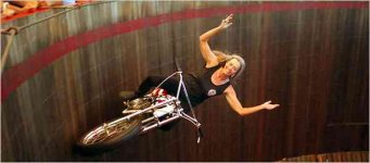
Since Ricky's bike got a taste of it now, for our first e-bike motor sports event
where there'll be drag races and hill climbs I'd like to propose Ricky to star in the
wall-of-death :mrgreen:

samantha_600sturgis.jpg
 
Well today I didn't make too much progress on the motor controller.
I decided it was finally time to sort out the hard drive on my development pc and to upgrade it from fedora 12 linux to fedora 16 by complete reinstall.

Apart from a few issues with the open source nvidia driver messing up display with my older nvidia card during the install and fedora 16s strong dislike for booting raid 1 partitions its back up :D.
I still haven't set everything up yet but I did have to tweak my controller code scraper script and a couple of lines of code in my config app to get them working with the latest ruby and other system tools.

I have been using kdevelop as an editor for my development and because redhat finaly switched to kdevelop 4 I was worried it would not work with my projects that are automake based as they switched over to cmake but it seemed to cope fine as an external makefile project so I can build both again :D.

I did have to track down a couple of perl dependancies etc and the codesourcery toolchain for arm needed some 32 bit compatible libraries installed but if i remember right i needed them last time too.

It took me ages to copy off and sort some of the files on the hard disks but worth it as important stuff is multiple backed up and sorting out the drive is a good thing for when I build a new machine later in the year.

I even managed to wipe only the intended partitions and leave some wanted ones intact.

The machine feels a bit faster. I guess a clean format of ext 4 that hasn't got a couple of years of fragmentation and is not sitting at 95% full was what helped there :lol:


I did have a small play with the motor controller.
A couple of times I mistyped the desired referance current and i have been running 0.005 - 0.014 any more overcomes all friction and the motor ramps up quickly to full speed where it starts banging and is mightly upsert due to running out of volts.

I'm only running on 24 V at the moment to keep the speed reasonable for testng although I have had the controller up to 57V on the RC motor.
For a sense of scale 1 for the referance is currently mapped to 200A phase current. Can't do It because its only 200A DCCTs but I will deal to that and push it up.

I am thinking about a nice way to put a speed component in combination with the torque so unloaded the speed won't run away but that wheel sure accelerates fast if you give it some real amps unloaded :lol:.

I also discovered that some of the sudden torque changes managed to losen one of the axel nuts on the hub to the point the derailer hanger fell off :lol: It dosn't have a torqe arm but the torque washers had been fine upto 1KW stock controllers. The nut on the non drive side is fine. The dropouts even seem ok.

I have been doing +ve and -ve torque and I never did regen on the bike so i guess that might have helpedlosen the nut.

Setting it to 0 torque is quite neat because from speed the wheel coasts for a while yet throw in a bit of negative torque and you can stop it quite quickly. I have got to make sure that part of the code is handed well for real world situations to avoid supprises.

I might have to buy a new seat for the hub motor bike (old one was borrowed to replace a seat on my main bike that fell apart) and a plastic box for the controller soon just to abuse the power electronics in real life situations while I get the sensorless working.

I guess I better get the magura throttle wired up and finally use the bit of code I wrote months ago but have so far not tested to handle the scaling and high pedal lockout etc.

I'm rapidly running out of hollidays but I better get the low level CAN interface configured while I have a can->usb adaptor around to test it against. Once it works I can use my board for the purpose.


Edit:
I have just put code built with the latest arm version of gcc from code sourcery into the board.
It basically works but there is something funny. In open loop it needs a higher current referance to get the motor turning :?.
The code size shrunk slightly and the execution time is slightly faster for the control loop whichis good if it works.
I guess I'll have to go back and retest a couple of the basic building blocks in the code to check nothing got broken.
Sometimes c++ compiler optomiser improvments can expose minor flaws in the code that only show up when the optomiser starts using some language rule that wsen't used before.

On the plus side the configuration tool builds and runs correctly on Fedora 16. One of these days I will try and build it for windows as it is based on QT so should port over easilly.
 
The CAN interface is alive...
[youtube]f2qo8OwWVbM[/youtube]

Well transmit anyway and most likley recieve as the same tracks and interface chip are used.

So far I only initialised it and used a simple polling based send to check the hardware works and the micro is configured correctly.
This is running at 1Mbps, I am sending 1 frame with 8 data bytes every millisecond.
Next up I will try and setup interrupt based recieve.

Appologies for the reflections. Why on earth did they have to start putting glossy screens on all cheap laptops? usless outdoors, bastard to keep clean...
 
Well I nearly got fully interrupt driven CAN running last night. Transmit and recieve was working through some FreeRTOS queues from another task but I had one issue if I caused an error on the CAN bus the micro would lock up in hard fault. I have even got a system in place to handle high priority messages.

With fresh eyes today I just discovered I was waiting for 9 ticks when trying to sccess a queue and this was causing things to back up under fault conditions which caused stack overflows due to the priority of the tasks/intyerrupts involved.
It seems a lot better now that I replaced the '9' with '0' as it should hae been (0 = dpn't wait), That one was definitly a typo :oops:.

All my CAN error counters are working and readable from my config app. It only takes seconds to expose new variables and parameters to the outside world, that earlier infrastructure work I did sure makes things easy now :D.

I did a few tests and this thing can easially use all available CAN bus bandwidth, back to back frames at 1Mbps :).
I have given the CAN interface a reasonable thrashing today and it seems good. at some point I will setup two boards and have them throw frames at each other at high spoeed though.

I probably need to start thinking about the protocol. I want to run over the CAN interface but I will want to keep it simple.
I want to knock up a simple display board using one of my contol boards and a good size backlit alphanumeric display and a couple of push button switches to communicate with the controller over CAN to display some stats live which would be very handy during testing.
 
Now you're cooking :wink:

Imagine a controller you can program like a CA or iCharger without needing a computer. In fact, since the controller needs to have current sensors anyway, why not have it keep track of Ahrs to have an accurate 'fuel' gauge and other functions found on a CA.

Remote display/buttons can mount on the bars. Field programmable current limits, throttle response, etc. would be the ultimate.

OK, let's just make it run a motor first...
 
hillzofvalp said:
who employs you? Are you free lance? how do you have time for this! kids? yes? how?
I do have a 40h/week job in the power electronics industry (MVA level stuff) writing software. (won't say which company online)
No kids so get to play with my hobbies :lol:
Just had the last two weeks off work so extra progress has been made and I had been wanting to get back into it after finishing my kitchen. Its been really good getting back into this project.
I still run out of time. Sleep is a necessary inconveniance :(
 
fechter said:
Now you're cooking :wink:

Imagine a controller you can program like a CA or iCharger without needing a computer. In fact, since the controller needs to have current sensors anyway, why not have it keep track of Ahrs to have an accurate 'fuel' gauge and other functions found on a CA.

Remote display/buttons can mount on the bars. Field programmable current limits, throttle response, etc. would be the ultimate.

OK, let's just make it run a motor first...
Yep making the motor run is most important :lol: ,
I'll get a basic display to display live data but adding features like full configuration from a control would pretty easy. Just need some code to translate my xml files into a set of menus on a display like a cut down version of what I do on my PC already, Just restricted for display limitations etc.
I had thought of communicating with a BMS etc for cell info over CAN if I find a BMS with CAN or if someone designes one etc.

Current used is interesting in that my controller dosen't have a CT on the battery but the battery current should be able to be calculated from the phase currents but there is a couple of spare ADCs that could be easially used.

I do keep thinking of things to add but I do need to focus on the motor first.
 
I have had another good run.

I have split my main state machine so its easier to write tests that can be used for calibration etc and to separate out the normal operating mode. I still need to write the normal mode code state machine but now I have split things up its as easy as filling in one c++ class to complete the missing virtual functions :). This also makes it easier to write alternative state machines for special applications.

I think I solved the change of performance between compilers. I believe it wasen't the compiler but the old change two things at once. I had fixed an execution order bug for the angle but in fixing that I put the current controller outputs one pwm cycle late which is never a good thing.

I have made a short video of the vector control running off the hall angles. I am still commanding the control code directly and don't have the limits for max motor V / battery voltage etc so at one point when the motor goes too fast it suddently thunks as the current controllers lose the ability to control the current in the motor :lol: That is why I now have a piece of wood tied to the bike to keep it off the wall and a 55Ah SLA sitting on the handle bars :lol:

The currents I'm using are way down because the only load on the motor is the inertia of the wheel and a small amount of trag in the motor/bearing etc.

The colour in the video is off. it was really dark so I fixed it in kden live but didn't want to spend time fixing the colour properly. The walls are a discusting pale yellow.
[youtube]Q4xxxkr2kTY[/youtube]

Anyway I'm going to get a few hours sleep. Its 5:30am here and I forgot to go to bed :lol:. I work well on these things at night but I can only do that while I'm on holiday. I never seem to look at the clock in the corner of the screen :lol:.
 
Lebowski said:
are you using 15 to 20 kHz PWM ? I think I can hear it in de video :( :D
Actually only running at 12KHz but most the background noise is from my 2KVA UPS and PCs behind the camera. Also probably some 12KHz is finding its way back into my audio amp through the PC :lol:
I was just avoiding changing too much at once but I definitly know I can go up to 40KHz or more and are planning to go above the audiable range to keep it well inauadable but also because I want more sample points at output frequencies arround 1KHz etc.

Using 12KHz is also probably also giving my more error in hall sensor positions as well so going higher in frequency will help that as well.

Just listened to it again and its also probably partly due to the camara sensitivity I think as it definitly dosent sound that bad in the room.

I have done the change of PWM frequency at run time change to the code and I believe everything that needs to be updated and did a couple of runs at various frequencies.
8KHz is most noticable as expected with a little bit at 12KHz where as 16KHz and 24KHz are better as above the hearing range.
There was still some variation in performance between frequiencies so I will double check I got everything updated correctly in my sample time update code.
 
Back
Top