Rickys High Power Flexable motor controller

RWP said:
Hi Ricky,

Been following your thread with great interest. Thank you for your pioneering work.
I would like one or two of the boards when they are ready. While a relatively good solderer I am not so interested in soldering surface mount components to the board. Hoping one option would be a board with all the surface mounted parts attached.

Cheers,
Roy
Hi Roy,
I can only manage to hand solder a few boards at a time although the last two I buuilt at the same time as it was much quicker as I only had to find each part once but once I get out of the software and hardware development phase
I will have to look at the toaster oven methods of soldering boards with solder paste etc unless I find someone else who is keen to assemble a batch.
I will just have to see how things go. I would think at least organising some way to assembly the control boards quickly would be a good start as the power electronics board has much less surface mount parts and is really easy to assemble apart from lots of heat being required.
liveforphysics said:
You are awesome Ricky! So many folks are patiently and excitedly waiting on every new update of your awesome project. :)
Thanks, Im hoping I don't disappoint :lol:.
So far it seems to be going ok and I'm learning a lot about motor control with 3 phase etc.

Other news:
I have finally solved a problem where on half the power ups the board/software would go so far and hang but if you touched it it might start and run. I found the problem trying to probe the ADC clock input and the scope probe touching a locked up board started it. a few more power cycles and I discovered in the locked up state there was no clock to the ADC. The 8MHz clock for the ADC comes from the micro clock out and I had ended up with a race condition where some times a PWM interrupt would occur before the ADC had clock and there is a busy loop in the interrupt checking that the ADC has finished the conversion and with no clock it was never not busy hence the lockup. The fix move the clock output enable from the wrong place ( from early testing) to inside the ADC initialise routine well before the PWM interrupt is enabled and then all is well. Every boot is a good one now.
I was worried I had an issue with the 3V micro and 5V ADC or something related to that but I had checked the thresholds and they are all good.

I have now fitted the voltage divider to measure the DC bus voltage and calibrated the ADC input. I added a new commend to the command line STatus which prints out interesting values in human readable form. I converted the measured voltage from 'per unit' back to Volts using the base voltage. There is some thing satisfying about having a real voltage printed out on the command line although previously seeing 0.36 was ok but to see 14.4V is much better. I have added the code to display the phase currents in this same command and as soon as I implement the first order filter for the RMS I should be able to print RMS currents on the command line.

I have started on the proper protection code and have added under / over voltage protection based on the measured bus voltage using the ADC at the PWM rate. I will add the hardware voltage trip soon. I have a small issue with resetting the control code after a trip but I have a solution and just need to implement it.

I will also add a software current trip so I can set a current limit much lower than the hardware one which will be useful for the next set of tests I want to do which are full voltage at low current.

I did a test earlier today where I ran it at 70A RMS / phase for a couple of minutes. This was mainly reactive current as I have no way to load the motor yet. I did detect some heating in the main electros so I think I will go ahead and fit the film capacitors in addition to the 1uf ceramic SMD caps in the free locations on the PCB. I have a couple of possible values and types to consider. The heating could also be because my power supply running it is being stressed (possible sagging) and is connected via about 1 meter of cable.
Since the target current per phase for the 80-100 180 is 85A RMS/phase its looking good.
I should be able to push more than 85A/phase once I get things finalised and actually run it off LIPO but that doesn't happen until all protections are in place.

I also are finding the nickel plated brass bolts I am using to attach the outputs to the PCB are getting quite warm/hot.
I probably need to tighten them to the board a bit more when I next unbolt everything from the heatsink. Maybe even solder them to the PCB. I guess I could just not use bolts and just solder output wires into the hole in the PCB but bolts and lugs are more convenient for prototyping etc. I guess unless I can find copper bolts (do they exist?) these are probably the best I can do and some of it may be that they are just not tightened enough.
I have the bolt go through the PCB and have one nut on top and then the lug and a second nut. I suspect I would get lower resistance by sitting the lug directly against the pcb and just using one nut above it so the lug itself contacts the PCB rather than having to go through the brass nut. The PCB is not likely tu be crushed as the hole is surrounded in vias that are all filled with solder.

Still no hardware failures so far :D but a full/near full voltage test is on the horizon, 75V version, I will probably take it up to 57V to begin with ( have a handy 57.4V stack of 150W meanwells) and if all is well push towards 70 with another supply in series.

Once I have done the full voltage low current test in addition to a low voltage full current test I will know that the power electronics are capable of the full current/voltage which isn't easy to test on the bench.


Bad bearing:
I am almost certain now that my first motor has a bad bearing. Scraping noises / squeeky noises etc depending on RPM setting. also run at low current at reasonable speed the motor heats up around the skirt bearing. Hopefully these aren't too hard to replace. I will probably leave it as it is for now as It shouldn't cause problems in my test stand apart from a bit of load and heating. hopefully my 1 year newer motor doesn't have the problem as thats the one I intend to fit to a bike first.
 
Time to be :twisted:, Friday night with light rain so my computer room is cool tonight.

I cranked the input supply up to 57.4V on the DC Bus :twisted:.
I started pushing up the current (Reactive) in the motor :twisted:.

95A_RMS_100_3080.jpeg
Thats above the 85A RMS/phase at rated power of the motor. :D
Remember this is RMS current not peak 95A RMS -> 134A/phase peak.
Running on 57.4V the electros run cooler so I suspect the warmth was partly caused by excessive ripple of the incoming power supply at 15V and 50A/phase.

I have also been looking at what caps to use in addition to the SMD 1uF caps across each FET part. I have got some 1uF leaded caps across two of the FETS in parallel with the SMD ones for a comparison to another phase. I only have a 10mm lead spacing for these caps so the choice is limited. I can squeeze in 15mm lead spacing caps it they are not too much wider than the lead spacing if need be with a bit of lead bending.

I really need to sit down and do some gate drive and bus measurements at the higher bus voltages but I got carried away :lol:

I also need to remove the board from the heatsink (12 MOSFET screws + some board mounting screws Groan) so I can fit a few more parts to make the throttle input active etc. I do need to tighten the bolt on B phase as it is making poor contact with the board and is heating more than the other two to removing the board from the heatsink will serve several purposes.

I have discovered a small bug in my power/IO board implementation. There is a small error on the throttle and brake inputs I pulled them up to 5V but they are hooked to the 3.3V ADC inputs of the micro. I need to change things so that the throttle output is scaled to 0 - 3.3V. The throttle power output is +5V.
I'm not sure if the throttle (hall effect) output would be correct pulled the output up to 3.3V so I may need to keep it at 5V and introduce a voltage divider. This can be done externally to the board if required in line with the throttle so the PCB is still usable.
I'm thinking about hall effect throttles but I also want to support 5K pot throttles.

I have also now got some 1.27mm pitch 10pin IDC plugs so I can make a tidier adapter for my JTAG debugger rather than that tangle of blue wires attached to a PCB mount connector that is way to fragile.
Ricky
 
I love reading your updates, looks like your hardware is ready to go!!

Any progress on figuring out the sensorless startup and running? Here's an interesting application note for sensorless startup by measuring stator inductance. Should work at zero speed full torque. Not sure how this would work combined with FOC...but at least it will get the motor turning :)

http://www.infineon.com/dgdl/ap0801810_Sensorless_Variable_Inductance_Sensing.pdf?folderId=db3a304412b407950112b40c497b0af6&fileId=db3a304412b407950112b40c7c150b39
 
CNCAddict said:
I love reading your updates, looks like your hardware is ready to go!!

Any progress on figuring out the sensorless startup and running? Here's an interesting application note for sensorless startup by measuring stator inductance. Should work at zero speed full torque. Not sure how this would work combined with FOC...but at least it will get the motor turning :)

http://www.infineon.com/dgdl/ap0801810_Sensorless_Variable_Inductance_Sensing.pdf?folderId=db3a304412b407950112b40c497b0af6&fileId=db3a304412b407950112b40c7c150b39


This is called flux-vector control, and it's exactly what he is doing, and has working successfully.
It's about a zillion times better for an EV application than playing a pre-made starting algorithm into the motor and hoping you get enough rotor motion out of it to sniff some BEMF and get it to run (as a standard RC controller does).
 
Hi Ricky!

Your controller looks very promising. The ARM core is fascinating powerful, I have a dev. board with LPC1768 but no time to play with it for now.

Write me up for one or two of these boards when they'll be ready.
 
zlotvor said:
Hi Ricky!

Your controller looks very promising. The ARM core is fascinating powerful, I have a dev. board with LPC1768 but no time to play with it for now.

Write me up for one or two of these boards when they'll be ready.
Ok.
Yes it is a powerful chip. I have had a few calculations take longer than I would expect so I need to look at the assembly GCC is generating. Maybe I'm not setting the correct compile and link options or maybe the optimisation isn't that good for cortex m3 on gcc yet. It isn't in-lining some functions I thought it should.
Its still fast enough but I can see it could be faster.

I am also getting more confident in the hardware all the time.

Other news:
As of 10 minutes ago I just got a simulation working (or appears to be pending more checks) for medium and high speed sensor-less operation :D.
I must be learning something :lol:.

This simulation is using an integrator to model the motor and it recovers the rotor angle. Its still a bit noisy because to remove the DC offset of the integrator I used a diffrentiator. Currently its not a discrete time one so it glitches on the steps of the rest of the simulation . I will look at changing that tomorrow but for now its time for a beer.jpg then sleep.
I need to get the simulation working well using discrete time and then I need to make sure the number ranges are able to be confined to allow the use of fixed point maths then I can implement if in code.

The simulation accelerated the motor up till the demanded current cannot push the motor any faster due to the torque and the Kv as I have no speed control loop, just current demand input.

Looking at the simulation the amount of additional code for sensor-less operation in the medium to high speed area will be small.
The simulation isn't perfect in that some of the motor parameters I have approximated/guessed.
I really need to see if I can reverse the motor model and get an approximate flux for the rotor and them work out a per unit representation of it but the thought of doing that makes my brain hurt :lol:.

One interesting thing I was thinking about the other day, the motor inertia is really low as evidenced by my videos of reversing it while running at speed but on the bike the inertia of the motor will be insignificant as it will be swamped by the inertia of the bike so I should really change the inertia values in my simulation to represent those of the bike.
These vehicle applications are really slow compared to the software.
The time for the bike to accelerate / throw the rider off will be measured in seconds or large parts of where as the controller is working in 8.3ns steps and updating the rotor position and current controller calculations every 83.3us.

I may even increase the calculation rate if there is processor to spare which would ensure enough samples per cycle for motors that require more significantly than 1000Hz input frequency.
 
Another 29degC day today. Wish it was a bit cooler though.
Found a few issues with my simulation so I will play with that some more but I have decided today is the day to get the remaining parts of the power board up and running.

I finally undid all the bolts holding this thing to the heatsink and are fitting the remaining parts now.

I will first try and bring up the Vaux converter. This converter should provide +15V for gate drives and accessories. the voltage can be trimmed a bit by the voltage divider values chosen and I think I will lower it slightly to keep the dissipation down on the control board regulators. I figure closer to 13V is probably good as its also good for any accessories :).
Don't worry about accessories causing the gate drive to collapse, the micro will be checking for that and will shut down the PWM before damage can occur.

I have just soldered the converter chip to the board. solder paste on the thermal pad and tacked a couple of pins then hit it with hot air. its now really well stuck to the thermal pad, the copper under the chip is into the 0V batt plane with no thermal relief so getting that one off the board if I kill it would not be fun :lol:. If anyone sees that guy Murphy keep him away from my place tonight!
This was my first time using solder paste for anything.

I had a small error in my throttle interface circuit and I'm just working out the fix. I assume the Honeywell SS496 I saw referenced in another post is representative of the hall effect sensors in Chinese throttles.
I also need to make sure the interface works correctly with 5K pots as I want to use a Magura on my high power bike rather than a flimsy piece of plastic that feels like its going to fall off. The fix should be really simple. The problem is the input to the digital board ADC is 3V3 and for some reason I had a pull up to 5V.
Since It appears as if the linear hall devices don't require pull ups I will probably leave the pull up resistor off the board and then fit an external voltage divider in line with the throttle as a quick look it appears that the track I would need to cut for an on board voltage divider is on a inner layer :(.
If I keep the voltage divider impedance reasonably high it should work correctly with 5K throttle also. The power out on my throttle/brake/IO connector is 5V so that is not a problem.
 
Looks like there are no major circuit blunders with the Vaux converter :D.
Its powered up and regulating at 12.6V which is where the available resistors I had for the divider put it. should be good enough.

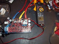
vaux-small2.JPG
I've misplaced the brush off my flux remover so the board isn't very clean yet. Also a few stacked 0805 resistors due to forgetting to order some resistor values.
In the photo the converter is below the row of large holes in the PCB and the -V battery bolt so its quite compact. The image is larger than life. the spacing between the pins on the connector on the left is 2.54mm so that should give you some idea of size.

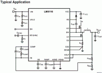
This converter is based on the LM5116 "synchronous buck controller" and if I got everything right it should be good for at least 3A.
Great for running those 12V accessories. The input range should be from 20V - 100V.

I need to order in a couple more values of SMD resistors so that I can put the under voltage lockout in the correct place. Currently its set too low and the converter cannot sustain the set output voltage at such low input volts. This is expected as I didn't have the right resistor and I chose values that would let it work on the low side so I could test at low volts in.
Now its working I will set it up nearer 20V as designed. Note that this voltage is just the low voltage lockout for the converter, when used with my control board the software will shut down the switching well before this point.
It still might be a good idea to setup this hardware UVLO setting based on the desired minimum battery voltage so that the converter doesn't continue to run below the cutoff. This isn't strictly necessary if the micro controls the converter enable.

Now I just need to find a suitable load for the converter to test it at full current.
I need to build a little confidence in this converter across various loads and input voltages before I connect it to the gate drives and controller board. This is especially important due to the failure mode of buck converters :lol:


Assembly of this board is quite easy. Probably a good introduction to soldering SMD parts for beginners. The finest pitch part is the converter IC but you can work up to that by doing the gate drives first.
 
Thanks for the updates!!! Maybe you could put a voltage clamp and fuse on the buck converter in case something bad happens :)
 
CNCAddict said:
Thanks for the updates!!! Maybe you could put a voltage clamp and fuse on the buck converter in case something bad happens :)
Good idea,
I have a 1206 0R resistor connecting the converter to the main battery supply and it would be a good place to put a fuse or fusable resistor of some sort. I guess I need to have a look around and finds a suitable device as it would be a good safety measure. I do wonder though as breaking 100V DC is difficult.
If anyone knows of suitable devices let me know. The current would be at 1.8A max allowing for a minimum input voltage of 20V although typical input voltages will be 50V - 100V range. This can be reduced if a higher minimum input voltage is chosen.

I didn't add any pads for a clamp but I guess the clamp device (Zener maybe) may not need huge ratings as it only has to blow a fuse or fusable resistor. If its small enough a leaded device could be soldered across the output tantalum capacitors. There is a bit of space around them.

I have just tested the current limit.
I had a 12V 50W MR16 halogen bulb so I hooked it up to the output and it lit up (slowly) but not to full brightness. This was intentionally forcing the converter into current limit. It limited at 3A which allowed about 6V on its output once the bulb warmed up a bit :D. It did get the inductor quite warm so I may want to find a more beefy inductor or reduce the current limit slightly. I haven't done any long term tests at current limit yet as I would prefer them to be just at the limit so the output voltage is near nominal.
Although the inductor got warm its not too bad considering its size.


EDIT
Just found some possibly suitable fuses :).
LITTELFUSE 0448002.MR
http://nz.element14.com/littelfuse/0448002-mr/fuse-v-fast-acting-smd-2a/dp/1596928
It is a little too long for the 1206 pads but the track is thick and straight and there is enough room
to just scrape off a bit of solder mask and solder it to the track a one end.
Now I just need to find a clamp device that can open this fuse before failing should the series MOSFET fail on.
 
That fuse looks great!! I think most people have no problem spending a little more money on a controller with failsoft features as opposed to exploding electronics. The voltage clamp is also a great idea to protect inputs from static or other high voltage spikes.

If you want to get really extreme there are some nice integrated circuits that can provide reverse voltage protection for the entire controller. This would take some hefty mosfets on the input but they wouldn't be switching, so losses might not be too bad. The side benefit is that you can use the same fets to stay open when the battery is connected, then turn on after the filtering capacitors are charged. The kontronik PowerJazz does something similar. One thing I really hate is sparking connectors :evil:
 
CNCAddict said:
That fuse looks great!! I think most people have no problem spending a little more money on a controller with failsoft features as opposed to exploding electronics. The voltage clamp is also a great idea to protect inputs from static or other high voltage spikes.
I have found some nice transient suppressors and adding one in parallel with the output caps of the converter will blow the fuse and protect everything else.
All IO lines are protected against over/under/reverse voltage as that was cheep and easy to do

CNCAddict said:
If you want to get really extreme there are some nice integrated circuits that can provide reverse voltage protection for the entire controller. This would take some hefty mosfets on the input but they wouldn't be switching, so losses might not be too bad. The side benefit is that you can use the same fets to stay open when the battery is connected, then turn on after the filtering capacitors are charged. The kontronik PowerJazz does something similar. One thing I really hate is sparking connectors :evil:


My thoughts on reverse polarity protection: (example for the 12 * IRFB4368 board)
Needs at least 2 of the same type of MOSFETS used in the converter and would still dissipate maybe 20W. That becomes about $20NZD in additional MOSFETS and requires space.
The 3 phase controller effectively has 6 pairs of series connected MOSFETS across the supply and their body diodes would conduct on reverse polarity. This design has no shunts to vaporise in the DC path.

From datasheet 1.3V drop each fets diode and 2.6V across a pair it would not take too much inductance / supply resistance to prevent blowing them up provided the input supply is appropriately fused.
The MOSFETS I used are 195A rated each continuous ignoring heating so thats 1170A continuous to blow a fuse.
The FETS are also rated for pulsed drain currents up to 1280A each so 6*1280 = 7680A :shock: should ensure evan the most stubborn fuse blows provided the batteries are low enough impedance. i wonder if it is enough to blow the tabs of the paralleled turnigy nanotechs. It may have a problem with high impedance batteries and too high a fuse rating.

As for sparking at connection I figure that once connected the controller should not need to be disconnected as disconnecting 130+A connections isn't the best setup as connectors can add losses or are bulky.
The controller provides access to the vaux converter enable pin and when disabled the whole think draws <100uA so shouldn't be an issue to leave connected.

If a spark less connection is required then one of the GPIO lines can be connected to a contactor or external MOSFET switch and the Vaux converter powered separately from the DC bus.
The connection to the IO line already comes out as an open collector transistor that can sink 200mA so could easily be setup to drive a relay / contactor etc after the DC bus is sensed to have reached a suitable level via a charge resistor.

It is hard to make very high power setups idiot proof, small and efficient while keeping the cost down.
Accidents will always happen though so minimising damage is a good thing.
Hopefully I have got a reasonable mix.
 
The traditional power supply overvoltage protection is the SCR crowbar. Basically an SCR across the output with a zener diode in the gate circuit. Once the voltage on the gate exceeds the zener voltage, the SCR turns on and shorts out the supply which (hopefully) blows the fuse. Current limited supplies require some attention to the fuse rating if you want it to blow...

Crowbars are crude, simple, and effective. You do have to turn the power off (or blow the fuse) to reset them.

I don't like soldered down fuses. Fuses are meant to be used in circuits where they can be expected to blow. Also, due to their nature, they can and will blow in normal operation. Having to break out the soldering iron to replace them is not good. Also, soldering a fuse can alter its parameters... even for fuses designed to be soldered down.
 
texaspyro said:
Crowbars are crude, simple, and effective. You do have to turn the power off (or blow the fuse) to reset them.
Yes a full crowbar is good. I was looking at clamp type TVS's earlier and your suggestion of crowbar reminded me of Trisils from my telecoms days. These are Transient suppressor diodes that crowbar after a defined voltage is crossed. So I can have a single component that is easy to add to the board that will crowbar rather than clamp which means it is useful for open voltage loop as well as the other condition I wanted to protect against being switching device failing short. ( A clamp would have covered shorted power device but not open voltage loop with functioning converter).
The limitation seems to be the voltages that these devices are available in. I think I could use 2 8V ones in series which would be quite easy to mount on the existing PCB in a robust manor. The next voltage up would be too high.

texaspyro said:
I don't like soldered down fuses. Fuses are meant to be used in circuits where they can be expected to blow. Also, due to their nature, they can and will blow in normal operation. Having to break out the soldering iron to replace them is not good. Also, soldering a fuse can alter its parameters... even for fuses designed to be soldered down.
Fuses failing in normal operation is a valid point but I would think that SMD fuses should be pretty rugged.
If this is a concern it is also possible to run a wire off the point where the fuse attaches and use an external fuse and holder although that adds cost and complexity and more failure points.
If I could get a very small plug in 2A 100VDC rated fuse with a small enough socket I could mount on the board I could consider it for a future PCB but I think this may be another trade off required to keep the physical size under control.
EDIT: just found these http://search.digikey.com/scripts/DkSearch/dksus.dll?Detail&name=F1226CT-ND a bit pricey but can be replaced easily and could probably be fitted onto the existing PCB

The fuse will prevent using the PCB as a fuse which could result is a far worse situation depending on where the plasma goes.
Here is a typical circuit from the data sheet that my converter is based on:
LM5116.GIF
Considering Vin is connected to battery +ve a fuse is useful and anything not on the PCB would be a hassle and its only to protect against internal failure. If an external load is applied to the board it should not be able to blow the fuse because the converter will current limit. I could probably put in a fuse rated at significantly more current than the normal operation to help avoid failures during normal operation since Trisils are pretty robust and their failure mode is to fail short (related to SCRs).

Video of it running without life support, no external logic supply.
[youtube]9mAMxrqC4gg[/youtube]
This is the micro and converter running with a 0Hz output at low current into the motor powered up and running of the battery input terminals, no more need for the separate bench supply for the logic.
 
Tektronix uses picofuses on some of their PCBs. They are about the size of a 1/4W resistor. Their leads plug into pin receptacles that are soldered to the PCB.

A problem that I have seen with soldered down SMT fuses is that the solder process affects the fuse. The heat can be enough to be a significant portion of their opening temperature and it stresses the fuse element. More modern fuses may be better than the ones that I was using.

As far as poly fuses... their ratings/deratings are highly temperature dependent. Maybe not suitable for operation in a controller/outdoor environment. Also the ones that can operate at 100V are rather limited in the available values.
 
If the controller gets hot enough to reduce the current rating of the solid state fuse that might be a good thing.

We used picofuses on some gear and they blew randomly apparently from transients. In the same application the polyfuses have been flawless 24/7 for many years, and if they weren't the whole accelerator would trip off, and we investigate every trip.

Voltage specs are an issue, for any fuse. Many are pretty low. Important to get that right.
 
Another thing to consider in the selection of one-shot fuses is the length of the fuse element. Longer fuses tend to have more problems in high-vibration environments, even though their elements are fatter.
 
Alan B said:
If the controller gets hot enough to reduce the current rating of the solid state fuse that might be a good thing.

We used picofuses on some gear and they blew randomly apparently from transients. In the same application the polyfuses have been flawless 24/7 for many years, and if they weren't the whole accelerator would trip off, and we investigate every trip.

Voltage specs are an issue, for any fuse. Many are pretty low. Important to get that right.

Blowing randomly seems bad :(.
Hopefully there shouldn't be any excessive transients on the vaux converter in normal operation apart from the initial connection to the batteries as there is a 10uF cap on the converter side of the fuse.

I did have a look around for poly fuses and there are a few leaded ones that have voltage and trip current ratings that could be usable but their max fault current is so far from what could occur at 100V that I suspect they may not survive.

texaspyro said:
A problem that I have seen with soldered down SMT fuses is that the solder process affects the fuse. The heat can be enough to be a significant portion of their opening temperature and it stresses the fuse element. More modern fuses may be better than the ones that I was using.
That is a problem. I guess they design them for reflow soldering and don't care about hand soldering. SMD film caps are a bit like that too.


Thinking about fault current rating limits the fuse choice some more
There is not much impedance between the fuse and the main battery pack. Short track off main dc bus of motor controller. There is some resistance in the major failure paths, either through the current sense resistor or through the output inductor but these resistances are rather low.

I was looking at the nano2 fuses and holders but they only have a fault current rating of 50A @ 125V so that rules them out.

The pico fuses have 300A@125VDC interrupt capability which is a bit better.
http://www.littelfuse.com list both axial lead and SMD PICO2 fuses. Unfortunately there doesn't appear to be an SMD socket like the nano ones. I guess a machine pin socket would probably hold the axial ones well enough.

I guess the pico2 is probably the best bet otherwise the fuses start to get physically big quickly although they would have better fault capacity. I guess I just have to try and see if there are any transient issues. Hopefully a 3A fuse is reasonably robust though. It will typically be operating at 2.5A or less.
I'm looking at the 3A device in this datasheet.
http://www.littelfuse.com/data/en/Data_Sheets/Littelfuse_251_253.pdf

I guess buying a few and seeing how they perform in my prototype is probably the best way to see how reliable they are on a bike with all the vibration.
 
Update time:
I've made a bit more progress of the software tonight.
I have got to the point where I need to add parameters regularly and manually adding to tables in the code was a pain
so I decided to do some more work on my configuration tool and spreadsheet parameter table tool.

I have got the perl script that is now generating nice xml files with all the necessary information for my config tool to read from a spreadsheet defining the exposed parameters of the system. I used open office.
The script also creates the necessary cpp and h files for the code.

I have had to make a few tweaks to the config tool code as I added a few xml tags since I originally wrote it.

The only code missing from the config tool for basic parameter editing is the interface code that talks to the board.
I want to get that going shortly as figuring out parameter numbers and changing them on the command line is becoming tedious.
Once I get this going there is some GUI improvments and tweaks but for now I just want basic functionality so I can make more progress on the control code.

View attachment parameters_real1.png


I have also been improving the fault protection code and have added some code (untested as yet) to check for conditions that may damage the capacitors. Its easy to spot so why not prevent the damage.
The list of protections just keeps growing which is all good as long as I avoid false tripping.
 
Awesome, you know you're fine tuning when you're working out the fault protection. It's definately important, but it seems to be an afterthought most of the time. Keep it up!
 
Ricky, you blow my mind every week bro! I have to wipe drool off my face everytime you make an update in this thread.

You ROCK!


-Luke
 
Alan B said:
Just another thought. It is pretty easy to read from Google Spreadsheets. I do that a lot with Python.
OK, I used Openoffice as a while back I found a simple piece of example code written in perl to read it and since perl is good for string manipulation Ii ended up brushing up on my perl.

grindz145 said:
Awesome, you know you're fine tuning when you're working out the fault protection. It's definately important, but it seems to be an afterthought most of the time. Keep it up!
Still some important control code to go but I have been keen from the start to have good protection to ensure that the whole controller is as robust as possible. Its definitely worth getting lots of protection early as it avoids delays caused by cremating your prototypes. I initially had the bare essentials of hardware over current but as I brought up and calibrated ADCs etc I have added the voltage protections.
I have been adding the protections as necessary or when I have sufficient software support to add them.
As soon as I had bus voltage measurement I added a bus over voltage trip which is a good one to have as although my input supply isn't too high relative to the FET ratings (57.4V vs 75V) at this stage some of the things I were doing with the motor caused it to regen and push the bus voltage up which the meanwell power supplys feeding it didn't really like :lol:

Its a bit of a balance between ensuring the system is protected so I don't blow it up and wanting to see things running.
At the start I had to fight the urge to run it too much with minimal protections.
The thing is with power electronics they are not very forgiving if you don't have all the necessary protections or make important checks.
.
liveforphysics said:
Ricky, you blow my mind every week bro! I have to wipe drool off my face everytime you make an update in this thread.

You ROCK!
Thanks for the encouragement :).
Its taking longer than I first thought but thats always the way especially with home projects :lol:.


I've got to do some more work on getting a reliable simulation going in matlab for the sensorless but in parallel with that I'm tidying up protections and general software like parameters etc.
I've got lots of ideas for this controller but its just time.
 
If the sensorless FOC loses sync or has some other problem (phase unplugged, wrong motor values, etc) what will the controller do? Nothing worse than a controller getting confused and then putting 1000A through a spinning motor. It would be nice if after a problem the motor gently coasts to a stop.
 
Back
Top