Rickys High Power Flexable motor controller

CNCAddict said:
WOW, this is really fantastic and fast progress!!! I've personally been waiting for almost a decade for a good "torque control" motor drive and it looks like you're headed in that direction with the 2 phase current sensors.

What do you plan to use as a programming interface; a serial connection with attached PC software? I'm also curious if you are going to open source the software as well as the hardware? Anyhow, I'm in for a few drives myself if everything pans out as planned. FYI there is another gent working on something very similar at scolton.blogspot.com. He has working FOC and about a million pages of info on his blog.

David B.
http://www.xeramotors.com
Hi David,
The programming interface will primarily be USB but the serial port can do most things that USB will be able to do only slower.
Parameters will also be able to be set over the CAN bus.
Currently only the serial port is active. Too much to do so haven't got round to setting up the USB but it shouldn't be too hard when I get round to it.
I have had USB working on an earlier LPC chip so know whats involved.
My configuration app is written in QT and uses libusb so when I get enough working It shouldn't be too hard to get a windows build working.
Most of my development is done in linux :) . The board also has JTAG for programming the micro.

For the software I will probably keep my sensor-less vector control software closed source but may provide a basic framework as open source for those who want to write their own control code. I will think about that a bit more but currently thats the plan at the moment.

I just came in from making a motor mount so I can try and spin up my motor later today.
Just waiting for the paint to dry (won't take long today since its hot although maybe a little humid. I used water based quick dry undercoat).
I didn't really need to paint it but it just covers up the reused wood, I made it out of an old chopped up bathroom cabinet :lol: ).

I have made more progress and now have 3 PWM outputs that look like they are probably at the correct correct on the scope looking at the PWM but I can't tell quickly until I have the motor connected later today although between two or them I connected the inductor and its looking good :).
Its more complicated because I have just added the code to inject a zero sequence waveform onto all 3 phases to all more output volts from the fixed DC bus voltage.

Hopefully I will have more good news in a couple of hours.

Ricky
 
Motor Turning, 4am NZ Christmas day 2010 :D :lol:
3 phase sinewave

I have just got the motor to turn :D.

[youtube]-1HwW0-Jlg8[/youtube]

This is the first time I have seen a Turnigy 80-100 180 spin under its own power in person although I've had this one for nearly a year.
While I'm on the bench supply I am limited in the current and voltage I can throw at it hence the low RPMs
This is using part of the vector control code but its just open loop with no current control.

It uses a DQ to AB block then an AB to UVW block that ffeds the modulator.
An integrator is used to generate a theta (angle) for the DQ to AB block

I can set the integrator gain to set the frequency and the D value to set the output amplitude.
I then trimmed this by adjusting me bench supply feeding the DC bus to bring up to the point where the motor just starts turning.

The really slow run didn't look as jittery in person, I think its an artefact of the camera or compression. The video is showing the correct speed of the motor, yet it can really run that slow!

The open loop nature of this test means the motor is getting much more current than normal for the load and speed as expected so it should get smother when the vector control is fully implemented and the current is controlled..

Next up closing the current loop.
 
Progress looks great. Thanks for all the info on drive programming, etc. USB is perfectly ok for me. Even if you have a linux only version I'll buy a netbook and install linux just to program the drive ;)

Back to the nitty gritty. How are you going to close the commutation loop on your first trials? I expected you would use block commutation and hall sensors, but it seems like you are jumping right into the fancy stuff 8) Are you planning to use hall sensors for rough timing at low speeds and then at higher more consistent speeds use a position estimation between hall state changes? Or did you plan on some fancy sensorless position estimation at high speeds?

I'm also curious about your PWM setup. You are using standard sinewave or SVM to handle the PWM? Oh..and there is some interesting developments on using a single CT to do FOC. It seems a lot more timing critical than using 2 phase CT...but reduces parts count by not needing both a battery current and phase current monitoring (3 sensors total). I also have no clue how robust a solution the single sensor method provides. I got a little lost while reading the following document :)

http://www.microchip.com/stellent/idcplg?IdcService=SS_GET_PAGE&nodeId=1824&appnote=en545803

While searching I also found NXP is doing the same thing...seems like a better document than the microchip one above

http://www.nxp.com/documents/application_note/AN10899.pdf
 
CNCAddict said:
Progress looks great. Thanks for all the info on drive programming, etc. USB is perfectly ok for me. Even if you have a linux only version I'll buy a netbook and install linux just to program the drive ;)
Good excuse to get a net book :lol:
CNCAddict said:
Back to the nitty gritty. How are you going to close the commutation loop on your first trials? I expected you would use block commutation and hall sensors, but it seems like you are jumping right into the fancy stuff 8) Are you planning to use hall sensors for rough timing at low speeds and then at higher more consistent speeds use a position estimation between hall state changes? Or did you plan on some fancy sensorless position estimation at high speeds?
I was going to do halls and block commutation but decided it wasn't too hard to just jump right in to the good stuff :lol:.

First I need to get the current controllers working then I can set a reasonable current request and ramp up the frequency of the integrator used to provide a theta during startup. Once fast enough I will switch over to the common back emf based sensorless mode which will provide sensorless operation at medium to high speeds.
I have yet to decide which sensorless startup mode I will use in the final code. I have some ideas and i will simulate them once I get the medium and high speed parts going.
The reason for a different mode at startup is the back emf falls down into the noise because things like required dead time between the switches causes more error than the back emf we want to measure.

It will likely be possible to add things like use halls for startup and then transition for sensorless at speed etc later but I would prefer to be able to run an unmodified motor without halls if at all possible.
CNCAddict said:
I'm also curious about your PWM setup. You are using standard sinewave or SVM to handle the PWM? Oh..and there is some interesting developments on using a single CT to do FOC. It seems a lot more timing critical than using 2 phase CT...but reduces parts count by not needing both a battery current and phase current monitoring (3 sensors total). I also have no clue how robust a solution the single sensor method provides. I got a little lost while reading the following document :)

http://www.microchip.com/stellent/idcplg?IdcService=SS_GET_PAGE&nodeId=1824&appnote=en545803

While searching I also found NXP is doing the same thing...seems like a better document than the microchip one above

http://www.nxp.com/documents/application_note/AN10899.pdf
Yes im using SVM with the LPC1769's motor control PWM in AC mode. A nice side effect of this is that all MOSFETS are switching all the time so I will not have problems using bootstraped gate drive voltage for the high side FETS.
Yes I had seen the stuff about single CT but decided to makes things less critical by using two. Using just one CT requires more processing time so that is another reason to use two as I would prefer to be able to run motors faster. It should be possible to add things like single CT modes later.
My setup just senses the two phases, I can back calculate the battery current if it is needed so no need for battery current sensing.


A funny thing about the very slow motor tests I did is that at such a low frequency its below the AC mode of my current clamp meter and too fast for DC mode so I just used the scope hooked to one of the CT outputs to make sure I wasen't doing anything nasty to the motor.
 
I think you answered all my questions :) I have a new one though. From what I've seen it's very difficult to do BEMF sensing on sinewave controllers since all phases are switching all the time and the signal is very noisy. Most implementations I've seen use some sort of current sensing and then calculate rotor position using complex transformations. Are you going to get around this by sampling at a high frequency and then reconstructing the BEMF into something that looks coherent? Then I guess the next step would be using motor inductance values to make sure the D and Q currents are at the correct values?

I do agree though that a pure sensorless drive that has "good enough" startup behavior would be awesome. Even if you do add hall sensor/encoder feedback later on for zero rpm torque, it would be great to have a "limp home" mode that is sensorless in case a sensor is damaged.

Ricky_nz said:
Yes im using SVM with the LPC1769's motor control PWM in AC mode. A nice side effect of this is that all MOSFETS are switching all the time so I will not have problems using bootstraped gate drive voltage for the high side FETS.

Another great side effect is synchronous rectification. All but one of the RC escs (kontronik) conduct thru the body diodes during the FET off times and cause all sorts of extra heat in the ESC.
 
CNCAddict said:
I think you answered all my questions :) I have a new one though. From what I've seen it's very difficult to do BEMF sensing on sinewave controllers since all phases are switching all the time and the signal is very noisy. Most implementations I've seen use some sort of current sensing and then calculate rotor position using complex transformations. Are you going to get around this by sampling at a high frequency and then reconstructing the BEMF into something that looks coherent? Then I guess the next step would be using motor inductance values to make sure the D and Q currents are at the correct values?
.
Ahh I didn't explain clearly. I am using the currents to reconstruct the backemf information using a software model of the motor. There is a couple of ways to do this with different calculations /transofmations which is what the other methods are doing. I have some good information from a couple of papers on two main methods of doing it the simple one is a motor model and the more complex one uses a EKNF transformation to do it.

I do not have any measurement of the phase voltages, I can reconstruct them from the modulator input and the measured DC bus voltage. This information combined with the measured currents is used by the model to determine the backemf / rotor position etc.

CNCAddict said:
I do agree though that a pure sensorless drive that has "good enough" startup behavior would be awesome. Even if you do add hall sensor/encoder feedback later on for zero rpm torque, it would be great to have a "limp home" mode that is sensorless in case a sensor is damaged.
.
The other reason for sensorless is perfect motor timing. :) This is important as hall sensor positioning seems to be more critical at high RPMS from what I have read on the posts.

CNCAddict said:
Ricky_nz said:
Yes im using SVM with the LPC1769's motor control PWM in AC mode. A nice side effect of this is that all MOSFETS are switching all the time so I will not have problems using bootstraped gate drive voltage for the high side FETS.

Another great side effect is synchronous rectification. All but one of the RC escs (kontronik) conduct thru the body diodes during the FET off times and cause all sorts of extra heat in the ESC.
Yep. Those body diodes are really inefficient compared to a turned on FET.
On mine I measure 0.4V drop across the body diode which is significantly worse than the 1.85mohms max per FET would cause.
I have 2 FETS in parallel so 0.925 mohm max.
For those reading who like examples the calculations below work out the power dissipated in the MOSFET when it would be off on a simple controller
For example at say 150A
synchronous rectification 150A^2 * 0.000925R = 20.8W
Using body diode 0.4V * 150A = 60W
 
Ricky_nz said:
CNCAddict said:
WOW, this is really fantastic and fast progress!!! I've personally been waiting for almost a decade for a good "torque control" motor drive and it looks like you're headed in that direction with the 2 phase current sensors.

What do you plan to use as a programming interface; a serial connection with attached PC software? I'm also curious if you are going to open source the software as well as the hardware? Anyhow, I'm in for a few drives myself if everything pans out as planned. FYI there is another gent working on something very similar at scolton.blogspot.com. He has working FOC and about a million pages of info on his blog.

David B.
http://www.xeramotors.com
Hi David,
The programming interface will primarily be USB but the serial port can do most things that USB will be able to do only slower.
Parameters will also be able to be set over the CAN bus.
Currently only the serial port is active. Too much to do so haven't got round to setting up the USB but it shouldn't be too hard when I get round to it.
I have had USB working on an earlier LPC chip so know whats involved.
My configuration app is written in QT and uses libusb so when I get enough working It shouldn't be too hard to get a windows build working.
Most of my development is done in linux :) . The board also has JTAG for programming the micro.

For the software I will probably keep my sensor-less vector control software closed source but may provide a basic framework as open source for those who want to write their own control code. I will think about that a bit more but currently thats the plan at the moment.

I just came in from making a motor mount so I can try and spin up my motor later today.
Just waiting for the paint to dry (won't take long today since its hot although maybe a little humid. I used water based quick dry undercoat).
I didn't really need to paint it but it just covers up the reused wood, I made it out of an old chopped up bathroom cabinet :lol: ).

I have made more progress and now have 3 PWM outputs that look like they are probably at the correct correct on the scope looking at the PWM but I can't tell quickly until I have the motor connected later today although between two or them I connected the inductor and its looking good :).
Its more complicated because I have just added the code to inject a zero sequence waveform onto all 3 phases to all more output volts from the fixed DC bus voltage.

Hopefully I will have more good news in a couple of hours.

Ricky


OMG Gorgeous!!! :mrgreen: :mrgreen:
 
Hi All,
i just made my motor run even slower than the first test.
I have got the command line parameter setting working better.
Curiosity got the better of me so I entered the lowest frequency for the integrator giving 0.061Hz :lol: turns over pretty smooth for such a low frequency.

Fixed a bug I introduced in the ADC scaling where I managed to mess up the sign extension handling when converting the 12 bits from the ADC to a 16 bit value. I thought I had it working but had made a small change and broke it :oops:.
When its wrong you got normal looking values then the occasional full scale value!. It wasn't completely broken because if the values were low enough (reduced motor current) then nothing strange happened and negative values came out but once the current go above 20A RMS it started misbehaving. All fixed now. I have tested it over the full range as I need it working well for the next stage.

I have the blocks written to convert the samples currents to 3 phase then AB and finally DQ. I will begin testing those blocks shortly as they will all need to be operating correctly when I try and close the loop with PI controllers in the D and Q.
So I have some more software testing to do now.

I have been doing a lot of work on my motor controller and software late at night and early morning since its cooler.
Too much electronics in my computer room combined with hot days doesn't make the best programming environment.
I should really get an air con unit but too many other things to spend money on at the moment.
 
I've got a few more blocks working on the hardware. The parts needed for processing the measured currents and converting them first to alpha beta and then back to DQ.
Now I have the currents from the motor converted back to DQ I can try and close the current loop with PI controllers.
One for D and one for Q.

The current sensing looks like it is providing valid data to the blocks that follow it.
I tested the blocks independently and chained the main blocks into one chain without the motor and confirmed that what I put in I got out the other end :D.

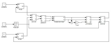
Just thought I would upload a diagram of what I have working so far. An excerpt from my matlab model.
Sorry the image isn't that readable. I need to play around to see if I can get an image from matlab that can be resized to view on the forum but remain readable. The current one had to be resized to view inline and consequently the small text is nearly unreadable now.
impl_1.gif
I have used implementations of a couple of blocks that include more than strictly necessary for motor control such as including zero sequence in the ab representation. The reason is I have other applications for this motor controller in mind :wink:. The extra instructions involved probably amount to <50ns so irrelevant in terms of processing time.[youtube][/youtube]

Edit, a few hours later:
I have just got the PI loops working for D and Q as below.
imp_2.png
Setting the D reference results in a measured D from the motor currents that is very close to the reference and the same for Q referance. The D and Q currents are being controlled independently :D.
With the loops closed the motor current is also now independent of the DC bus voltage.
I have a few more blocks to add that will use the DC bus voltage in the modulator to reduce its impact but they are not needed yet.

I guess I better decide on an implementation for the medium/high speed sensorless part.
I have a couple of options but i'll make a decision after more coffee! then its time for more coding.

Heres a video of me playing with the motor and controller, no vector control yet but D and Q current loops working.
No angle reference from the motor yet, that is next. It reverses pretty quick. one of the bearings in my motor doesn't sound the best although it could be because I don't have the full vector control yet and the PI loops for the current aren't happy.
[youtube]GmOWn8FLcF8[/youtube]
 
At this pace you'll have it making coffee and vacuuming the floor before new years :shock:
 
Ricky_nz said:
Heres a video of me playing with the motor and controller
Impressive video & I'm surprised how "good sounding" the motor makes. :mrgreen: Not real loud & has a "good feel" to it. 8)

Great progress even w/o the AC & at least you have some brewskies to kool down with. :lol:

:twisted:
 
CNCAddict said:
At this pace you'll have it making coffee and vacuuming the floor before new years :shock:
:lol: We shall see, The next part gets interesting. I have done a bit of reading over the last day or so and have decided on a sensorless method to try for the medium and high speed part.
I almost certain I am going to try using a motor model combined with a sliding mode observer for my first attempt at sensorless vector control for the medium and high speed parts.
I am keeping the code quite modular so it would be easy to swap out the observer to a EKNF based one later bit I figure keep things simple for now.

I need to spend a bit of time writing a basic start up state machine to make my tests easier until I implement proper low speed sensorless operation.

deVries said:
Ricky_nz said:
Heres a video of me playing with the motor and controller
Impressive video & I'm surprised how "good sounding" the motor makes. :mrgreen: Not real loud & has a "good feel" to it. 8)

Great progress even w/o the AC & at least you have some brewskies to kool down with. :lol:

:twisted:
Yep I hit the beers after getting the motor running, especially after the second video where i pushed the speed up a bit.
We've got another 29degC day today and I think my computer room gets a few deg hotter.
Time to dig out my fan I think. Its not too bad but lately its been quite humid as well.

Just checked the numbers. I got the motor up to 118Hz in the last video and I should be able to run it up to 1000Hz or more once I move it onto a bigger power supply.
The measured currents aren't quite a perfect sinewave but thats related to the feedback and the lack of a proper angle reference. I may also not have the current control PI loops tuned properly yet.
I am actually pumping more current into the motor than it needs so I guess it might sound even better once I get the sensorless part working, might help with the wave shape also. Without any angle reference the only way to keep the motor synced is to pump more current than necessary in or actually put the V/Hertz mapping in the software but since it was only a test I just gave it plenty of current. It takes quite a bit to stop that motor turning when you have 25A RMS/phase. At these low speeds the inverter is only putting out a couple of volts max and I'm running it from 30V in. I'm limited at the moment to 30V @2.5A in max. I will only move onto a bigger supply after I get a bit more working in the software and gain a little more confidence.

I think one of the bearings in this motor is making a slight scraping sound. Its one of the first batch of these motors with the skirt bearing so maybe there is something not quite right in there as the later version of the motor I have has a few changes. It shouldn't worry me for initial tests but I may have to look at getting a bearing set for it.
 
Hi Ricky,

I'm following your build Topic with great interest. If the controller will remain cost competitive, this could be a big step forward for EV builds! I'm working on a Motorcycle conversion using the Mars ME0913. Would your controller be a good match for this motor?

Ps. I'm hoping you'll make the software open source for everyone to improve. I think you'll be able to make a decent profit just by supporting the board and software if that is what you're looking for. I for one would be happy to buy a ready made controller from you knowing that it's skillfully assembled and the software side is likely to be supported by the community long after you might have moved on to bigger and better things!

KR,
Alex
 
Hi Alex,
atbrandt said:
Hi Ricky,

I'm following your build Topic with great interest. If the controller will remain cost competitive, this could be a big step forward for EV builds! I'm working on a Motorcycle conversion using the Mars ME0913. Would your controller be a good match for this motor?
I suspect It would be capable of driving this motor well with my standard 12 FET power board but I haven't pushed it too hard yet as I'm still improving/writing the software and gaining confidence. I have had it up to 40A RMS/phase and it stays cool.
The 12 FET board might be a little limiting at the peak power range where they mention the motor can handle . "9) Peak current of 420 Amps AC for 1 minute" in their info but It should get close. Each FET is rated for 195A (ie 390A a pair) but at that current they will heat up although for 1 minute it wouldn't heat too much.

Currently the software is sensor-less (although the hardware supports halls and encoders) and that motor has hall sensors which isn't a problem. I am thinking about how to use halls with the sinewave control to aid in start-up performance. They would be optional if I get things working the way I want.
It would also be possible to have some simpler software that uses squarewave but I prefer full vector control using sinewave.
For ultimate performance you could attach an encoder onto that motors shaft and have perfect control from zero.

I'm trying to keep the cost down although because it is more sophisticated than the simpler controllers it has a bit more cost but I think the cost will be worth it for the extra performance / reliability. I'm currently assembling prototype control boards number 2 and 3 and they are the first two with the cost reduction BOM, ie I am not fitting parts that aren't required for use with my power stage board. This is a reasonable cost saving.

So far the controller/software is proving quite robust. I gave it a phase to phase short while running the motor and it kept the current under control, it didn't even get near the hardware current limit :).

atbrandt said:
Ps. I'm hoping you'll make the software open source for everyone to improve. I think you'll be able to make a decent profit just by supporting the board and software if that is what you're looking for. I for one would be happy to buy a ready made controller from you knowing that it's skillfully assembled and the software side is likely to be supported by the community long after you might have moved on to bigger and better things!
KR,
Alex
Still thinking about the open source thing.
I will at least open source the framework software but I need to think a bit more about the control code yet.
I would probably open source the control code also in the event that I lose interest so at least development could continue.


Other news:
I finally got round to moving my subversion server onto a newer machine. It was running on an old 450MHz PII with 120G hard disk that was full! I have now put it on my mythtv back end machine with is a dual core 2.5GHz AMD that recently got upgraded to 5TB of disk with RAID giving a redundant 1TB partition for the SVN and other critical data. I also copy the SVN repo to another machine every night so this means I shouldn't lose any software history due to a disk crash.

I think I need a retirement party for the old PII :lol:. I brought it near the end of 1998 and its been powered up until now, only turned off when moving house etc. Admittedly it started with a 10G hard disk, then went to 45G and then 120G but it has PCI bus throughput issues with 3 ethernet cards and a ATA100 adapters so time to retire it. My mythtv backend box has way more performance than is needed for the TV functionality and having one less PC running 24/7 should help my power bill considering the old PII has a 45W TDP and NO power saving where as the X2 athlon is 65W and power saving that works well :). The other benefit of the upgrade is a server with gigabit ethernet and the ability to use it.

Anyway, back to assembling prototypes, I should have a new control board running tonight without the issues my experimentation of different soldering techniques of the micro caused. The first board had a couple of pads move and an un-fixable short between 2 ADC input pins and has an intermittent connection in the same area so I will retire that board although it may be of some use for non analogue related tests like CAN protocol etc.
The second control board assembled is also the first to have the cost reduced BOM so I'll see how that goes.
Ricky
 
Nice project, Ricky, and great progress!

You might consider moving to one of the new distributed version control systems, many improvements in flexibility and ease of use. You can import your SVN repository so you'll keep all the history, too. And you can have as many backup repositories as you want with a DVCS, and work independently with a laptop, etc when off-net. Changesets are stored in the local repository until pushed into the others. Mercurial is perhaps the cleanest and most popular.
 
Hi Alan,
Alan B said:
Nice project, Ricky, and great progress!

You might consider moving to one of the new distributed version control systems, many improvements in flexibility and ease of use. You can import your SVN repository so you'll keep all the history, too. And you can have as many backup repositories as you want with a DVCS, and work independently with a laptop, etc when off-net. Changesets are stored in the local repository until pushed into the others. Mercurial is perhaps the cleanest and most popular.
They do sound interesting, I should get around to looking at the other version control systems at some point, just been too busy and so using what I know. I have been using CVS and then SVN for 10+ years at home and work so until I get time to have a play I will stick with SVN.
I looked at git when it was first created and at that point is seemed a bit cryptic. I'm sure things are better now.
At least when/if I make the move I won't lose any history.

Other news:
While building up boards #2 and #3 I have finally figured out why I could not get the SD card power switching on board #1 working despite correcting the SO-23 footprint error by creatively mounting the device upside down and rotated ( It sucks when you manage to swap the drain and source of an sot23 MOSFET). I got curious and checked the data sheet of the p channel fet and found the part in the bag labelled IRLML6402 did not match the letter-number code for the FET :oops:. It was for some transistor, no wonder I got confused and just bypassed it. I have another bag of the P FETS and these ones are correct so whether the first bag was messed up by Digikey or myself I will never know :?. I had a definite case of Farnells sending a bag labelled one thing containing another a few years back.
I have built one board with the switch fitted just to see that it works but in reality I have decided as a cost saving measure that the power switching for the sd card is unnecessary since the micro SD card contributes minimal current draw so it is a reasonable saving in parts to just hard wire it on. It will need to be always powered up for data logging anyway. Also not fitting it means the incorrect footprint is a non issue :lol:.

I seem to have misplaced my bag of 20MHz crystals so I may have to fit a different one and change the software to cope but I would really prefer to keep all the boards the same. I guess I can swap it out later. I don't want to delay testing for the sake of a single crystal.

Apart from the crystal and the threshold setting resistors for the hardware current trip boards #2 & #3 are ready to be tested. I will need to order some 10n 0603 caps for a few noise filters but they didn't cause a problem on the first board at the 40ARMS/phase level. I will have to order some as I don't think I can squeeze an 0805 on the pads. My guess is I won't have these for another week due to holidays etc so I'll test without them like I did on the first board and just keep an eye out for noise spikes.

Ricky
 
I have got board #2 up and running :D .
I had to fit a 12 MHz crystal because that was all I had rather than the original value of 20MHz but due to the wonders of modern micros with on chip PLLs all I had to change was one register value and the CPU clock is now back at 120MHZ with a 12MHz external crystal. Much easer than choosing crystals for 8051s with their oddball frequencies to get correct baud rated etc.
I do wonder though if I should switch over to 12MHz crystals or if 20MHz is better :?

The SD card power switching on this board works. It is necessary to mount the PFET rotated 120deg due to the footprint error but that isn't too bad. This is especially true since it is likely that the power switching of the card is unnecessary anyway and can easily be bypassed with one 0R link saving the cost of the FET and associated resistors.

Summary for board #2
1) The sdcard is being read correctly
2) The ADC's all seem to be alive and working correctly (both external and internal ones)
3) The HW overcurrent comparators have the correct referances and are working.
4) PWM outputs make it to the edge of the board.

Due to the better soldering job on the micro and lack of damaged pads this board seems stable without any intermittent faults so far.

A few more tests and I will mate it with the power stage. If all goes well I may consider hooking up to a bigger bench supply and pushing the output current up above the 40A RMS/phase I can get now (at low volts out).

Now I apparently have good ADCs I will add software to detect gate drive supply out of range errors. Another protection feature to help save the MOSFETS.

So overall this board is more functional than the first in that it doesn't have the short between 2 ADC channels or the intermittent connections that #1 had. #1 was a bit of a practice and experimentation board due to my not having soldered fine pitch qfp chips for quite a long time. It also had a few wires tacked on for probes etc during early software development. Hopefully they won't me necessary on #2 and it will be able to be used on a bike in the near future.
As long as I haven't made any mistakes #3 should work also. It has the same BOM as #2 apart from I haven't fitted with sdcard power switch. It really is quicker building more than one board at once :).
 
Any freq xtal should be OK. If you are looking for cheap/common microprocessor crystals then 16 MHz seems to be the most common freq, followed closely by 20 MHz, then (far behind) 12 MHz.
 
texaspyro said:
Any freq xtal should be OK. If you are looking for cheap/common microprocessor crystals then 16 MHz seems to be the most common freq, followed closely by 20 MHz, then (far behind) 12 MHz.
Thanks,
Sounds like I should probably go back to 20MHz when I order more parts then.
I guess I could check to see if 16MHz would work well with the PLL but 20MHz works fine so probably not worth the effort.

Other news:
When getting board #2 up and running I discovered the ADS7862 was not being read properly.
A bit of investigation revealed the CS input sitting at around 2V and not toggling :shock: and the soldering looked ok.
Looking at the code I found rather quickly that

[pre]FIO_SetDir( 4, 0x04000000, 1 ); // P3.26 Output[/pre]
should have been

[pre]FIO_SetDir( 3, 0x04000000, 1 ); // P3.26 Output[/pre]
:roll: Man I hate copy and paste bugs :evil:
got to :lol: though, I got the comment right, just not the important code part.
This left the /ADC_CS pin on the micro defaulted to an input rather than the desired output.
For some reason on board #1 it was low most the time although a few times I had #1 not start-up properly but only when the ADC code was active so possibly related. Being low all the time is a valid condition which is why #1 worked.

I have written a simple test procedure document for testing a new control board to aid in doing and recording important tests of newly assembled boards. It needs a bit more fleshing out although it is up to 7 pages so far. It has proved useful in checking #2 before connecting it to a power stage.

I was fooled on earlier tests of the ADC on #2 as I hadn't hooked up inputs but they all read differently but with the software fix I have started running through my draft test procedure on board #2.
I have reached the following point:
1) power supplies working
2) micro programmed
3) 9 x ADC channels all working correctly and independently and over their full range (6 internal and 4 ADC7862)
4) ADC input voltage clamps ok
5) 6 PWM channels working correctly
6) microSD working
So it looks like I have a good board so far.

I tested the input protection by increasing the voltage on the power supply I was feeding into the ADC input under test to above the maximum. On the inputs with the DA112S clamp chips the voltage getting through to the micro tops out at 4V which is a little high but within range for the micros inputs. I would have liked something lower but the convenience of 3 chips vs 12 SOT-23 devices when hand assembling the board is worth it. The inputs of the micro are held safely within the limiting values.
I did find the that if the input on one ADC channel of the micro gets much above 3.3V all channels read full scale rather than just the affected channel. Not a huge problem as we have still protected the micro from damage.

The ADS7862 inputs are protected by dual diode sot-23 devices and have much tighter clamping limiting the 5V max inputs to 5.27V which is within the maximum input range of the ADC. There are no cross channel effects with the ADS7862 :D.

The ADS 7862 has much tighter limits on input voltage than the micro hence the better clamps.
I suspect the micros ADCs issue is that although 4V is within the limiting values it is above the VDDA so upsets things.

Ricky
 
After confirming that control board #2 was working correctly I decided to push the current up a bit more :twisted:

Doesn't take long to get the 80-100 180 hot with no air flow and the excess power dissipated in the motor :lol: .
The motor is fine but I'm not sure I will run many tests above this level unless I can rig up a computer fan to force air through the motor.
Since the meanwell was maxed out probably over 150W was going in heat somewhere and from what I could tell not too much of it was in the controller so the motor was the target as expected.

[youtube]1N0uguElLag[/youtube]

It was still limited on input power, I gave the 15V 150W meanwall a thrashing until it screamed in pain :lol: and hiccups.
This is made worse because as the controller tries to keep the current at the demanded level the power supply output starts folding back the voltage so the controller sucks more power causing a hiccup situation on a power supply that normally doesn't hiccup.
there was around 2.23V phase to phase and 65A RMS per phase. I did push it to 67A but after about 10s the meanwell gives up.
The next test will have to be on my 3x150W meanwell 57V charger.
There is still a bit more work necessary in the protection part of the software before I connect it to LiPo!

I can command the current through the motor from barely enough to keep it turning right up to as far as the input supply and the FETS will let me :D although its best not to command too much on an unloaded motor as it tends to show as heat!

I'm not sure I trust the phase to phase voltage measurements taken with my old escort DMM but given the speed of the motor they are realistic.

I still haven't got round to working on the sensorless stuff but I have doene a bit more reading so have a clearer picture of where Im going with it. Rebuilding my server the other day took way longer than anticipated taking time away from motor controller development.
 
If you have a good sized input resistor to the ADC inputs (like at least 10K), then then ADC on-chip input clamp diodes will help limit the voltage and cross-channel voltage issues.
 
texaspyro said:
If you have a good sized input resistor to the ADC inputs (like at least 10K), then then ADC on-chip input clamp diodes will help limit the voltage and cross-channel voltage issues.
I'm running 1K at present so could probably increase it although I think part the issue on the micro external clamps is the forward V drop is quite high in the clamp chip. I clamped it back to the 3.3V rail but the signal side gets up to 4V. I don't think these clamp chips use Schottky diodes.
I was keeping it fairly low but there is no reason It couldn't be higher especially on the micro inputs where speed is not an issue.
The easy part is the resistors for the ADC inputs of the micro reside in 2 resistor packs that are only used for protecting inputs to the micro so quick to swap.
 
Hi All,
I've been a bit busy so haven't posted an update for about a week.

This evening I have just finished building another debug tool.
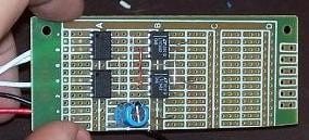
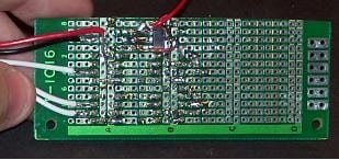
A couple of optocoupers and a couple of SPI DACs so that I can output internal data in a form that is easy to display on the oscilloscope to see whats going on.

DAC-top2.JPG
DAC-bottom.JPG
yes all the Rs and small Cs and voltage regulator are SMD,
I'm running really low on leaded passive parts these days and I have plenty of SMD in the common values as when I buy a new value I buy at least 100 of them.
It uses LTC1452 DACs (cascade-able on SPI) and HCPL-2631 optocouplers.
These DACS may be a little slow but they are leaded (makes prototype board construction easier) and they were available with 2 days of ordering from element14(stupid name), formally known as Farnell shipped from Aussie rather than the typical week wait from digikey.

This should be useful in getting the control code working well as I will be able to look at internal nodes and compare them to plots in the simulation etc.
I added the optocouplers to help try and keep large currents away from my scope which I can't afford to damage.

I just need to write a small driver for the SPI port to write out variables every PWM cycle and I'll be all set.

I am tempted to also buy a USB isolator so I can isolate the hub with the debugger and serial port on so that I can be certain that the high currents don't end up near my PC either although I do need an excuse to upgrade this old AMD 2.2GHz Dual core 939 based board :twisted: The old DDR400 is a little slow these days :lol:

I have been reading up a bit more on sensor less and are still playing around with simulations to confirm my understanding etc. I want to get a reasonable simulation before I convert it to code.

Ricky
 
Hi Ricky,

Been following your thread with great interest. Thank you for your pioneering work.
I would like one or two of the boards when they are ready. While a relatively good solderer I am not so interested in soldering surface mount components to the board. Hoping one option would be a board with all the surface mounted parts attached.

Cheers,
Roy
 
You are awesome Ricky! So many folks are patiently and excitedly waiting on every new update of your awesome project. :)
 
Back
Top