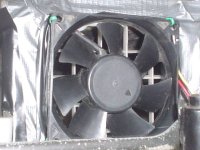
I would never use a fan on a bike like this. It's only adding weight and cooling very little, and consuming more battery.
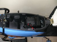
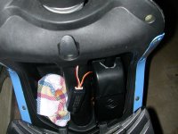
If it was me, I'd look to see if the controller is mounted in a way that you can scoop air from underneath the scooter into the chamber where the controller is (probably under the seat or under the feet compartment).
That way as you drive you'll bring fresh air in without the need for fans. I'd make a small slit into the plastic and bend it in such a way that it scoops air from the front of the bike.
Then I'd create another slit on the back, bending it in such a way that whatever air gets pushed into the chamber by the first slit, will exit by the rear slit.
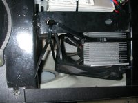
With a natural flow of air the controller will cool lots better than with a fan. Besides a fan is only good in spreading the heat of the controller into the chamber. If the chamber does not have a flow of cool air, or a lot of metal in it connected to the frame, it will heat up, and the fan will become useless in such a case as a fan's performance decreases the hotter the air in a chamber is.
(metal is a good heat conductor, plastic is not).
If it was me, I'd look to see if the controller is mounted in a way that you can scoop air from underneath the scooter into the chamber where the controller is (probably under the seat or under the feet compartment).
That way as you drive you'll bring fresh air in without the need for fans. I'd make a small slit into the plastic and bend it in such a way that it scoops air from the front of the bike.
Then I'd create another slit on the back, bending it in such a way that whatever air gets pushed into the chamber by the first slit, will exit by the rear slit.
With a natural flow of air the controller will cool lots better than with a fan. Besides a fan is only good in spreading the heat of the controller into the chamber. If the chamber does not have a flow of cool air, or a lot of metal in it connected to the frame, it will heat up, and the fan will become useless in such a case as a fan's performance decreases the hotter the air in a chamber is.
(metal is a good heat conductor, plastic is not).