The Road to Higher HP 100-200-500+ HP

Arlo,

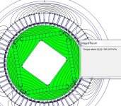
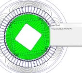
If you look at my rotor model, you'll see that the internal space (ignoring the spokes) is a square orientated at 45 deg. to the magnets. This distributes the iron where it's needed to conduct the flux between the backs of the magnets.
 
OK so I changed the center and torque came up a bit.
Then I tried n40 mags instead of n32 and came up a bit more
Then removed the ovals at the ends of the mags and came up a bit more but the rotor is still getting saturated...
 

Attachments

  • Miles ipm 2.JPG
    Miles ipm 2.JPG
    118.2 KB · Views: 1,607
  • Miles ipm with n40 mags.JPG
    Miles ipm with n40 mags.JPG
    139.1 KB · Views: 1,607
Arlo1 said:
but the rotor is still getting saturated...
You need it to staturate between the poles. The idea is to restrict the amount of iron between the poles (on the airgap side) to the minimum structurably feasible. Otherwise, the flux won't bother to cross the airgap... :)

Are you re-setting the max. scale for flux density to 2T?
 
Miles said:
Arlo1 said:
but the rotor is still getting saturated...
You need it to staturate between the poles. The idea is to restrict the amount of iron between the poles (on the airgap side) to the minimum structurably feasible. Otherwise, the flux won't bother to cross the airgap... :)

Are you re-setting the max. scale for flux density to 2T?
Yes always 2t for now on its always 2t max. I use the snipping tool and its one less step to snip a small picture of the needed data so I don't need to use pix resizer.
 
does this match your idea?
arlo:
Yup that's it.

in the past i have done something similar which is to have a common DC supply feeding two inverters driving two separate motors and this worked really well and i have a patent on how to do breaking without actually needing additional parts for this topology which is cool but not useful for EV as you want regen not dynamic break.

i've never seen this done as you propose, your idea slightly different. same DC source, same two inverters sharing DC source .. and even same driving two separate 3-phase windings like i have done, but in your case the windings are all within ONE motor which is different and so far as i know is unique.

what i was thinking as a topology for EV is same as yours except that the two floating neutrals are the same point electrically connected. i think if they are separated you may have some circulating current issues but i haven't really given it much thought. probably pros and cons to both methods

for now my plan is to use 144Vdc bus because of what miz said on other forumn is that the lower (but not too low) voltage will allow for easier battery configuration. is that too low for you? it would be great if we have a common application and can work together.
 
HighHopes said:
does this match your idea?
arlo:
Yup that's it.

in the past i have done something similar which is to have a common DC supply feeding two inverters driving two separate motors and this worked really well and i have a patent on how to do breaking without actually needing additional parts for this topology which is cool but not useful for EV as you want regen not dynamic break.

i've never seen this done as you propose, your idea slightly different. same DC source, same two inverters sharing DC source .. and even same driving two separate 3-phase windings like i have done, but in your case the windings are all within ONE motor which is different and so far as i know is unique.

what i was thinking as a topology for EV is same as yours except that the two floating neutrals are the same point electrically connected. i think if they are separated you may have some circulating current issues but i haven't really given it much thought. probably pros and cons to both methods

for now my plan is to use 144Vdc bus because of what miz said on other forumn is that the lower (but not too low) voltage will allow for easier battery configuration. is that too low for you? it would be great if we have a common application and can work together.
I was thinking 170v hot off the charger with lipo but.... could be less. that's 148v nominal.... So about the same? I would be using 200v rated mosfets and if I cant run 40s its not the end of the world just would be the max number I would aim for so IN short basicly I think we are on the same page its dangerous enough but not super dangerous. And the battery will only require the BMS and charger to handle 40s
 
a repeat post from another thread, as this is the FEMM thread du jour:


I'm having a look again at detecting the rotor position at standstill, sensorless by measuring the inductance values. I'm busy
with a scheme where I see distinct difference between my AF motor on one side and my big scooter hub motor / little RC motor
on the other side.
The AF motor does not have iron in the inductors (only air), but it does have saturated back-iron behind the magnets. In such
a setup, would you see the inductor values change as a function of rotor position ? The hub/RC do have iron inside, so there
it's no question that the inductor changes as the core saturates, but for the AF ? Would you see saturation of the back-iron ?
Would this be a negligible effect compared to real saturated iron cores ?
 
Lebowski said:
a repeat post from another thread, as this is the FEMM thread du jour:


I'm having a look again at detecting the rotor position at standstill, sensorless by measuring the inductance values. I'm busy
with a scheme where I see distinct difference between my AF motor on one side and my big scooter hub motor / little RC motor
on the other side.
The AF motor does not have iron in the inductors (only air), but it does have saturated back-iron behind the magnets. In such
a setup, would you see the inductor values change as a function of rotor position ? The hub/RC do have iron inside, so there
it's no question that the inductor changes as the core saturates, but for the AF ? Would you see saturation of the back-iron ?
Would this be a negligible effect compared to real saturated iron cores ?
I think Luke and I chatted about this and there is no saturation in ironless core stators. Your limit is purely copper losses.
 
Arlo1 said:
I think Luke and I chatted about this and there is no saturation in ironless core stators. Your limit is purely copper losses.
Isn't Lebowski referring to the rotor back-iron, Arlo?

Lebowski said:
Would you see saturation of the back-iron ?
I've always assumed you wouldn't. It would be nice to test this, though...
 
Miles said:
Arlo1 said:
I think Luke and I chatted about this and there is no saturation in ironless core stators. Your limit is purely copper losses.
Isn't Lebowski referring to the rotor back-iron, Arlo?

Lebowski said:
Would you see saturation of the back-iron ?
I've always assumed you wouldn't. It would be nice to test this, though...

Well I did see some effect still in the AF motor, but it was only a few % compared to what I saw in both
the hub and little 5-wind-on-only-one-tooth RC motor. Maybe it has to do with how the field lines from the
inductor close.. I can imagine in my air core AF most field lines close right around the coil, and only
a few % goes through the back iron. Then you would see an inductor change, but only a small one caused by
the few field lines that take the path through the back iron..

what do you guys think ?
 
the book "axial flux permanent magnet brushless machines", 2004, does not help too much. basically it says for coreless AF machines using high frequency injection method is not to effective because the machine has very low saliency (ideally 0). your application is for a bicycle though isn't it? what's wrong with bEMF method? you peddle first and then let the motor take over?

anyway, for questions like this i find it really helpful to do a google search and put the word "thesis" in there because a lot of really good information which is to the point and quick to understand can be found in this type of document.
 
I was thinking 170v hot off the charger with lipo but.... could be less. that's 148v nominal.... So about the same? I would be using 200v rated mosfets

that would be cutting it pretty close.. join me with 250V mosfets. :)

what do you mean with "and if I cant run 40s its not the end of the world just would be the max number". i don't know your lingo :?
 
HighHopes said:
I was thinking 170v hot off the charger with lipo but.... could be less. that's 148v nominal.... So about the same? I would be using 200v rated mosfets

that would be cutting it pretty close.. join me with 250V mosfets. :)

what do you mean with "and if I cant run 40s its not the end of the world just would be the max number". i don't know your lingo :?
Sorry I did word that funny.
I figure 40s lipo to be a nice number but if Its a problem and 36s lipo is ok then I will stop at 36s lipo!
I will be working this out as I build the motors so I can wind the motor to use what ever voltage I want.
 
ya it's like an iterative process. what power level do you want? i'm trying to avoid using modules because i think it is more interesting/challenge to get an inverter using discretes. let's say we arbitrarily fix the voltage at 144Vdc, then that means full charge of 172V so should use a mosfet rated for 250V. to stay in the discrete package assuming 4 parallel mosfets per switch that means a phase current of ... and thus you have the power level you can achieve. then, two of these in parallel and you have your design's power level. but i don't think it will be 500HP.. i think with this method you would be lucky to get 50HP. but hey, its an iterative process :)
 
Yup hence the thread title ;)
 
HighHopes said:
the book "axial flux permanent magnet brushless machines", 2004, does not help too much. basically it says for coreless AF machines using high frequency injection method is not to effective because the machine has very low saliency (ideally 0). your application is for a bicycle though isn't it? what's wrong with bEMF method? you peddle first and then let the motor take over?.

all in the name of progress dude :D my controller runs sensorless FOC but to 'start' the motor it either needs hall sensors
or it needs a push / free running very low cogging. I see getting rid of the hall sensors as the next step: I want to be
able to start the motor under heavy load, but sensorless... I think I know how to do it, but as mentioned, I saw big
differences between my AF on one side an the more traditional motor on the other side
 
check out this thread and contact the supplier of this motor and controller for you need because it might be useful http://endless-sphere.com/forums/viewtopic.php?f=30&t=50929&p=761180&hilit=liquid+cooling#p761180
 
Back
Top