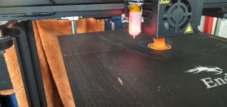
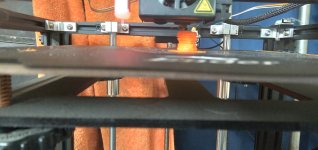
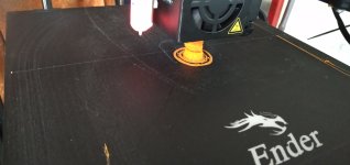
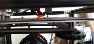
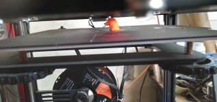
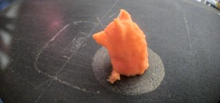
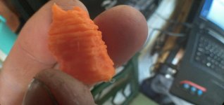
What shall we do with a 3D printer...early in the morning!

I've had issues similar to that where the nozzle blocked....but if that happened it would still be hot.
Yeah, it definitely wasn't blocked; after seeing it was not going to be able to continue the print**** I stopped it and verified the whole head was cold (room temperature), and using the manual feed wheel worked fine, and could be used to push filament out the nozzel once I initiated the preheat PLA menu option.


**** no way I know of to recover back down to the last layer actually printed, though there ought to be one; I can think of some ways to manually modify a model to do it or if I knew how to hand-edit gcode it could be done, but both seem like a PITA and only worth it if the print is likely to have failures more than once along the way....

I've also had similar issues with my PC 'sleeping' even when using Power Toys to prevent. Not sure why, but sometimes the USB connection to the printer seems to corrupt causing jibberish on the printer LCD, but the print continues regardless.

The printer LCD was normal, still sitting at the printing screen for the printer as usual, still displaying the assorted printing info and updating as it continued moving the head....


As for CAD software....call me old-school but I'm a fan of Sketchup Make. Specifically Sketchup Make 2017 which was the last free, standalone version google offered before forcing you to sign in/up to use. It still has a decent following for that reason and many plugins including STL conversion and 3D print 'checking' for holes and other issues.
I'll check it out.

If my ancient version of LW3D (6?) could import and export STL and didn't use a parallel-port Sentinel dongle, I'd probably just use it. But AFAICR the Sentinel software for it wont' run on anything newer than Windows XP, and won't run thru a USB-parallel adapter either, you have to have an actual physical parallel (LPT) port on the motherboard or an ISA (!) card for it to work. So...it'll only run on one working computer I have, and it's not presently installed on there...I should dig it out and install it though, just for times when I just need to *do* something that I know I can just go do.... :)

I forgot that I also still have Truespace2 from the early 90s but I don't think it runs on anything past Win95 or maybe 98. :lol:
 
Wow, ok, guess I'm not as old-school as that!

You can resume prints, and yes it is a bit of a PITA, however if you're printing something that takes 30+ hours it could be worth it. I think that German guy named Thomas something had a video on it a little while back. Involves editing g-code etc. Not something I think I would ever bother with.

Cheers
 
I'll poke around for the video; for me it could be worth it, especially since most things I expect to be making, especially at first, don't need to be perfect, just finished. :)

EDIT: I found this one by CNC Kitchen (haven't watched it yet)
and this instructable (haven't read it yet)
 
Last edited:
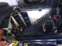
Wanna talk about tricky first layer problems? It took me an hour of tweaking settings to get this mess of a first layer to settle correctly!
IMG_20240119_190539.jpg
 
Looks like what happens if you try printing those vomit-joke toys. ;)

What was it *supposed* to look like?
I'm printing test wind turbine blades. Since the shape is so curved and irregular, there's no flat surface to sit on the bed, so that first layer you're seeing is a massive amount of support structure. It will of course lead to a rough layer on the side that prints onto the supports, and that will need sanding and finishing. But the final blade should turn out well.

I found out that you can pull a CAD for the helicopter blades of the Ingenuity drone on Mars, since NASA publicizes everything they do. So I'm making a small wind turbine based off those blades, mostly for fun
 
Hmmm...I wonder what the turbine will do, based on blades meant to keep something at presumably very high prop RPM aloft in an atmosphere something like half a percent of the density of ours? (assuming I'm remembering right)

My "skeleton bones" have a similar problem, even one bone at a time laid "on the bed" (or bunches in parallel but still flat on the bed); there's no getting around the support structure.

If the blades could be printed vertically, do you think they'd print correctly if the layer density is high enough to "force" the layers together (so they don't come apart when spun)?

After I examined the vertical print I made, I think with the "bones" I am going to have to print them so the layers are along the length to be sure of enough strength to not separate between layers, so with them all parallel to the bed instead of perpendicular to it. I think this is going to use more plastic to make the support structures than otherwise, but the bones should be less likely to "snap" along a layer line.

it might not matter for shorter ones with less stress from end to end, but I am concerned about the longer ones (equivalent to radius/ulna/humerus and tibia/fibula/femur, and probably also the metatarsals/metacarpals which are much longer than the equivalents in a human with different stresses on them). Maybe also the ribs, but those would have to be printed with the "edges" vertical and the curve along the plane of the bed.
 
A quick poke around found this
makes me think I should get it tattooed on my forehead along with a hazmat logo.... Maybe change the wording a bit to "returned sample". :lol:
1705723277540.png
 
Hmmm...I wonder what the turbine will do, based on blades meant to keep something at presumably very high prop RPM aloft in an atmosphere something like half a percent of the density of ours? (assuming I'm remembering right)
You're remembering right. And I don't have to just wonder what it'll do, since we have 3d printers, we can just do it and see for ourselves! I've been playing with small wind turbines for years, and the challenge is always how to get any sort of movement from low wind speeds. My thinking is that NASA designed these airfoils to get a lot done with very little air. Conversely, they should be able to do a decent amount of movement with very little winds speed. I know that's a generalization, and I don't expect to be right. While I will be putting these on a generator and seeing what I can get, ultimately this is going to be more of a garden decoration, which is still cool, if you ask me!

Besides, wind generation is exponentially proportional to swept area. Meaning, any turbine blades that are small enough to print, are never going to be big enough to generate significant energy. That's fine, I like making these as a hobby.
If the blades could be printed vertically, do you think they'd print correctly if the layer density is high enough to "force" the layers together (so they don't come apart when spun)?
This is indeed the issue, and why I'm printing them laying down. It's not so much the spin that will separate later lines, but the force of a gust of wind bending the blade perpendicular to layer lines and snapping them.

The other issue with printing something tall and thin is that the taller it gets, the more it's going to wobble as the bed slides back and forth. It happens less with tall and fat prints, but something thin like a blade is going to have a lot of y-shift.
It's a silly video, but you can see that the round hat they printed turned out fine at 10ft tall, but the vertical, thin sword got real bad layer shift as it got taller. Same thing would happen to my turbine blade, even at a smaller scale, because it's so much thinner than that sword.

So, lots of support material and a rough side that will need to be sanded and smoothed. But we'll see!
 
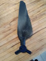
Turned out very interesting!
IMG_20240120_091818.jpg
Like I said, I've been hobby making various small wind turbines for years, just for fun, and I've seen a ton of different airfoil designs, with all their pros and cons. This one is really weird: the leading edge is thin instead of fat and curved, so it seems backwards to me. Very curious to see how it spins.

I think airfoils are a really great use for hobby 3d printers. A perfectly designed and shaped airfoil is something that's really tricky to make by hand with conventional methods. But with printing you can just pull up a free design from online and stretch it into whatever blade shape fits your printer. As an experimental tool for testing out airfoil designs, printing is pretty great.


Tom Stanton had two interesting ways to use 3d printing to make airfoils, effectively.
 
You're remembering right. And I don't have to just wonder what it'll do, since we have 3d printers, we can just do it and see for ourselves!
true...I suppose I was verbalizing the question(?) to generate thoughts about it (such as your idea below) that could then be compared to what actually happens. :)


I've been playing with small wind turbines for years, and the challenge is always how to get any sort of movement from low wind speeds. My thinking is that NASA designed these airfoils to get a lot done with very little air. Conversely, they should be able to do a decent amount of movement with very little winds speed. I know that's a generalization, and I don't expect to be right.
That's a logical conclusion; I wonder if they were designing for specific air pressures to generate the lift, and if the higher air density here would create completely different pressure patterns, and so different results?

I have not looked it up...but did they test fly prototypes of that here in normal air pressure? (or did they just do it in test chambers emulating martian pressures?)

While I will be putting these on a generator and seeing what I can get, ultimately this is going to be more of a garden decoration, which is still cool, if you ask me!
Probably a more useful one than the one I have:
DSC04573.JPG


Meaning, any turbine blades that are small enough to print, are never going to be big enough to generate significant energy.

I suppose that depends on a few things:
--size of the printable area (how big your printer is)
--design of the parts of the blade to assemble into a larger structurally-sound blade
--willingness to deal with all of that ;)


This is indeed the issue, and why I'm printing them laying down. It's not so much the spin that will separate later lines, but the force of a gust of wind bending the blade perpendicular to layer lines and snapping them.
That last is the problem I expect to have with vertically-printed "bones".

The other issue with printing something tall and thin is that the taller it gets, the more it's going to wobble as the bed slides back and forth. It happens less with tall and fat prints, but something thin like a blade is going to have a lot of y-shift.

With a printer that moves only the head and not the bed, that should be less of an issue. I've seen articles on converting a printer like mine (Ender 3) that moves the bed for X, and head for Y and Z, to one with a stationary bed and moves the head for all axes.

Then stiffness of the framework the head moves on is the limiting factor (and the surface the entire device is placed on). There are relatively easy, if space-consuming, methods to stiffen vertical structures (including guy wires, triangulation, etc), so if such a project was actually necessary, it could be done.

Sensor systems could also be implemented to allow the printer to monitor horizontal deflection using IMUs (accelerometers, etc), which are cheap and tiny, so it could compensate for the deflection by moving the head differently to keep it where it should be. The IMUs would necessarily only be monitoring the printer itself, not the print, unless the user were to stick them onto the exterior of the print at specific heights as it reaches those points. (presuming the code has been written to compensate for such movements based on specific heights; since mass of the print would vary and so then would what position change a specific acceleration would crete)


Anyway...while it wouldn't be the simplest thing to do...it could be done. :)
 
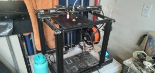
Raining today, so the outside stuff I'd planned to do (trike maintenance mostly) got cancelled, and isntead I poked at the broken Ender5Pro I'd gotten that deal on. I reconnected all the wires, many of which were not plugged in, then turned it on and it powered up; a quick test of preheat for PLA heated up bed and head correctly, and a quick "home" put the head and bed where they should be.
20240121_162458.jpg

The interface is visually VERY primitive compared to the Ender3S1, and it's firmware version is MUCH lower (at least two whole major version numbers plus some point versions). I'm looking into updating the firmware if there's one available for it, but apparently have some reading to do to be sure I get the right one for it (and/or build the right one with the right settings, since that's apparently a thing, too).

20240121_170318.jpg


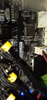
The board in this one is "the silent upgrade", but otherwise unspecified by the original owner. A picture shows it's the Creality v4.2.7 version, which according to the Creality site
should have a newer firmware (4.2.7) than the April 2020 Marlin v1.1.1 that it's info screen shows.
20240121_170217.jpg 20240121_165950.jpg


It uses a microSD intead of the fullsize one the Ender3S1 uses, and I didn't have a quick access to the reader for those to stick a model on it, so I hooked i tup to the laptop I used on teh E3S1 and used Pronterface to print those calibration steps (took several tries to get teh Z axis close enough to even touch the head to the bed correctly to even begin printing).

Then I used Cura to slice that little wolf-head model for the E5P, then used Pronterface to direclty send the model to the pritner and run it.
20240121_173344.jpg

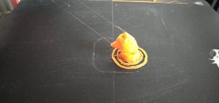
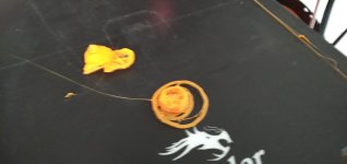
It ran ok, but not too many layers in, a problem began that is probably the "wierd problem" the original owner reported with it (since he didn't really say what it was that I can recall): It started moving the z axis (the bed) down just a hair too far, every few layers. Not *every* layer, but apparently relativley consistent in how many layers apart the "gaps" would be.
20240121_162444.jpg 20240121_162450.jpg 20240121_162905.jpg 20240121_163002.jpg 20240121_163049.jpg

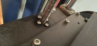
Since the entire control board was replaced with an upgraded one by the original owner to fix it and didn't change the problem at all, this indicates some probably mechanical issue with the z-axis motor, sliders, or jackscrew. Examining this all closely, I found the screws attaching the "nut" to the bed frame were all loose by a significant amount. The pic below shows three tightened down and one still as it had been for comparison.
20240121_163238.jpg

Tightening those changed the problem slightly, but didn't correct it--the layers now adhered to each other a bit (where before they were nearly completely separated), but the gaps are still there.
20240121_173355.jpg20240121_173941.jpg20240121_174544.jpg20240121_174830.jpg20240121_174853.jpg20240121_174904.jpg20240121_174916.jpg20240121_175007.jpg


I don't see any other mechanical issues with the supports, bushings, screws, etc., that could possibly cause such a periodic incremental issue. A motor issue could cause a problem, if a complete rotation of the motor would normally move the bed by about 2mm-ish, as that's about the thickness of the correctly-printed layers, so a motor problem where it rotates extra distance suddenly at the end of a rotation could cause the gap.

So I think I will try a spare stepper motor to see what happens--AFAICR the steppers I got in the "kit"
to experiment with for the Snuggles robotics project are the same as these. That will either work, or not.

If not, I'll swap the Z axis motor for the Bowden-feed motor. Doing that, if the bed moves corectly but the print now gets regular globs in it from uneven feeds, then the motor is the problem.

If the problem still continues, I'll work on testing the wiring harness to the z-axis motor, as that's all that's left that I can think of without further study of the z-axis mechanism.


The schmoo was a bit put out with the whole thing, so she pouted on the porch with the rain dripping off the roof onto her head. :roll:
20240121_154633.jpg
 
Last edited:
So the motors in the kit
are not identical. I couldn't find a spec for them to compare to that of the ones already on the printer, just a bunch of pages that give general info on NEMA 17 motors, some of which list specific models, but none of which give me enough info about either one to know if they both have the same properties and thus would move the same.

The kit motors are only listed on the page as "4401 Stepper Motor". The printer motors are only listed as 42-34 motors. Physically the kit motors are a few mm taller, but the same across the face and the moutning holes and shaft.

Eventually I found some info based on the numbers engraved on the actual motors:
Kit: Usongshine Stepping Motor US-17HS4401S comes up with a few, all seem to be the same so here's the one from the Handson Technology PDF (attached)
.• Nema17 Bipolar
.• Number of Phase: 2
.• Step Angle: 1.8°
.• Phase Voltage: 2.6Vdc
.• Phase Current: 1.7A
.• Resistance/Phase: 1.5Ω ±10%
.• Inductance: 2.8mH ±20% (1KHz)
.• Number of Wire: 4 (100cm Length)
.• Holding Torque: 43Ncm
.• Shaft Diameter: Ø5mm
.• Motor Length: 40mm
.• Rotor Inertia: 54gcm2
.• Temperature rise: 80°C Max
.• Insulation Class: B
.• Dielectric Strength: 500VAC/1-minute
.• Mass: 280g

Ender5Pro Printer: bj42d15-26v19 comes up with no actual datasheets. The closest I found was this
that is for a very different long round stepper motor "series 42D". The info I can find on the Z-axis motor on the E5P is that it should use 1.8 degree steps and .4Nm holding torque, so it should work with the 4401 above, but I just cant' tell for sure from the specs I can find.


So I went ahead and tried it anyway, and from the results (spaghetti in air) can see that the step size for the kit motors is larger by some significant amount than for the ones already on the printer, since it is moving the Z axis down for each layer so far that the next isnt' even printed on the previous. I'm sure there's a way to compensate for this other than editing the values in a motor library and recompiling the printer code, but I didn't run across it quickly, so after lunch I'll swap out the filament feed motor with the original Z-axis motor (also removing the test motor from the Z-axis and putting the filament motor there) and see what happens.
 

Attachments

  • 17HS4401S-Handson.pdf
    134.3 KB · Views: 0
  • L011557 - 42D Series Spec Sheet.pdf
    651.2 KB · Views: 0
true...I suppose I was verbalizing the question(?) to generate thoughts about it (such as your idea below) that could then be compared to what actually happens.
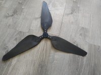
Prime example of why I wanted to just print it and find out: it's spinning backwards. I don't know why. I mean, clearly it's spinning the way it's supposed to be spinning, because it goes 100rpm if you blow on it. But I don't know enough about airfoil design. I sure thought I did, and I drew up all the parts so that it would spin clockwise, but it doesn't.

IMG_20240121_140026.jpg

Looking at just the top blade. I thought the right side was the leading edge, because it's cupped and protruding into the direction of the oncoming wind. But it's the trailing edge. How? If it's trailing, isn't it making drag? Someone with more airfoil experience than mean explain it please!

Anyway, 3d printing is sweet, cuz sometimes you don't know how things work until you hold them in your hands. That's how my brain works anyway.
 
There is a chap in Wales that has a serious homestead theme going, I have to say the man is a bloody genius with wood, he hand carved functional balanced wind blades on his youtoube channel
 
Raining today, so the outside stuff I'd planned to do (trike maintenance mostly) got cancelled, and isntead I poked at the broken Ender5Pro I'd gotten that deal on. I reconnected all the wires, many of which were not plugged in, then turned it on and it powered up; a quick test of preheat for PLA heated up bed and head correctly, and a quick "home" put the head and bed where they should be.
View attachment 346341

The interface is visually VERY primitive compared to the Ender3S1, and it's firmware version is MUCH lower (at least two whole major version numbers plus some point versions). I'm looking into updating the firmware if there's one available for it, but apparently have some reading to do to be sure I get the right one for it (and/or build the right one with the right settings, since that's apparently a thing, too).

View attachment 346348


The board in this one is "the silent upgrade", but otherwise unspecified by the original owner. A picture shows it's the Creality v4.2.7 version, which according to the Creality site
should have a newer firmware (4.2.7) than the April 2020 Marlin v1.1.1 that it's info screen shows.
View attachment 346347 View attachment 346346


It uses a microSD intead of the fullsize one the Ender3S1 uses, and I didn't have a quick access to the reader for those to stick a model on it, so I hooked i tup to the laptop I used on teh E3S1 and used Pronterface to print those calibration steps (took several tries to get teh Z axis close enough to even touch the head to the bed correctly to even begin printing).

Then I used Cura to slice that little wolf-head model for the E5P, then used Pronterface to direclty send the model to the pritner and run it.
View attachment 346349

It ran ok, but not too many layers in, a problem began that is probably the "wierd problem" the original owner reported with it (since he didn't really say what it was that I can recall): It started moving the z axis (the bed) down just a hair too far, every few layers. Not *every* layer, but apparently relativley consistent in how many layers apart the "gaps" would be.
View attachment 346339 View attachment 346340 View attachment 346342 View attachment 346343 View attachment 346344

Since the entire control board was replaced with an upgraded one by the original owner to fix it and didn't change the problem at all, this indicates some probably mechanical issue with the z-axis motor, sliders, or jackscrew. Examining this all closely, I found the screws attaching the "nut" to the bed frame were all loose by a significant amount. The pic below shows three tightened down and one still as it had been for comparison.
View attachment 346345

Tightening those changed the problem slightly, but didn't correct it--the layers now adhered to each other a bit (where before they were nearly completely separated), but the gaps are still there.
View attachment 346350View attachment 346351View attachment 346352View attachment 346353View attachment 346354View attachment 346355View attachment 346356View attachment 346357


I don't see any other mechanical issues with the supports, bushings, screws, etc., that could possibly cause such a periodic incremental issue. A motor issue could cause a problem, if a complete rotation of the motor would normally move the bed by about 2mm-ish, as that's about the thickness of the correctly-printed layers, so a motor problem where it rotates extra distance suddenly at the end of a rotation could cause the gap.

So I think I will try a spare stepper motor to see what happens--AFAICR the steppers I got in the "kit"
to experiment with for the Snuggles robotics project are the same as these. That will either work, or not.

If not, I'll swap the Z axis motor for the Bowden-feed motor. Doing that, if the bed moves corectly but the print now gets regular globs in it from uneven feeds, then the motor is the problem.

If the problem still continues, I'll work on testing the wiring harness to the z-axis motor, as that's all that's left that I can think of without further study of the z-axis mechanism.


The schmoo was a bit put out with the whole thing, so she pouted on the porch with the rain dripping off the roof onto her head. :roll:
View attachment 346338

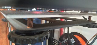
I got rid of the silly springs that hold the printing table. It prints and calibrates better now. In fact it's now set and forget.
 
I have seen well, heard of an issue like this, IIRC it was the actual screw that had gotten slightly worn and was causing slippage....No clue where that memory came from, but from the pics yours looks fine, not that i have any idea of wth I am looking for...
 
I might do something like that eventually for either or both of the Enders, but that "can't" be the cause of the Ender5 problem with printing a few layers, gapping, printing (AFAICT) the same number of layers, gapping the same amount again, and repeating this, probably for the entire Z-axis height. It appears consistent, not random.

The two things that make the most sense to cause this are a software issue in the printer board (which has been replaced with a completely different one) and a mechanical issue in the Z-axis motor itself. Either issue that could cause it to advance extra steps every so many steps would cause this issue.

It can't be the screw and shouldn't be the screw "nut", as anything that would do this would interfere with their interlocking and rotating. (if it was catching and not lowering the Z axis, vs lowering it too much, then yes, it could be binding, but that won't cause the excess lowering, and if it were catching and jerking to catch up with itself I'd see that during print).

I don't see it during just z-axis movement when not printing, but I haven't made a video and examined it closely.
 
Prime example of why I wanted to just print it and find out: it's spinning backwards. I don't know why. I mean, clearly it's spinning the way it's supposed to be spinning, because it goes 100rpm if you blow on it. But I don't know enough about airfoil design. I sure thought I did, and I drew up all the parts so that it would spin clockwise, but it doesn't.

Looking at just the top blade. I thought the right side was the leading edge, because it's cupped and protruding into the direction of the oncoming wind. But it's the trailing edge. How? If it's trailing, isn't it making drag? Someone with more airfoil experience than mean explain it please!
I haven't enough experience or knowledge to figure that one out, but I expect it has to do with the way the lift is created in such a thin atmosphere, vs in our much denser one, vs the RPM they spin the blades at.

I know there are things about shapes vs speed that have totally unintuitive results, though I haven't got a clue about the math that shows why. There's a video about Spinlaunch that mentions how the drag goes way down ratehr tahn up above some point for a bullet-shaped object above mach 1.something
it's a few minutes bfore this point


Anyway, 3d printing is sweet, cuz sometimes you don't know how things work until you hold them in your hands. That's how my brain works anyway.

That happens to me someitmes, but I have a thing in my head where it does that sci-fi thing of building and manipulating things in a 3d space like a hologram (it doesn't look anything like that in my head, but everybody's seen those movies and shows).

But sometimes, the issues are complex enough that holding it in my hands simplifies the problem my brain has to work out, and sometimes shows me problems (and sometimes solutions to them) I didn't even realize existed. This is one reason I'm printing out the "skeleton" for the wolfy bot, to experiment with joint and cable-pull solutions.
 
I might do something like that eventually for either or both of the Enders, but that "can't" be the cause of the Ender5 problem with printing a few layers, gapping, printing (AFAICT) the same number of layers, gapping the same amount again, and repeating this, probably for the entire Z-axis height. It appears consistent, not random.

The two things that make the most sense to cause this are a software issue in the printer board (which has been replaced with a completely different one) and a mechanical issue in the Z-axis motor itself. Either issue that could cause it to advance extra steps every so many steps would cause this issue.

It can't be the screw and shouldn't be the screw "nut", as anything that would do this would interfere with their interlocking and rotating. (if it was catching and not lowering the Z axis, vs lowering it too much, then yes, it could be binding, but that won't cause the excess lowering, and if it were catching and jerking to catch up with itself I'd see that during print).

I don't see it during just z-axis movement when not printing, but I haven't made a video and examined it closely.
a consistent cyclical issue speaks to me of mechanics, software is never nice enough to be consistent Hell when it is working it is often inconsistent. There was a whole issue at Sun back in the day, they had issues with expanding networks needing more chaos (for randomization) something that RiSK was never good with. In any case they started borrowing it from desktop systems, which since they had real people at the keyboard had more chaos in the buffer.

Then they found out what happens when a computer becomes completely predictable... I never did hear the end, I just know that this nearly capsized the Fuji deal...

Software is generally more chaotic than mechanical items, those tend to fail in the same procedural way.

Unless it is a Ford with Vacuum advance issues, then everything is off the table...

I would look at the mechanics since it has a process, it sounds like something is progressively going close to and then way off alignment.. the worm gear could be warped (the "nut" that climbs the threaded rod is in the ones I have seen a wheel with angled teeths hence a wormdrive) Or it could be once it lifts there is something causeing off-center tilt, which could life/drop the mid point (where you are printing) That one I can give ya a test for. print 5x of your lil ghosty woof, one in each corner and one in the center. that will tell you if it is a cant issue. Past that.. Off to see what Chemo boy thinks, he has worked on more of these things than I have.
 
…The screws for the spindle nut are a bit loose on purpose on the enders to give some wiggle room if the rod is not perfectly straight.
Did you @amberwolf check the play of all these black pom wheels which run the printhead etc?
There is one in three that has an excenter nut to adjust play. They should not spin freely, but also not too tight. Bc play in these can also cause strange layer problems.
Other thing to maybe check is the steps/mm setting for x/y/z motors. Depending on firmware that is adjustable from the display. I have an Ender3pro (also with 4.2.7 mb) and an 3v2. For those there is a great firmware from mriscoc on github. Not sure if that is usable on an E5. Good luck!
 
…The screws for the spindle nut are a bit loose on purpose on the enders to give some wiggle room if the rod is not perfectly straight.
Well, the Ender5pro behaves better with them tightened than loose, so, not sure what's best. All the screws on all those nuts on the Ender3s1 are tight from the factory and it behaves.


Did you @amberwolf check the play of all these black pom wheels which run the printhead etc?
There is one in three that has an excenter nut to adjust play. They should not spin freely, but also not too tight. Bc play in these can also cause strange layer problems.
I don't know which wheels you mean?

If you mean the rubber "tires" on the frame guides, those are only on the horizontal X and Y axes on this problematic Ender5pro, and those axes aren't involved in the vertical gapping issue, unless these things work a completely different way than they should. ;) The Z axis only has the jackscrew rod at the center rear of the bed support frame, and two smooth guide rods at either side of that on the rear of the bed support frame.


The X and Y axes appear to be working fine, but I've only printed a tiny thing in the center of the bed so far, until I can resolve the Z axis issue there's not much point in trying anything else.


Other thing to maybe check is the steps/mm setting for x/y/z motors. Depending on firmware that is adjustable from the display.
Unless it has different settings for different groups of layers, that shouldn't be causing this, since the problem is a gap not between every layer, but only every several layers then a gap then the same thickness of working layers then another gap.

It's wierd, as the original owner told me. :lol:

I have an Ender3pro (also with 4.2.7 mb) and an 3v2. For those there is a great firmware from mriscoc on github. Not sure if that is usable on an E5. Good luck!
I'll look it up and see. thanks. :)
 
Well, the Ender5pro behaves better with them tightened than loose, so, not sure what's best. All the screws on all those nuts on the Ender3s1 are tight from the factory and it behaves.


I don't know which wheels you mean?

If you mean the rubber "tires" on the frame guides, those are only on the horizontal X and Y axes on this problematic Ender5pro, and those axes aren't involved in the vertical gapping issue, unless these things work a completely different way than they should. ;) The Z axis only has the jackscrew rod at the center rear of the bed support frame, and two smooth guide rods at either side of that on the rear of the bed support frame.


The X and Y axes appear to be working fine, but I've only printed a tiny thing in the center of the bed so far, until I can resolve the Z axis issue there's not much point in trying anything else.


Unless it has different settings for different groups of layers, that shouldn't be causing this, since the problem is a gap not between every layer, but only every several layers then a gap then the same thickness of working layers then another gap.

It's wierd, as the original owner told me. :lol:


I'll look it up and see. thanks. :)
It could still be the „tires“ in the x/y drives, since if these have too much play the printhead has too much play in the z-direction. And may be at certain speed- / acceleration- / retract-scenarios the head is too high over the build plane. Just a thought
I say this, because I bought my E3pro advertized as ‚broken, not printing layers accuratey ontop of each other‘ and all it needed was the stated adjustments of these rollers for perfect prints
 
Last edited:
Ok. I'll check them.

If it matters, it's only very tiny movements X and Y; the thing I"m printing is not much bigger than a sugar cube; not sure this is the exact same one but it looks the same:
though I rotated it 90 degrees so the base is flat to the build plate (because way back when I started printing testing using htis on the other printer, I couldn't get adherence without doing that; probalby not necessary now).
 
Back
Top