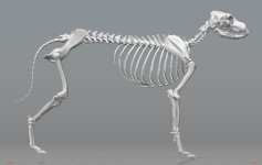
Robotics Project: Snuggles, The Wolf

Accelerometer experiment prep:
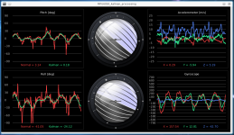
I'm still reading about the sensor, and how poeple have already used it, their code, etc., and collecting links and code and info (largely collected here in this post) so I haven't actually powered the breadboard up and loaded anything yet. :oops: I'm still stressed and tired from the last couple of days of exploding world sounds, etc., so I'm having troulbe processing all the stuff in my head (more than usual). Think I am gonna have another nap (whether I want to or not) soon and maybe I'll be clearer after that and can try out some of the code I've found so far just to verify functionality. I'll probalby start with this one
since it's got an easy visualization method.


I've attached the datasheet and register sheet for the chip on the accelerometers; I have the MPU6050 version so it only uses I2C (the 6000 has SPI as well, and can talk faster to the system MCU). The actual boards being used are labelled HW-123.
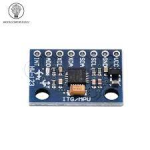
1704148437598.png
they're actually 6-axis, not three, meaning they ahve a 3-axis accelerometer and a 3-axis gyro, which is one reason I picked these out of the varous cheap ones. They can be used for vibration and motion detection, and for position change detection, all of which I need. They also have an i2C input for a 3-axis compass but I don't need to know absolute direction, just relative. (it might be useful to have the compass to "calibrate" from but it's not required).

It also has a temperature sensor, which could be useful to know which sensor locations are "in contact with" the user, if they're snuggling with it (since this setup can only detect the change in motion, position, contacts, etc., not a continuing stable contact or touch).

It's likely that after I get done reading the dozens of pages of the spec sheet I will have some idea of what preprocessing the onboard MCU can do for me, as it already has tap detection, low-pass filters, gesture recognition, etc., so if all these things are really user programmable, then each sensor board can be told how it should respond for specific types of input, and provide specific outputs for some of the things that the first and second level MCUs then won't have to process (since those will still have to monitor the actual sensor data for relative positions, etc.)

It's mentioned in one of the sources below that there are issues in teh raw data of "yaw drift" but that the onboard MCU can use some built in processing to eliminate this problem. The same source also describes a problem I know nothing about yet called Gimbal Lock and the solution it already has built in called Quaternions that it calculates and outputs. Another source explains
The MPU6050 system , because it has both an accelerometer and a gyroscope, allows the use of a Kalman filter , in other words a recursive algorithm. Since I'm not an outstanding mathematician, I don't dare to explain in detail how it works, but to put it simply, it uses gyroscope data to correct the data read from the accelerometer, thanks to which the whole thing works extremely stably. If you want, you can read about it here: Pitch & Roll Readings and the Kalman Filter

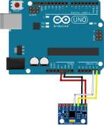
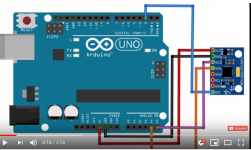
The fritzing wiring diagram
Arduino-MPU-6050_Fritzing_Wiring_Diagram.png 1704149952349.png
and the adafruit arduino library for the chip,
as a github master code zip attached at end; it's dependencies are:
* [Adafruit BusIO](https://github.com/adafruit/Adafruit_BusIO)
* [Adafruit Unified Sensor Driver](https://github.com/adafruit/Adafruit_Sensor)
* [Adafruit GFX Library](https://github.com/adafruit/Adafruit-GFX-Library)
* [Adafruit SSD1306](https://github.com/adafruit/Adafruit_SSD1306)

and the electroniccats version
Another with tutorials

1704151346118.png


Other useful links.


This looks very useful, but I can't understand a bit of it (it's full of math)


I like the howtomechatronics because they actually show how to visualize the readings in a simple 3d live animation on the PC from data send over the serial.print command. That means taht code could probably be used to create a stick-figure wolf that could show the data from the entire skeleton (but if not, it still means it is not "that hard" to visualize what the sensors see.

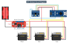
the tutorial continues in a self-stabilizing platform / gimbal
that is probably also useful; it even uses the same servos I already have. (though I don't need to build such a device, the principles can be used for keeping the head steadier as the body moves, if the "wolf" is looking at something while moving. )

For those that ride with their cameras on their EVs, this device could be used to keep the image stabilized to at least some degree but as noted in the article, the servos aren't as smooth as hte motors normally used for this type of device.

Another useful article there is

is linked from the above article, and appears be a very useful site; I think most of the things I have to use are capable of i2C (the rest seem to be I2S but I'm not yet certain).

For anyone that wants to play around with these, aliexpress is the cheapest way to get a few (I think I put a link to where I got them early in the thread) but if you want them fast and buy from amazon already
Amazon.com these only cost about three times as much as AE; Iv'e bought a handful of things from HiLetGo store the last few years and had no problems with them yet. (couple of nanos, some microswitches, I forget what else).


General specs

5.1 Gyroscope Features
 Digital-output X-, Y-, and Z-Axis angular rate sensors (gyroscopes) with a user-programmable fullscale range of ±250, ±500, ±1000, and ±2000°/sec
 External sync signal connected to the FSYNC pin supports image, video and GPS synchronization
 Integrated 16-bit ADCs enable simultaneous sampling of gyros
 Enhanced bias and sensitivity temperature stability reduces the need for user calibration
 Improved low-frequency noise performance
 Digitally-programmable low-pass filter
 Gyroscope operating current: 3.6mA
 Standby current: 5µA
 Factory calibrated sensitivity scale factor
 User self-test

5.2 Accelerometer Features
 Digital-output triple-axis accelerometer with a programmable full scale range of ±2g, ±4g, ±8g and
±16g
 Integrated 16-bit ADCs enable simultaneous sampling of accelerometers while requiring no external
multiplexer
 Accelerometer normal operating current: 500µA
 Low power accelerometer mode current: 10µA at 1.25Hz, 20µA at 5Hz, 60µA at 20Hz, 110µA at
40Hz
 Orientation detection and signaling
 Tap detection
 User-programmable interrupts
 High-G interrupt
 User self-test

5.3 Additional Features
 9-Axis MotionFusion by the on-chip Digital Motion Processor (DMP)
 Auxiliary master I2C bus for reading data from external sensors (e.g., magnetometer)
 3.9mA operating current when all 6 motion sensing axes and the DMP are enabled
 VDD supply voltage range of 2.375V-3.46V
 Flexible VLOGIC reference voltage supports multiple I
2C interface voltages (MPU-6050 only)
 Smallest and thinnest QFN package for portable devices: 4x4x0.9mm
 Minimal cross-axis sensitivity between the accelerometer and gyroscope axes
 1024 byte FIFO buffer reduces power consumption by allowing host processor to read the data in
bursts and then go into a low-power mode as the MPU collects more data
 Digital-output temperature sensor
 User-programmable digital filters for gyroscope, accelerometer, and temp sensor
 10,000 g shock tolerant
 400kHz Fast Mode I2C for communicating with all registers
 1MHz SPI serial interface for communicating with all registers (MPU-6000 only)
 20MHz SPI serial interface for reading sensor and interrupt registers (MPU-6000 only)

5.4 MotionProcessing
 Internal Digital Motion Processing™ (DMP™) engine supports 3D MotionProcessing and gesture
recognition algorithms
 The MPU-60X0 collects gyroscope and accelerometer data while synchronizing data sampling at a
user defined rate. The total dataset obtained by the MPU-60X0 includes 3-Axis gyroscope data, 3-
Axis accelerometer data, and temperature data. The MPU’s calculated output to the system
processor can also include heading data from a digital 3-axis third party magnetometer.
 The FIFO buffers the complete data set, reducing timing requirements on the system processor by
allowing the processor burst read the FIFO data. After burst reading the FIFO data, the system
processor can save power by entering a low-power sleep mode while the MPU collects more data.
 Programmable interrupt supports features such as gesture recognition, panning, zooming, scrolling,
tap detection, and shake detection
 Digitally-programmable low-pass filters
 Low-power pedometer functionality allows the host processor to sleep while the DMP maintains the
step count.
5.5 Clocking
 On-chip timing generator ±1% frequency variation over full temperature range
 Optional external clock inputs of 32.768kHz or 19.2MHz
 

Attachments

  • MPU-6000-Datasheet1.pdf
    1.6 MB · Views: 0
  • mpu6050-master.zip
    497.7 KB · Views: 0
  • Adafruit_MPU6050-master.zip
    339.7 KB · Views: 0
  • MPU-6000-Register-Map1.pdf
    899.9 KB · Views: 0
  • Arduino-MPU6050-dev.zip
    27.3 KB · Views: 0
Had a short nap, not sure it helped yet: Been trying to get the various MPU6050 libraries installed into the Arduino IDE v2 (whatever the latest selfupdate is), but some of them don't show up in the library list in any of the three places there are for that, and don't come in Library.ZIP files to install that way, and aren't structured on their github/etc pages in a way that the Arduino IDE can find and install them that way. Supposedly for these cases you copy the whole folder for those into the sketchbook /library folder but this does not work for any I have tried so far. (like this Usage | I2C Device Library )

The few troubleshooting guides I read so far don't point me in the direction of solving this, and it's pretty frustrating that there's no simple manual way of fixing it such as adding folders to a list in a text file, etc.

EDIT: Ok, after sixty bajillion restarts of the IDE (but changing nothing else), the libraries finally show up in the Sketch-icnlude library menu function but still can't be "installed" into the IDE itself (don't show up in Library manager) so they would simply always be available, and as such any other library that references them (at least one that I found so far) that *is* shown in the library manager can't be installed as the dependency it has on non-installable libraries "can't be resolved" according to the error messages...but there is no option anywhere for a manual resolution, which would be quite simple, to just LET ME POINT IT TO THE FILES!!!!!!!!!.

Whoever creates this IDE doesn't appear to consider the user very much, if at all, or make it very friendly to use when there are errors. I would expect, especially for something intended even for use by noobs, that it would try to walk you thru the process of finding the stuff it can't automagically find, and that it would also remember these finds and their locations for other errors about the same files. But it has no ability or option for this. I won't go into my "programmer" rant again...but I'm sorely tempted. :/

For now I'll just go work on something else completely unrelated (that requires physical interaction that I'm much better at), as I'm now too tired of dealing with this to play with the probably-now-working-able-to-load libraries and example code for this stuff. :(

Aaaaarrrrggghh..
 
Last edited:
Regarding how the weights work within the system, I was kind of thinking they might work (or could be able to work) like...Hmm. Analogies *are* hard. How about: a flexible surface (rubber sheet?) that a set of "decision balls" have to pass across and end up in one of a number of possible outputs, starting from one or more of a number of possible inputs. Different weights at different decision points scattered all over the surface attract (positive weights) or deflect (negative weights) the path to cause a tendency for them to pass more to specific end points from some starting points, and more to other different end points from other starting points.

Are either of those even remotely realistic? :oops:
This actually sounds basically like the way artificial neural networks function in general. The process of training a network model is literally trying different weights repeatedly, over and over, until you find a set that basically does what you want it to do. The algorithms for what weights to try and when get kind of complicated -- it isn't totally random as you train it -- but generally speaking, you're describing all artificial neural networks. Complex models, like GPT-4, include little tricks that help it learn to bypass entire layers of weights when they aren't useful for a particular task.

I think your best bet would be to have different models for different behaviors though. As far as how you'd tie them all together into a functioning whole, well, the devil is in the details; but tying them all together is a lot easier than the rest of the project (at least from my perspective). That's actually how animals (and people) do it too: we have specific clusters of neurons and nervous system tissue devoted to very specific functions, and we also have very generalized clusters that we can use in very general tasks. Just look at some of the incredibly odd behavior that people exhibit when suffering from traumatic brain injuries: things like only being aware of the right side of the world around you, i.e. eating only half a plate of food and acting as though the left side of the plate doesn't even exist. Really bizarre things happen sometimes when people get brain damage.
 
This actually sounds basically like the way artificial neural networks function in general.
Ok...I figured I was completely misunderstanding them, so I'm glad I didn't totally miss all the points in the stuff I've tried to read and videos I tried to watch. (stopped by the math in all cases at some point).


The process of training a network model is literally trying different weights repeatedly, over and over, until you find a set that basically does what you want it to do. The algorithms for what weights to try and when get kind of complicated -- it isn't totally random as you train it -- but generally speaking, you're describing all artificial neural networks. Complex models, like GPT-4, include little tricks that help it learn to bypass entire layers of weights when they aren't useful for a particular task.

Are the weights something created by the software itself in response to your inputs (reward/reprimand?), vs it's decisions for a given set of sensory input conditions?

Or are they something you have to manually write and create over and over again? (because I could almost certainly never do that)

(these are things I never got to in any of the stuff I've read, as none of them got to those parts before I was lost in math)


I think your best bet would be to have different models for different behaviors though.
So have indivdiual "AIs" to run different things? (using AI as short for "model", or one separate completely input-processing / decision-making "dataset"; if that's wrong I jsut need a definition of "model" I can get a handle on).

Meaning, one AI "runs" the vision input and object recognition, along with specific decision-making that relies on those inputs; anohter AI runs the sound input and sound/voice recognition and those decisions, and another runs the IMU sense network for position/speed monitoring (proprioception) and another runs the IMU-based vibration/touch sense network, etc? Then a "master" AI that takes all the decisions and interpretations all of those have made as inputs, and outputs the control signals to a set of AIs that operate the motors, speakers, etc?

If so, that's the way I kind of envisioned it...partly because it breaks it down into bits and systems that can be built and tested initially individually (even if they're not completely functional until integrated), whereas a single comprehensive AI would have to all be working before any of it would work, and that wouldn't be very much fun to do.


Or...do you mean that there would be individual AIs for actual individual specific actions? Such that there would be an AI for reacting to inputs that causes waving a front paw, and another that causes "stomping" the paw instead, and anohter that causes dipping the head , and another htat causes shaking it, etc.

If so...I'm not sure I can quite visualize it, but it would be like a bunch of overlapping funnels that all take the same input data from all the sensors, and each one processes it differently, even ignoring some of the inputs, or filtering out significant amounts of the information from that input, before it enters its' decision matrix (I was going to say decision tree, but AFAICT these things don't work anything like if-then trees do, from what I recall of my ancient BASIC days).


As far as how you'd tie them all together into a functioning whole, well, the devil is in the details; but tying them all together is a lot easier than the rest of the project (at least from my perspective).

I can envision how the first version I mentioned above would be tied together, but I have not figured out enough of how the second would work to do that.


That's actually how animals (and people) do it too: we have specific clusters of neurons and nervous system tissue devoted to very specific functions, and we also have very generalized clusters that we can use in very general tasks. Just look at some of the incredibly odd behavior that people exhibit when suffering from traumatic brain injuries: things like only being aware of the right side of the world around you, i.e. eating only half a plate of food and acting as though the left side of the plate doesn't even exist. Really bizarre things happen sometimes when people get brain damage.
Yes, I have done some reading, etc., on such things over the decades; at first I had a hard time believing some of what I read, but then I realized that this kind of thing made quite a bit of sense out of all the differences between how I think and react and feel vs how "normal" people do (my brother would say "neurotypical" for them, vs neurodivergent for me and himself, though I think that I am significantly more divergent than he is).

It has made one "small" part of my brain (which seems to use various bits to process a lot of different datasets in the background and eventually spit out some research results to my "concious" brain) ponder how brains work and do what they do...which is part of what led me to where I am now with this project (although I didn't iknow what techology could do it, I knew that there would be something, eventually if not yet).
 
Last edited:
Sidechain:


I have a very wierd brain that I do not have control of, really...I can put in requests for things, but it kind of does what it wants. I am not sure how to explain it to anyone any better than that; it's very hard to put what I "see" in there in any kind of words or other common-communication method. I often feel like a passenger in it (not dissociation; I know what that's like too after the housefire and other emotionally-intense experiences along the way) where ideas, images, sounds, objects, etc., "come to me", and they don't all exist solely as internal things--some of them are nearly as real as the actual physical world around me, but "obviously" cannot actually be present for one reason or another.

It's much more than just this, but if you have seen any of those scifi movies/etc where they "build" things in 3D holograms moving stuff with their hands in the air inside the hologram....that goes on in my brain all the time, not just with visual things, but mostly with those. (it is one reason it is hard for me to get motivated to do things once I imagine them, because the imagining is often in such detail that I feel I already created it, and have no need to actually do it outside my head; the satisfaction of having done it is already there. The memory is clear that it isn't actually physically done...but the feeling remains.)


It was very confusing when I was very young, but over the years I got used to it and learned to differentiate between the things in my brain and things that physically affect me since most of these things do not "exist" in *all* of the sensory impressions possible at the same time, unlike the physically real world. They're not like hallucinations (which I also experienced a few times, whenever doctors have prescribed something to "help" me...they don't understand me or my brain so nothing they think they know applies to it).

I still have times when all the input from inside my brain plus the input from the physical world becomes overwhelming, and I just can't process it all, and I have to "stop", and not process any of the inputs. I don't know what that looks like from outside me.

I'm sure that all doesn't make any sense; it's incredibly incomplete as there's just no way to put it into words, really.
 
Sidechain:


I have a very wierd brain that I do not have control of, really...I can put in requests for things, but it kind of does what it wants. I am not sure how to explain it to anyone any better than that; it's very hard to put what I "see" in there in any kind of words or other common-communication method. I often feel like a passenger in it (not dissociation; I know what that's like too after the housefire and other emotionally-intense experiences along the way) where ideas, images, sounds, objects, etc., "come to me", and they don't all exist solely as internal things--some of them are nearly as real as the actual physical world around me, but "obviously" cannot actually be present for one reason or another.
It sounds similar to the visual interactive system that was ginned up at MiT in the 00's, they were looking at approach vectors for AI, if you can't model the whole brain, then what can we base our model on? SImply stated it came down to getting with some neuro students and looking at the way humans interact with the software ::taps forehead::
I have a "wierd" memory, I am visually eidetic, I have near perfect video recall of my entre life.. which sounds awesome until you realise I don't even get the Dewey decimal system, just the punks at blockbuster at 11:30 on a friday night. If I can grab the memory, I get the whole things, past that I have to find a known associative node (item I for whatever reason can always recall perfectly and at will) and then ... yep, like a vcr, fast forward the tape until I get to the desired portion. This rocked when I was in my teens, my whole life was only a few hours long... now.. not so much, also all the various trauma events evidently put blockades in your mind (per the lovely Neuro I have kept in touch with) ie: the more trauma, the more your mind refuses to even consider looking at bits of data. Lose a kid to suicide, lose the entire last 6 months of grad school, occasionally I will be able to just grab the point in time, but the old fast forward/rewind seems to completely rebel. My answer was to set time date events on a watch that would pull up a random image for a background. It has helped a lot, but yeah, tale end of grad school is still a wipe, why those 6 months were tied to an even 10 years later is beyond me.
It's much more than just this, but if you have seen any of those scifi movies/etc where they "build" things in 3D holograms moving stuff with their hands in the air inside the hologram....that goes on in my brain all the time, not just with visual things, but mostly with those. (it is one reason it is hard for me to get motivated to do things once I imagine them, because the imagining is often in such detail that I feel I already created it, and have no need to actually do it outside my head; the satisfaction of having done it is already there. The memory is clear that it isn't actually physically done...but the feeling remains.)
Oh no, You are soooo gonna finish the robo-cuddler, If I have to make and ship baked goods until you capitulate.
It was very confusing when I was very young, but over the years I got used to it and learned to differentiate between the things in my brain and things that physically affect me since most of these things do not "exist" in *all* of the sensory impressions possible at the same time, unlike the physically real world. They're not like hallucinations (which I also experienced a few times, whenever doctors have prescribed something to "help" me...they don't understand me or my brain so nothing they think they know applies to it).

I still have times when all the input from inside my brain plus the input from the physical world becomes overwhelming, and I just can't process it all, and I have to "stop", and not process any of the inputs. I don't know what that looks like from outside me.

I'm sure that all doesn't make any sense; it's incredibly incomplete as there's just no way to put it into words, really.
I followed it, might be because I wander through life in my own slightly out of sync buffer zone. If I am not particularly interested in what is going on around me, I can just whistle up a mental model and think about what happens next.

The good side is I can easily remember nearly every life performance I have ever been to... The down side.. I also recall the 90's far far too well
 
Well, I've now been fighting with the Arduino IDE 2.2.2 for several days to compile a the "simple" howtomechatronics demo previously linked, with many errors. I can fix one by following what worked for one person in troubleshooting posts around the internet, only to introduce many new ones, and I don't yet understand enough of how this all works to figure any of them out on my own. So this is going to take (quite) a (long) while to even begin to get started. :(

Not posting the errors here, as they are quite voluminous and would make this thread unreadable. :(

At first I thought it might just be a library version problem, as in where a particular library came from / was written by, but I've now tried multiple versions of the libraries in question (I2C and MPU6050) with no fix, only different sets of errors. Hand edited various files in the libraries to remove (comment out with //) "conflicting TYPEDEF" lines per instructions found on various sites, again, just different (larger) sets of errors.

Most other errors are along the lines of "warning: ISO C++ says that these are ambiguous, even though the worst conversion for the first is better than the worst conversion for the second" and make zero sense to me and the fixes suggested all require actual coding knowlege of how this stuff works, so I can't implement those yet (not for a long long while).

The most complicated sketch I've gotten to actually compile and upload and run is BlinkSOS..... :( (which doesn't actually blink an SOS, either, just three short blinks with long spaces, two short blinks with short spaces, and a really long held-on state, then repeating the loop. The code looks like it should do the correct thing, so I swapped all the High and Low statements in it using the Replace function in Notepad2 (windows notepad replacement program), and now it blinks correctly in all cases, properly providing the SOS. Why it wouldn't do it with the levelsas they were originally, I don't know--that should only change whether the LED is on or off for the specified time, and not change whether it does the specified thing when it's told to do so. But it worked, at least.

I modified the code to include a few seconds worth of very rapid flashes at the end (copy/pasting one blink code cycle modified for 1/10 of a second on and off states), and that compiled, uploaded, and runs. So I've managed to do something other than a raw example sketch, and prove the board itself (NodeMCU v3) actually functions enough to do this, at least.

Now back to the frustrating part of figuring out why the MPU6050 demo won't compile. :(
 
Finally success:

I cleared out the whole libraries folder, then put in JUST the I2Cdev root folder / files, and the MPU6050 root folder / files into it.

Then loaded the libraries\MPU6050\examples\MPU6050_DMP6\MPU6050_DMP6.ino and verify/compile still gives a bunch of red warnings that I don't know what they mean, but it compiles, and will then upload with no errors into the NodeMCUv3, and it runs.

However, there is no output because presumably it's not getting data from the IMU board. I can't find a single bit of documentation that *clearly* states, without conflicting information in the same place or elsewhere, *which pins* are used, either by default or for this specific demo, on this specific MCU board, for the I2C SDA and SCL lines, or for the Interrupt#0 line. Using any set specified anywhere I find it stated doesn't work, so I tried a second IMU board in case I'd done something to the first one, no change.

Since the specific diagrams on the demo page are for the Nano, I got that out instead, since I have a few originally intended for the never-completed (barely started) Cycle Analyst Nano Tidbits project (thread around here someplace), and stuck all this on a separate breadboard by itself, wired the way the diagram on the demo page indicate. Setup the IDE for a Nano and the port it comes up on, compiled and uploaded, (zero errors or warnings, BTW), and it then starts, runs, and begins spitting out the YPR (yaw pitch roll) values live on the serial monitor as I move the breadboard around, and they appear to be valid data.

::whew:: :bigthumb:

For the other part of the demo, to view this live in Processing, I haven't gotten that to work yet, I can change the port and datarate in the Processing sketch to the correct one, but if I leave the IDE running it locks the serial port so the Processing can't read it, so I have to close the IDE (closing just the serial monitor doesn't work), and then at least the Processing (heretofore "P") sketch runs and brings up the display window with the bar to be controlled via the data from teh IMU.

However, nothing ever changes, so either the data isn't coming thru correctly, or the sketch isn't working right, or...who knows.

BUT: since the code on the Nano reads the IMU and sends it's data out, it is sufficient accomplishment for the moment, since I don't need the P stuff to work; I just wanted, for now, to know that the IMU could be read, etc.


I suppose one possible next step would be to get it to read two IMUs and spit out their data as two sets. (this requires figuring out how to change the I2C address of just one of the IMUs so they can be on the same bus, or figure out how to use separate buses, or one of those data bus expander boards I got for this eventuality, etc).

Maybe a simpler task would be to get it to not just show me the current inclination of the device, but the speed at which the inclination changes. (I'll need that data for motor control, as well as the inclination, and this IMU can do both of these).

At some point, once I have both the inclination and speed of change working, then I can figure out how to compute the differences between the two IMUs and store that as data somewhere, that would eventually be used to map their relative positions from a known starting point, which would be a beginning to the necessary data processing for the Proprioception Network.

I have no idea how to do that, yet, but...everything I need to do it is probably already out there, somewhere, already written or created, if I can figure out where they are and how to put them together. (after I learn how they work...the very hard part)

The speed of change data can also be used to detect vibrations (touches), and those can be localized using that map data, once there are at least three IMUs being processed that are connected to the same physical framework.
 
Last edited:
Ok...I figured I was completely misunderstanding them, so I'm glad I didn't totally miss all the points in the stuff I've tried to read and videos I tried to watch. (stopped by the math in all cases at some point).
You've got a pretty good handle on this stuff, actually; and don't worry about the math, it comes up a lot less often than you might think :)

Are the weights something created by the software itself in response to your inputs (reward/reprimand?), vs it's decisions for a given set of sensory input conditions?

Or are they something you have to manually write and create over and over again? (because I could almost certainly never do that)
That's what frameworks are for. I'll walk you through my latest project: I'm doing a challenge to predict water supply in the western US six or more months in advance. To do this, I'm using several artificial neural network models and a whole bunch of data (satellite data and automated sensor readings for things like snow depth in the mountains, temperature, etc.). I sat down with a huge list of available data, and hand picked the pieces that I thought would be most useful -- that part always takes a lot of domain specific knowledge, so usually at least half of what I do is literally studying science I have little or no interest in, such as hydrology in this case.

Then I sat down to design the rest of the system around that data. I decided to put the data into a matrix, where different data points were stacked on top of each other like channels in standard RGB (red green blue) video streams. So one channel of my model input is each month's snow sensor data, one channel is the average temperature for that month, one channel is the amount of water that flowed through a specific site of interest in a month, and so on. I don't need more than a few months of data to make a prediction, but in order to train the model, I needed data going back to the year 1900 (I'm using supervised learning, which is usually the better method as long as you have all the data necessary to do it; i.e. I'm training the model by showing it examples of what it should output based on specific input data).

Convolutions are a specific type of operation, but you can basically think of it as just taking a matrix (a grid of numbers stacked on each other) and multiplying that matrix by another matrix. It's not actually that simple, but conceptually, you don't need any heavier math to understand it than that. Convolutions are the gold star standard when giving neural networks video data, and since I organized my data in a very video-like way, I figured convolutions would work really well on it. So my model architecture is just a bunch of "layers" of convolution operations, mostly. Here's the actual code to implement a model like this in Python with Tensorflow (which has become much less popular than PyTorch, but they're both AI frameworks):

Code:
import keras

input_layer = keras.layers.Input( shape=(NUM_CHANNELS, LOOKBACK_TIME_IN_MONTHS) )
convolution_layer = keras.layers.Conv1D( filters=32, kernel_size=4 )(input_layer)
output_layer = keras.layers.Dense( NUM_OUTPUTS )(convolution_layer)
model = keras.models.Model( inputs=input_layer, outputs=output_layer )

That's a working Tensorflow model. It will take as input a big grid of numbers (of shape NUM_CHANNELS x LOOKBACK_TIME_IN_MONTHS), and it will output something. Before being trained, what it outputs is totally random garbage (because the "weights" are set randomly when you first create it, so the output is literally random garbage at first). The "filters" is how many different values you want to multiply the input by; in this case, it will use 32 (the filters part) 4 x 4 grids (the kernel_size part), and collect all the results to hand the next layer. So as a concrete example, if NUM_CHANNELS is 7, and LOOKBACK_TIME_IN_MONTHS is 10, the input matrix would look something like this (an actual example from my current project's model input):

Code:
array([[ 0.        ,  0.        ,  0.        ,  0.        ,  0.        ,
         0.        ,  0.        ,  0.        ,  0.        ,  0.        ],
       [16.53356667, 16.53356667, 16.53356667,  0.        ,  0.        ,
         0.        ,  0.        ,  0.        ,  0.        ,  0.        ],
       [18.3596156 , 18.3596156 , 18.3596156 ,  0.        ,  0.        ,
         0.        ,  0.        ,  0.        ,  0.        ,  0.        ],
       [ 0.        ,  0.        ,  0.        ,  0.        ,  0.        ,
         0.        ,  0.        ,  0.        ,  0.        ,  0.        ],
       [ 0.        ,  0.        ,  0.        ,  0.        ,  0.        ,
         0.        ,  0.        ,  0.        ,  0.        ,  0.        ],
       [32.975586  , 29.155859  ,  0.        ,  0.        ,  0.        ,
         0.        ,  0.        ,  0.        ,  0.        ,  0.        ],
       [65.75      , 44.43125   ,  0.        ,  0.        ,  0.        ,
         0.        ,  0.        ,  0.        ,  0.        ,  0.        ]])

Then to train it, you just use Tensorflow again:

Code:
model.fit( input_data, ideal_output_data )

That one call to model.fit() handles updating all the weights for you. You just give the framework the input data for the model, and what you want the model to output when it's given that input data (in this example, "ideal_output_data" is the target output values, and "input_data" is the big matrix of numbers that I described above).

There's a bunch of other boiler plate stuff that's required, and that simple network isn't necessarily useful, but that's how you solve something with a supervised learning method. What makes it supervised is that we're "supervising" what the model should output, by showing it literally what we want it to say when it sees the input data. If all goes well, the model ends up recognizing similarities when it gets asked to output values for input that it's never seen before. That part is very tricky and often doesn't work out very well, lol. That's the whole point though: the model ends up "learning" to produce useful output when given specific numbers that it's never seen before. We call it learning, but it's not really "learning" anything. It just ends up with weights (the 4 x 4 grids it ends up using are the weights in this case).

ChatGPT and all the other crazy-impressive models are exactly like that. The input data is your text, and the output data is what it says. Conceptually it's really that simple (although ChatGPT has 70 billion or more individual weights that it uses, plus hundreds or thousands of layers).

Sorry if I got a little verbose, but this is a forum post, not a whitepaper -- I'm not going to edit my rambling 🤗 Anyway, a model can handle as much or as little as you want it to. So for your project, you could feed a model the sensor data, and do whatever you want with the output: control movement directly with it, or use the numbers it outputs as input to a different model that then controls the movement, or however you wanna design it. You can save trained models, but the weights are attached to the architecture: using bits and pieces of models is possible, but gets very complicated and very useless very quickly.

You can see the project I'm talking about at Water Supply Forecast Rodeo: Development Arena if you're interested (including my score and stuff), but it's not really relevant, to be honest.
 
Your verboseness ;) makes this more accessible to me, so I appreciate the rambling.

If the math isn't directly important to understanding these things, then i will try rewatching the videos/etc and ignoring the math the same way I have to when watching/reading quantum physics and astrophysics information sources (some of which are fairly understandable without the math, as long as you don't actually want to *do* anything with the info besides understand the general ideas).

I'm beginning to see what you mean about the weights being essentially inseparable from the behaviors...so I am thinking that separate Ais would be needed for separate behaviors, so that one could choose diferent behavior sets for a particular companion, without the end user having to "raise it from a newborn puppy" in every case to get the end-behavior they want (as they would have to know how to do this and have the patience, and tha'ts unlikely--I don't, and I'm pretty patient, as I have done and still do this for real dogs!).

I would like something...I'm not sure how to describe, because I guess it's not evolved in my head yet. An "app" of some type (preferably on the PC so it wouldn't become useless as fast as it would on a phone/etc), maybe just code that runs in Processing (which is fairly powerful as a UI-creation DE from what I can see in various projects out there) or similar, that could be "packaged" with that for end-users.

Anyway, however it is created / distributed, this app would be a control panel for behavior that creates and modifies a "personality". If specific behaviors can be placed in a selection menu to be included, that could be turned on and off, that would be good. Sliders or dials for how much of a general "personality trait" would be useful: Laziness vs hyperactivity, for instance, or playfulness vs strict obedience, smart-puppy vs derpy-puppy, strong vs weak, quick vs slow, (the latter two done via turning certain motors' power / responsetime up or down) etc. Preset personality types could be built from these, available from a list, and then those customized by the end user with this app, and saved as new listings. Existing personality / memory sets of a particular robot could also be saved as new listings, to be used to "restore" those to fix an ohterwise unfixable behavior problem, or to isntall into a physically new robot (if an old one has to be replaced completely for some reason).

I don't know how the models and datasets would need to be created and separated for this kind of thing to work...but it should be possible, somehow. Talking out of my ignorance: Layering models or cascading them, so that each type of behavior would be it's own AI that creates it's own dataset to process inputs with, and the personality is created by the interactions of all of those layered or cascaded models. So you could change out one model and it's associated dataset for another version of it with different weights/etc., and the personality would change by that behavior's influence on the final output.


Keep in mind...I'm not necessarily trying to use existing known technology or methods to do somethign tehy can't do...I'm trying to do a specific kind of thing that will probably need these things to be used in way they may not have been used in yet to process the input in the ways required to get the output desired. :)

Maybe it isn't yet possible to do these things....in that case, I'll need a whole new technology or method, which I probably can't create. But someone will, eventually, if I can get them thinking about it. It's probably not impossible to do any of these things...just probably not very easy. :oops:

Very few things in the world work "the way they should", for me, but most of them *could* be made to work as required. I don't know the details of how most of them work inside to be able to change them; the ones that do are ones I change as I have time/energy/money to do it, but that's not many. Most things I have "artistic differences" with ;) are software problems--poor design of workflow or UI, mostly. But almost none of those are open-source so I couldn't change them even if I knew the coding for it; I'd have to write the software completley from scratch to do it, and I wouldn't have the time to do it even if I knew how.

Kinda like this project. :) But this project is different, in that there isn't anything out there like this, so there's not much choice about having to do it myself (or with help from those like you that are willing to contribute time to it).


In experimental news, I'm presently wiring up the electronics and motors for this demo


without actually building the gimbal, since I don't need one...but I can use this to then alter the code experimentally to learn something about feedback from IMUs to move the motors. Since I still know almost nothing about what I am doing, it will probalby be more frustration than fun, but I will learn something from it that I am not learning by trying to learn coding directly.
Then I'm going to play around with the robot arm here
that is controled via a Processing GUI
and see what I can learn from it to apply to building a virtual wolfy in Processing that can display data from the wolfy sensors, and be used to control the wolfy motors, and modify the control inputs using that data. (so that if for instance a motor pushes a paw into an object that would be detected by some of the sensors, and hte Processing UI would then prevent the motor from pushing any further, and then reverse the action a bit to pull the paw away depending on the type of sensor responses).
 
I would like something...I'm not sure how to describe, because I guess it's not evolved in my head yet. An "app" of some type (preferably on the PC so it wouldn't become useless as fast as it would on a phone/etc), maybe just code that runs in Processing (which is fairly powerful as a UI-creation DE from what I can see in various projects out there) or similar, that could be "packaged" with that for end-users.
And there's the issue. Sometimes you need to compromise: what you need is the end behavior to be lifelike. Making the life that it's like customizable like a box of tools (i.e. which living dog's personality it behaves like) is a bonus, from my understanding of what you're trying to accomplish. Don't get me wrong, it's absolutely possible to do, but it introduces a level of complexity that's an order of magnitude beyond what it needs to be.
 
I guess that would be Mk II. ;)

For now, I'll concentrate on the prototype....but wherever you think you see a way I could make the prototype in a "modular enough" way to make Mk II easier to do later without "starting from scratch".

Although...maybe by that time enough will have been learned in making the first one work that a completely new approach might be found anyway. :/

Eh, doesn't matter. As long as a version of it gets done, it can be improved later. :bigthumb:

So I'll keep poking at the hardware to figure out how to use it to do the sensing I need...then if you're up for it maybe you can help me work out the software needed to "map" the senses onto the body and localize specific inputs.

Once that's possible, then something can be created to cause reactions to that input.

The actual robotics to move the body around shoudn't be difficult, though it might be expensive and complicated.

hopefully I'll end up with something that can snuggle (on it's own) like JellyBean is right now (she almost never does this, and almost never for more than a few minutes before she just leaves):
20240110_203434.jpg20240110_203337.jpg

Where right now I can pose it and snuggle up to it, it's just not the same (hence, this project):
20240107_111355.jpg
 
Eh, doesn't matter. As long as a version of it gets done, it can be improved later. :bigthumb:

So I'll keep poking at the hardware to figure out how to use it to do the sensing I need...then if you're up for it maybe you can help me work out the software needed to "map" the senses onto the body and localize specific inputs.
Be happy to, my friend. Just send a private message so I don't miss the email about it :)
 
Ignoring the math stuff in this video
I managed to get an hour into it so far, though I still don't think I really understand them yet.

But they mentioned at this point
they mention that CNNs (convolutional neural networks?) can be made to learn to do something by watching youtube videos. (presumably any video source). If this is the case, would it be possible to use this method to teach it how to move and behave like a wolf, by feeding it selected videos of them sleeping, moving, playing, etc?
 
While I still don't fully understand it, a few minutes later they describe the concept of Pooling with CNNs, and this convolution and pooling sounds like the way the data from these IMUs will need to be processed to generate the Proprioception Map?

I still don't have any handle on what kind of math functions would need to be done to any of it to make that map--I can easily visualize the data itself generated on the body, and the map itself within the software, but I don't know how to get from one to the other, or how to describe what I can see in my head well enough to get it across.
 
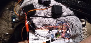
I got the basic version of the gimbal project
linked previously wired up, Nano, IMU board, and three servos (each with a different "arm" on it so I could see them moving and recall which was which),
1705028880053.png

and ran the basic code for it, and it "works".
20240111_195839.jpg

Now I'm learning which parts of the code do what, and am just playing with how each section works, changing things to see what effects they have, until I break something, and then sometimes figuring out why it's broken, and sometimes I can't and just restore the original code and start again. :oops:

But...I am learning (like a badly written AI :lol: ).

JellyBeanThePerfectlyNormalSchmoo is bored with it all (like she is with everything else in the universe)
20240111_195847.jpg
 

Attachments

  • DIY_Arduino_Gimbal_Code_-_Based_on__MPU6050_DMP6_Example.rar
    3.3 KB · Views: 0
Dropping myself a note here for a page on how to calculate required servo sizes
for when I get the skeleton designed and built (or printed) and weights guesstimated.

There is a LOT of math involved :cry: ....but the formulas appear to be already there, and just need me to fill numbers in. That I can do, and then the actual math can be done with a calculator. I hope.
 
Also leaving myself this link
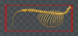
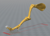
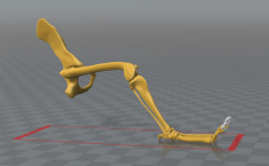
for the only free 3D model of a canine skeleton I can find that is actually potentially useful. It also happens to already be STL format. It's not a great model for actual accuracy, but it doesn't have to be. I don't actually need all the parts, either, and the actual joint ends are somewhat irrelevant, mostly I wanted something that is pre-curved as the bones actually are, so that it has a more realistic shape to the limbs, just because I can, with the 3D printer.

1705039868323.png 1705039882095.png 1705039899245.png 1705039914293.png


In the previous skeleton experiment, I used old steel tubing and crudely bent it partly by hammering to get an approximation of the bends in the various leg bones, just to see if I could do it; this was before I got the printer, which makes this sort of thing much easier.

I don't think it should need a steel skeleton, and in fact a slightly flexible one would be helpful for snuggliness (although it might complicate motor control if it's too flexible).

I will have to take the model apart to it's individual bones, modify their ends to accept the rose/heim joints I will probably use to connect them (these probably will be purchased in metal versions rather than printed, although I understand it may be possible to actually print them in one piece, which would be interesting).

I don't *require* the paw / wrist bones as individual parts, but since the model has them, I might go ahead and print them, along with a mold for the paw itself, then glue the paw/wrist bones together with silicone caulk, and then position the bone assembly in the mold to cast much softer silicone around it, to make a more poseable paw. If i do this I may go ahead and preattach control cable lengths to the toes, thru guides in the wrist bones, so that I have the option to add control motors to move the toes at least as a group, if not individually.

Most likely any paw motion would be just gripping, so the cables only have to pull from underneath, and springs can be used to tension the top cables to return the toes to "normal" relaxed position. If it is ever "standing" or "sitting up" with weight on the toes, they would then spread out somewhat like actual canine toes. Any servo used to control them could be setup for say, half-rotation as the "relaxed" position, so that it could be relaxed even further on command to allow the spreading.


The spine...I am not sure if it would be better to use the individual bones as in the model, and glue them together with a flexible foam, then run a central cord core to prevent them from pulling apart, and then run motion control cabling along the spine's muscular attachment spars, or if it would be better to use the spiral conduit I used successfully in the previous metal skeleton.

That conduit has enough degrees of freedom and curvature to move in pretty much any way I need this to move. But it doesn't have any attachment points for motion control cabling or guides, so I'd have to clamp something onto it for this in various places along it's length.

A "real" spine model might make that easier to do, if more complicated to assemble. And it would have problems I will have to work out probably during assembly and testing, in the interconnection between each vertebra. I don't know the specifics of what I would use for a compressible foam between them to allow for sufficient freedom of movement, or what I'd use as a central tensioning cord. Control cable attachements and guides should be easy enough to model into the parts directly.

Maybe I'll build first using the conduit and if that doesn't work out with motor control then try the more complicated "actual spine".
 
Last edited:
they mention that CNNs (convolutional neural networks?) can be made to learn to do something by watching youtube videos. (presumably any video source). If this is the case, would it be possible to use this method to teach it how to move and behave like a wolf, by feeding it selected videos of them sleeping, moving, playing, etc?
So, it's important to remember that when it comes to things like this, accuracy is everything. See, any neural network can be made to do anything (yes, anything) -- the catch is how well it does it. So convolutional neural networks work very, very well on video data because the convolution operation can act on multiple channels at once. Basically it picks out certain "features" (combinations of values) across multiple channels at once.

So the answer is yes, convolutional neural networks can do that. But any neural network can do it. The real question is how well it can do it -- and that's where the design of the model comes in :)

Honestly, most (or at least many) neural networks have at least one convolution in them. It's just an incredibly useful mathematical operation, and it very frequently works out nicely.
 
I'll take your word for all that, because I still don't really know what a convolution is/does, exactly. (maybe I don't need to know, as long as it does the thing I want it to? I dont' understand any of the math of physics, but I use the results of it all the time :) ).


So...i've been trying to figure out how to do the sensory triangulation to localize each specific input, but I am not sure what exactly needs to be done. I think one of these "AIs" would probably do this better than the way I initially imagined (a database and a bunch of if/then loops running on all the data within it...and no, I don't know how that would work either :oops: )


The IMUs have 3 axes of accelerometer (change in velocity) sensing, and 3 axes of gyroscope (change in direction) sensing.

The IMU chips I'm using have both the raw data output available for each of these, and have an MPU that can preprocess this data (but the documentation doesn't appear to explain what this MPU can actually do, or how to use it to do that, so if you can figure that out from the stuff I linked and attached in the posts about the IMU boards previously, could you point it out to me?). The preprocessing is supposed to save CPU load on the system processors, but I don't know how much it does that or how or if it's even necessary (I assume that distributing the CPU load across as much of the system as possible in this way would be better, simply because there are going to be at least a couple of dozen of these IMUs all over the robot, and that is probably a whole lot of generated data, all the time, that has to be processed in realtime.


The accelerometers (AMs) are what detect vibrations, which are what need to be processed to determine whether there is or is not a touch.

(for instance, there will be vibrations from the robot's own movements, from the cable-operated limbs, joints, etc., and those may be able to be filtered out by it learning which of those datasets to ignore and when?)

The AMs also detect the changes in velocity that indicate, for instance, a start to motion, and an end to motion, etc. These need to be processed along with motor control commands to determine which changes are caused by a motor starting or stopping, or an interaction with an outside object (user moving all or part of the robot, some part of the robot contacting or impacting the user or some other object, etc).

The gyros are what detect changes in direction, and this needs to be processed also for the above results.

Together those data can be used to determine where any particular sensor is in relation to any other, and thus where any part of the robot is in relation to any other.

Once that is known and a "map" created and maintained from that data, then the AMs' data can be localised to a specific point on the robot, in a similar way to having mapped an earthquake's epicenter and hypocenter (although I don't know exactly how that is done). A particular vibration may be sensed at mulitple points on the robot, by several sensors wtih varying degrees of response--some of them oriented differently than others so their axes can be compared indirectly for amplitude (how hard was the touch) and waveform (type of touch or impact).


As an example, if the robot lifted a paw so it could be "waved" or "batted" at the user, it would just repeat (non-identically) a loop of movements a few times, something like the way this randomly-found video shows right here
but if there is a vibration that is localized to the paw (not coming from any of the rest of the limb or robot), it would then command the paw to pull back, as that means the paw has touched something.

If the vibration is an intense spike, then if it came from the direction the paw was heading, it is probably an impact and "oops" behavior should be intiated as well (the apologetic dog thing).

If the vibration spike came from above the paw, then the robot should display that behavior and pull the paw back and hold it up in the air against them in "reaction", as it probalby means the paw was swatted away. If it came from below the paw, it was also probalby swatted away, but the paw should then be lifted up and back instead of drawn down and in....etc.

A related part of this uses current sensors in each motor to determine that it's taking more than it should to pull the paw back, and stop trying to, when the user grabs the paw for "shake" or whatever. (partly in cooperation and partly just so servos/etc don't get damaged).

A further related part of this uses AM and gyro data to determine that the paw is now moving on it's own (being pulled or pushed by the user) and the robot should "go along with that" and gently assist this movement (partly in cooperation and partly just so servos/etc don't get damaged).


If the vibration is instead a continous one that "draws a line or path" across the surface, especially repetitively, it's probably the user petting the paw, and response behaviors to that would be initiated.

Etc.

Visual and sound data would also be parts of these things, but that's beyond the scope of this initial description. :)


There would be similarly categorized reactions to each of the many many possible sensed vibrations, etc.


But...I digress...I don't know how to actualy *do* any of these things.


At present, I've been lucky enough to just get the IMU data to run three servos simultaneously on one Nano, in that gimbal demo/project/lesson. :lol: :oops:
 
But...I digress...I don't know how to actualy *do* any of these things.


At present, I've been lucky enough to just get the IMU data to run three servos simultaneously on one Nano, in that gimbal demo/project/lesson. :lol: :oops:
I just want to reiterate and say that very smart, very educated people have tried to accomplish what you're talking about for decades. Virtually all of them have met with what can only be described as complete and total failure. Also, don't misunderstand my background: I did work at iRobot in their government & industrial robots division, but I didn't have all that much to do with programming robots. My job there dealt mostly with the networking portion of a radio control and the mobile robot base unit -- I wrote code responsible for the messages going from the hand-held controller to the robot, and people other than me handled basically everything that you're talking about :censored:
 
But...I digress...I don't know how to actualy *do* any of these things.
Trust me AW... and don't feel like the Lone Ranger. This topic is way,way,way over my pea cranium, but extremely captivating. I'll watch from a safe distance.... stay out of the way,.... and 'try' to learn something.
 
@Papa: Well, you're more than welcome to stick any input you have in anyway, especially regarding mechanical things I'm sure you know more about than I do. :)

I just want to reiterate and say that very smart, very educated people have tried to accomplish what you're talking about for decades. Virtually all of them have met with what can only be described as complete and total failure. Also, don't misunderstand my background: I did work at iRobot in their government & industrial robots division, but I didn't have all that much to do with programming robots. My job there dealt mostly with the networking portion of a radio control and the mobile robot base unit -- I wrote code responsible for the messages going from the hand-held controller to the robot, and people other than me handled basically everything that you're talking about :censored:
I don't really see why it should be so hard (for people that know how to code, build hardware, etc). From my inexperienced POV, it's "just a matter of" :lol: data processing. These various kinds of "neural networks" appear to be very good at DP....

Many much harder things (from my POV) are already commonplace...so if "no one" has been able to make this kind of thing work, either they're all "doing it wrong" which is unlikely (I can't imagine I've got anything in my head that they wouldn't, and probably a lot less), or there's something "impossible" about it at it's core. (which I also don't believe).


So...since assuming it's impossible doesn't get me a Snuggles, I guess the only thing to do is proceed as if it were possible, and start with a simple one-limb version. When ;) that works, add a mirrored limb and processing to combine them. Etc.

I *am* sure I won't end up being able to write all the software myself; the only way I can do this stuff at present is to find someone's project that does part of what I want to do, find another that does another part, and hack them together to see if they'll work that way, etc. Once i've hacked enough bits together I will have learned *something* about how the things work (this is kind of how I learn everything; the only other way I learn is directly working with someone on doing something that they already know how to do, and they explain it all as we go).
 
Maybe this would be a way to use the "video" processing NNs to process the IMU data:

Each axis of data would correspond to an RGB color band.

The data would be mapped onto a(n HDRI if sufficient colorband resolution is needed) pixel map, coordinates determined initially by the "default" startup position of the sensor locations are (where on the body they are located) from a stored initialization map. Position changes would be made to this data based on the actual received data itself.

The map would be a 3D map by virtue of the three "color" bands of data, since each would become an independent pixel in the array. Overlapping pixels will occur if only one pixel map is used for all colors (save memory but increase CPU?) so that the RB values combine in those locations, but since they're still separate data within the pixel data it's easily extracted as needed.

Note that a position map created this way could also be "directly" made viewable for human monitoring and troubleshooting, as you could actualy "see" the shape of the robot on screen within it.

The initial map itself wouldn't actually be a position map as much as it would be a vector map of motion, but this can be used to create a position map from it.

By knowing how fast something is moving (AM data) and direction (Gyro data) the position can be determined relative to starting position and marked on the map.

There are already video filters that can determine what direction a pixel is moving and with what velocity, that can be applied in realtime to real video being watched. I would imagine that something like this could be applied to the data of this map, continously, to generate the speed and direction data necessary for position determination.


If this is done for each IMU module, then the positions and angles of each body part they are attached to can be determined and mapped. If necessary, two IMUs can be placed on each "limb bone" and body segment for either redundancy or cross-verification of data. (three would be better for that last but doubling the data to process is bad enough, tripling it might be unmanageable).


There would be two sets of "video" data to process this way, one for accelerometer AM data, one for gyroscope Gyro data, to keep the color mapping "simple" and separated, so each set of axes have their own RGB channel sets. I suppose you could use luminance/etc for other data channels, but I think those might be better used (if at all) for overall vector data for each set of AM or Gyro data.

I haven't yet visualized how the data would be processed to generate feedback data to the motors to control the system (even without behavioral weighting) for basic positional commands.


It might require adding a magnetometer to each of the IMUs to give full 9-axis data, since the magnetometer can be used to determine an absolute compass direction for at least one axis of data, referenced to Earth Magnetic North/South, and that could be used for a "zero" coordinate reference, to know what angle the IMUs are at in reference to it, in whatever plane they initialize in for that.
 
Maybe this would be a way to use the "video" processing NNs to process the IMU data:

Each axis of data would correspond to an RGB color band.
There's really no need to use modeling for the position of limbs. I guess I left out that neural networks are incredibly slow when compared to old school methods, like formulas and equations. Even if the hardware were able to keep up, the video card in my desktop uses up to 350 watts of electricity to do what it does -- which is more than half the average watts of my ebike (500). Granted, you could have a pretty big battery in a St. Bernard sized body, but it wouldn't last much longer than a short nap I don't think.

The data would be mapped onto a(n HDRI if sufficient colorband resolution is needed) pixel map, coordinates determined initially by the "default" startup position of the sensor locations are (where on the body they are located) from a stored initialization map. Position changes would be made to this data based on the actual received data itself.

The map would be a 3D map by virtue of the three "color" bands of data, since each would become an independent pixel in the array. Overlapping pixels will occur if only one pixel map is used for all colors (save memory but increase CPU?) so that the RB values combine in those locations, but since they're still separate data within the pixel data it's easily extracted as needed.

Note that a position map created this way could also be "directly" made viewable for human monitoring and troubleshooting, as you could actualy "see" the shape of the robot on screen within it.

The initial map itself wouldn't actually be a position map as much as it would be a vector map of motion, but this can be used to create a position map from it.

By knowing how fast something is moving (AM data) and direction (Gyro data) the position can be determined relative to starting position and marked on the map.

There are already video filters that can determine what direction a pixel is moving and with what velocity, that can be applied in realtime to real video being watched. I would imagine that something like this could be applied to the data of this map, continously, to generate the speed and direction data necessary for position determination.
Possibly. Off hand I'm not really sure, to be honest; I don't think I'm following you very well. It doesn't have to walk though, so I still think your best bet is just using simple formulas and not deep learning. I'm talking about controlling the servos, e.g. to explicitly position a limb in an arbitrary position or something; deciding where to position the limb is another matter altogether.

If this is done for each IMU module, then the positions and angles of each body part they are attached to can be determined and mapped. If necessary, two IMUs can be placed on each "limb bone" and body segment for either redundancy or cross-verification of data. (three would be better for that last but doubling the data to process is bad enough, tripling it might be unmanageable).


There would be two sets of "video" data to process this way, one for accelerometer AM data, one for gyroscope Gyro data, to keep the color mapping "simple" and separated, so each set of axes have their own RGB channel sets. I suppose you could use luminance/etc for other data channels, but I think those might be better used (if at all) for overall vector data for each set of AM or Gyro data.

I haven't yet visualized how the data would be processed to generate feedback data to the motors to control the system (even without behavioral weighting) for basic positional commands.


It might require adding a magnetometer to each of the IMUs to give full 9-axis data, since the magnetometer can be used to determine an absolute compass direction for at least one axis of data, referenced to Earth Magnetic North/South, and that could be used for a "zero" coordinate reference, to know what angle the IMUs are at in reference to it, in whatever plane they initialize in for that.
I'm not sure what issues you're currently trying to solve? Maybe I'm just not following you at all, but here's how I see it:

1. Actuators generally report their position, don't they? So I'm not sure what problem needs to be addressed there?

2. Detecting interaction with the environment is a tricky problem, as is processing that data and deciding what position the actuators should be put in. It sounds like you're trying to have it figure everything out every time it gets turned on. I think a much simpler, much more effective way of doing it is to impose certain constraints on the entire apparatus -- as in make assumptions about the design. A pressure sensor on the right foot will always send a signal that is from the right foot, and the place of attachment of that right limb can be assumed to always be to the right of the left foot. So there's no reason to detect whether or not the right foot is to the left of the left foot, or to the right of it (I assume the limbs are going to be too simple to have that much range of motion).

I'm not sure what you need all these sensors for, and if you had all of this data, I'm not sure what you'd want to do with it. Robotics isn't my usual area, but I can at least estimate whether or not something would work well when applying machine learning to it -- and I honestly can't say whether or not all of that data could be processed with neural networks. I'm having too much difficulty trying to evaluate the setup. I'd need more familiarity with the components and the output they produce, etc., as well as some concrete information about what output would be required from the machine learning part of the system.
 
Back
Top