Another Cooling a Currie/Mongoose/Unite MY1018Z thread

TylerDurden

100 GW
Joined
Jan 4, 2007
Messages
7,176
Location
Wear the fox hat.
file.php

These motors are used mostly at 24V, but 36V is manageable and 48V possible if the motor is cooled.

Even if the motor is run at 24V, cooling can help it run more efficiently: it will pull harder, go faster, and live longer simply because the copper windings have less resistance when they are cooler. This is not rocket science. We're just helping the hot air escape the normally closed motor.

It is easy to take the motor apart, just remember where the stuff goes or take notes and pictures as you work. Keep rags handy and have some bearing grease available for the gearbox. Ziplock baggies are helpful to keep parts organized.

I used a 1/2" electric-drill, a rotary-tool (dremel type), a nibble-tool and a 4" abrasive disc.

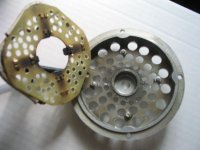
Here's the gearbox-side cover. The metal is soft and easy to work. Wearing gloves and eye protection is advised. Holes were drilled and the nibble tool was used to chew out the rough shape. The edges were smoothed with the rotary tool.
file.php

file.php


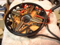
Here's the brush-side cover. The rotary tool is used to narrow the posts where they were staked to hold the brush-plate.
file.php


A tool can be made by flattening a nail and bending it:
file.php


The plate can be lifted by slipping the tool under the plate by each post and turning the tool like a crank.
file.php

file.php


Now comes the fun part!
file.php

file.php

file.php


The drill was clamped pointing up, for the abrasive wheel to sit level. Grooves were made deeper in the ring by moving the ring back and forth while supported on a block. They were not cut so deep as to hit the embedded steel ring, just enough to maximize the surface area. (Ambitious 48V currie-coolers may want to insert 1/2" tall aluminum fins.)
file.php


Imagine you are the rotor... better, eh?
file.php


A hole was drilled slightly larger than the brush-end of the motor shaft. This should permit attachment of an extension of the shaft, so a mechanical fan can be attached. The extension could be brazed, using the shallow hole as a site for a stem to be inserted and brazed around. Crennelations (radial notches) could be added with a rotary tool and cutoff disc for better bite. (The shaft is hardened, so it might break a tap, if you try to put threads into the shaft.) Alternatively, a slow-setting epoxy like JBweld could be molded onto the end by filling a short tube that just slips over the end (cut the tube off after the epoxy sets). Once a stem extends out from the case, a fan could be added by tapping the extension, or making a keyway or flat.
file.php


Time for a cuppa.
file.php


A coffee tin can be easily marked by using the case as a guide. Marking vertical lines will help locate tabs where mounting holes can be made.
file.php


This is a bit tall for a prop-type fan, but might be good for a squirrel-cage fan. The diameter fits the case very well. Being made of metal, it is durable and easily modified. Openings could be made in the sides or end; protection from the elements could be in the form of louvers or screens. An electric fan could be added inside. The tradoffs for electric are minor: electric requires an interface to the power-supply, but it could spin fast even at low RPMs; obviously, the mechanical fan follows motor speed. As ES member The7 points out: there is an advantage to moving the air out at the brush end, to reduce residue buildup on the windings.
file.php


The commutator was cleaned of brush residue by simply securing the rotor-stem in the chuck of a drill and spinning it while gently applying 400 grit sandpaper. Copper dust should be wiped off, especially out of the gaps, to avoid arcing. When inserting the rotor into the stator-ring, be advised: those magnets are strong. To make it easy, the stator should be held to the table by a clamp and the rotor should be held firmly in both hands, out by the slots. The rotor should be in alignment with the gearbox-end bearing as it is lowered into the ring. The magnets will suck the rotor right outta your hands if you do not hold it tightly and support your hands/arms as you lower the rotor. At the point where you are certain the end of the shaft has entered the bearing, you can relax your grip and let the rotor snap into place. Your fingers will probably get pinched, so snug gloves are a good idea.
file.php


The brush-end bearing has a spring-washer to keep the rotor pushing toward the gearbox. Ensure that the bearing can move in and out by pushing it against the spring and letting it return. Any binding should be eliminated, by lubricating with graphite or teflon spray. Fechter's tip on using thin wire to hold the brushes is great, especially if you have holes in the case to withdraw the wires through: it permits screwing-down the cover first (which should have some "spring" to it, before it seats on the ring, due to the spring-washer behind the rotor bearing).
file.php

file.php


Prior to closing this motor, a temperature probe was fastened such that the tip extends into the case just above the windings of the rotor. The probe can be connected to a DMM described in another post: http://endless-sphere.com/forums/viewtopic.php?t=1867 . For testing the difference in temp, the new openings in the motor will be covered with aluminum-foil and readings taken at various loads. The the foil will be removed and the same process will be replicated on another day.
file.php


The motor was installed into the bike using washers as standoffs, to permit airflow into the gearbox side. The required widening the mounting slots in the frame to keep the chainline straight, since the motor would be 1/4" further to the right. Air can flow around the gaps and into the openings. The motor barely clears the chain on the rightside, where the brushes are.
file.php

file.php

file.php

file.php


Some of the members may recall the bike once looke like this:
img_2711_sm_187.jpg


My new urban location required conversion fom Moto-X to urban-assault/ghetto-blaster (tough hood). The paint-job was not intended to look camo... it just came out that way. More rusty-metal primer or dark brown will be added to tone down the desert-camo quality. The crate on the front is very handy to toss the lipos into and the bike balances well. The suspension is a bit soft in front but not sloppy. The stock battery case is empty except the controller. A lipo/avionics case is forthcoming, such that displays and batteries all are carried in at any destination.
file.php

file.php

file.php

The 4" pvc pipe raises the rider up enough to pedal properly and creates a fine place to carry long, narrow items like: golf-umbrella, pipe, mouldings, etc.

Prelim test: 25C ambient
Outbound, WOT, uncovered motor, 3mi. - Temps peaked at 52C, after climbing a long, low grades.
Return, WOT, covered motor, 3mi. - Temps peaked at 56C, after climbing a long, low grades.
Peaks occured when motor was stopped. Running the motor, even under load resulted in temp drop.
Average crusing temperature about 48C

That's all so far.
 

Attachments

  • IMG_3060_sm.jpg
    IMG_3060_sm.jpg
    48.6 KB · Views: 18,018
Great stuff. This looks doable with the tools at hand... How do you plan on securing the brush plate down? Does the swiss cheese fiberglass plate have enough integrity?

BTW how do you get the brushes to behave when reassembling?? I am worried about this point.
 
vanilla ice said:
Great stuff. This looks doable with the tools at hand... How do you plan on securing the brush plate down? Does the swiss cheese fiberglass plate have enough integrity?

Ja mon... the goal is to do this with mostly ordinary tools. :)

The brush-plate was drilled with many small holes (rather than a few large ones) to maintain strength. It will snap back in place and thread-locker will be added for good measure.
 
vanilla ice said:
BTW how do you get the brushes to behave when reassembling?? I am worried about this point.

Not otherwise as drill-happy or ambitious as TD, I used folded tape to hold the brushes in place (2nd pic down), then pulled the tape after putting the cover back on. I left the motor in place and simply removed and drilled the cover. I was concerned about metal road debris and water entering the motor. I plan to add a blower later. Though just the small holes help, without a blower I still need to stop and check the motor temp with my hand every few hard-riding miles.

TD mentioned 48 volts...has anybody tried this motor at 48 volts? I'm thinking since 36v35a is fine with extra cooling, probably 48v20a would be OK too -- but wind resistance with only 20 amps to cut through it would probably prevent the bike from going much faster than at 36volts 35 amps. My speedo says 26mph top speed at 32 volts 35 amps (I use 8 volts 33ah of li-ion in series with 24v 22ah of SLA).

img_2353_146.jpg
 
Thread locker? Thats it?? I was thinking a solder job, or jb weld at the least.

And how are you going to get the brushes to behave during reassembly?

I have a feeling my motor is going to look exactly as yours does... :wink:
 
Ah tape, good one. The debris problem could be taken care of with some add ons to the outside of the case perhaps.

I'm glad I found this forum. The only experience I have with this electrical type of thing is rebuilding a few starter motors for internal combustion engines.
 
It looks that there are 4 magnet poles and if it runs at 3350 rpm,
then the iron core is subjected to an dirve frequency of
3350 X 4 /(60X2) = 112 Hz.
 
Nice machine work TD :D

If you're planning to use a blower, then you really only need one large inlet hole on the brush side of the motor. You want to force all the air to pass over the commutator and windings. Otherwise you'll need to add a 'plenum' to feed the multiple smaller holes.

It looks like the brush holders have small holes near the ends. You can insert small wires into the holes to hold the brushes in.
 

Attachments

  • brush plate.JPG
    brush plate.JPG
    257.7 KB · Views: 5,974
The7 said:
It looks that there are 4 magnet poles and if it runs at 3350 rpm, then the iron core is subjected to an dirve frequency of
3350 X 4 /(60X2) = 112 Hz.
Thank you!

:?: What should we expect if we run the motor at 36V?
 
TylerDurden said:
The7 said:
It looks that there are 4 magnet poles and if it runs at 3350 rpm, then the iron core is subjected to an dirve frequency of
3350 X 4 /(60X2) = 112 Hz.
Thank you!

:?: What should we expect if we run the motor at 36V?

Would expect:

1) No-load rpm = 3350X36/24 = 5000 rpm

2) Drive freq = 167 Hz
Seems still to be Ok for iron core loss at such freq.

If an blower is used, try to blow the brush "dust" out and not towards the coils.
 
*** A fan/enclosure method has been added to the opening post. ***


The7 said:
TylerDurden said:
:?: What should we expect if we run the motor at 36V?
Would expect:
1) No-load rpm = 3350X36/24 = 5000 rpm
2) Drive freq = 167 Hz
Seems still to be Ok for iron core loss at such freq.

I'm guessing if a brave person tried 48V:
1) No-load rpm = 3350*48/24 = 6700 rpm
2) Drive freq = 6700*4/(60*2)=223Hz

Would this still be OK Fe core losses?

Cheers.
 
TylerDurden said:
*** A fan/enclosure method has been added to the opening post. ***

I'm guessing if a brave person tried 48V:
1) No-load rpm = 3350*48/24 = 6700 rpm
2) Drive freq = 6700*4/(60*2)=223Hz

Would this still be OK Fe core losses?

Cheers.

Drive freq of 223 Hz is not to high when compared with Puma at 380 Hz at stock battery.
Jozzer overvolts it to run his Puma at over 700Hz which seem a bit high for iron core motor.

I am also brave (maybe foolish) to double voltage on my AL1020 (from 24V to 48V batterty. But I use Xlyte 20A controller in place of the stock Ananda 24V 15A controller. So far the motor and controller have running well and luke warm.
 
The7 said:
I am also brave (maybe foolish) to double voltage on my AL1020 (from 24V to 48V batterty. But I use Xlyte 20A controller in place of the stock Ananda 24V 15A controller. So far the motor and controller have running well and luke warm.
People here have not gone as high as 48V with the MY1018Z, since the stock currie (ananda) controller FETs are rated only to 40V. More may try 36V if cooling the motor is easy. When a 48V controller arrives, a test and report using the MY1018Z @ 48V can become a new topic.

Thank you for your replies!
 
TylerDurden said:
The7 said:
I am also brave (maybe foolish) to double voltage on my AL1020 (from 24V to 48V batterty. But I use Xlyte 20A controller in place of the stock Ananda 24V 15A controller. So far the motor and controller have running well and luke warm.
People here have not gone as high as 48V with the MY1018Z, since the stock currie (ananda) controller FETs are rated only to 40V. More may try 36V if cooling the motor is easy. When a 48V controller arrives, a test and report using the MY1018Z @ 48V can become a new topic.

Thank you for your replies!

There's lots of cheap 48v brushed controllers available now. Why not give it a try, TD? Cooling or no, I'm dubious it'll live long at 48v 30 amps or more. But 48v 20A could be good....
 
xyster said:
I'm dubious it'll live long at 48v 30 amps or more. But 48v 20A could be good....

This is a true case of a desperate need for MCL. Overvolt and switch to MCL and you can get away with 30 Amps for the peak. This chart is getting posted a lot and for good reason... it's the best way to trick out the little 250's without burning up the motor.

If you tried to use 30 Amps without MCL you would destroy your motor without a doubt!!!
 

Attachments

  • 24V - 30 Amp BCL vs 48V - 30 Amp MCL.gif
    24V - 30 Amp BCL vs 48V - 30 Amp MCL.gif
    9.2 KB · Views: 17,695
safe said:
This chart is getting posted a lot and for good reason...
The only moron posting that bogus chart all over the place is you. :roll:

The key to higher performance is not reducing current, it's reducing losses.
 
TylerDurden said:
safe said:
This chart is getting posted a lot and for good reason...
The only moron posting that bogus chart all over the place is you. :roll:

:lol: With his ill-described, redundant charts and threads strewn all over for him to reference as if they came from more knowledgeable third parties, Safe is his own self-contained cult-of-personality -- narcissistic, in a word.
 
vanilla ice said:
xyster said:
Safe is his own self-contained cult-of-personality -- narcissistic, in a word.

Ah so does that explain the +2pt. bold font then?

Yep -- another manifestation. He seems a decent guy, and knows his stuff in the more traditional bicycle areas. But the know-it-all narcissism tends to get under the skin of people who've been here awhile.
 
*** 1st post updated ***


xyster said:
[safe]...knows his stuff in the more traditional bicycle areas.
I don't think so. I don't think safe has even ridden a bike further than a dozen miles. Safe seems to only view the world through the lenses of spreadsheets and motorcycle magazines. The spreadsheets are missing critical elements in the calculations, such as: hysteresis losses, iron-losses, eddy-losses, thermal latency and the like.

So-called "MCL" is a figment of his imagination, as far as a means to higher performance. Safe seems to think that 50A at 3000RPM generates less heat than 50A at 300RPM.

:roll:
 
Miles said:
Better to be sorry than safe :)

Sorry, safe.... couldn't resist... :arrow:

:lol:
I like your style, Miles -- or Miles of style. :D
 
TylerDurden said:
I don't think so. I don't think safe has even ridden a bike further than a dozen miles.

:arrow: So my BMX, Mountain Bike and Motocross trophies don't count? (20 years ago)

At least I've raced and won... can anyone here say the same?

Has anyone placed above 5th place in any race they entered?

I was never a prolific racer, but for the races I entered I trophied in about 90% of them... 8)
 
TylerDurden said:
So-called "MCL" is a figment of his imagination, as far as a means to higher performance.

I'll prove this one day... you are correct it's all "Theory" at this point, but one day it will be tested.

Hopefully for next seasons riding... :)
 
Back
Top