
mxlemming
100 kW
- Joined
- Jul 17, 2020
- Messages
- 1,125
Edit: update March 2021:
Page 5 for 187A double pulse testing at 16s
Page 4 for ~60A phase for a minute without heatsink
Design has moved to 4 layer board since jlcpcb price difference became negligible
FOC implemented, running well on limited testing with ebike. Current waveforms page 5.
Edit: Update May 2022:
For Project now has
Page 7 sensorless ,
Page 8 crude HFI (needs manual fiddling),
Page 9 field weakening, tracking when PWM disabled
Runs on F405 (VESC) hardware, F401 (e.g. Blackpill) and F303
The F303 board with IPT015N10 has been used for currents up to 100A setpoint at 20s, and doesn;t get too hot with a small heatsink. Peak currents can be run higher.
Edit: update July 2022:
Project now has:
Configuration files for easy setup
Support for SPI absolute encoder TLE5012B
Revised serial interface to enable commands and setpoints
MTPA
Revised circle limitation (voltage output clipping)
Edit: Update October 2023:
Support for ABI encoder
Handbrake with ABI encoder
PWM startup encoder
Hall startup mode
HFI fully functional for salient motors
Field weakening V2 that can run motors up to 2x+ base speed
Terminal access via T-Term by Jens Kerrines
This is now a legitimate alternative to VESC firmware for traction applications and can be installed on most VESC targets (provided you have the original header files and are willing to do some translation).
Hi forum, second post ever. I'm not really an online person, but Hi.
I'm making my own ESC, basically because I like tinkering with electronics and kind of want to for fun, partly because I'm learning software, but also because there wasn't anything vaguely small, cheap and powerful for my EBike... VESC is upwards of 200$ for an original from Trampa, upwards of 65 for a basic Flipsky 4.20 that's really only good for 600W continuous and probably only 10 ish series cells, despite saying 13s.
Edit: I've been running fs 4.2 on 13s, FOC, 60A phase. Not for long but maybe 20km. Credit to flipsky where due.
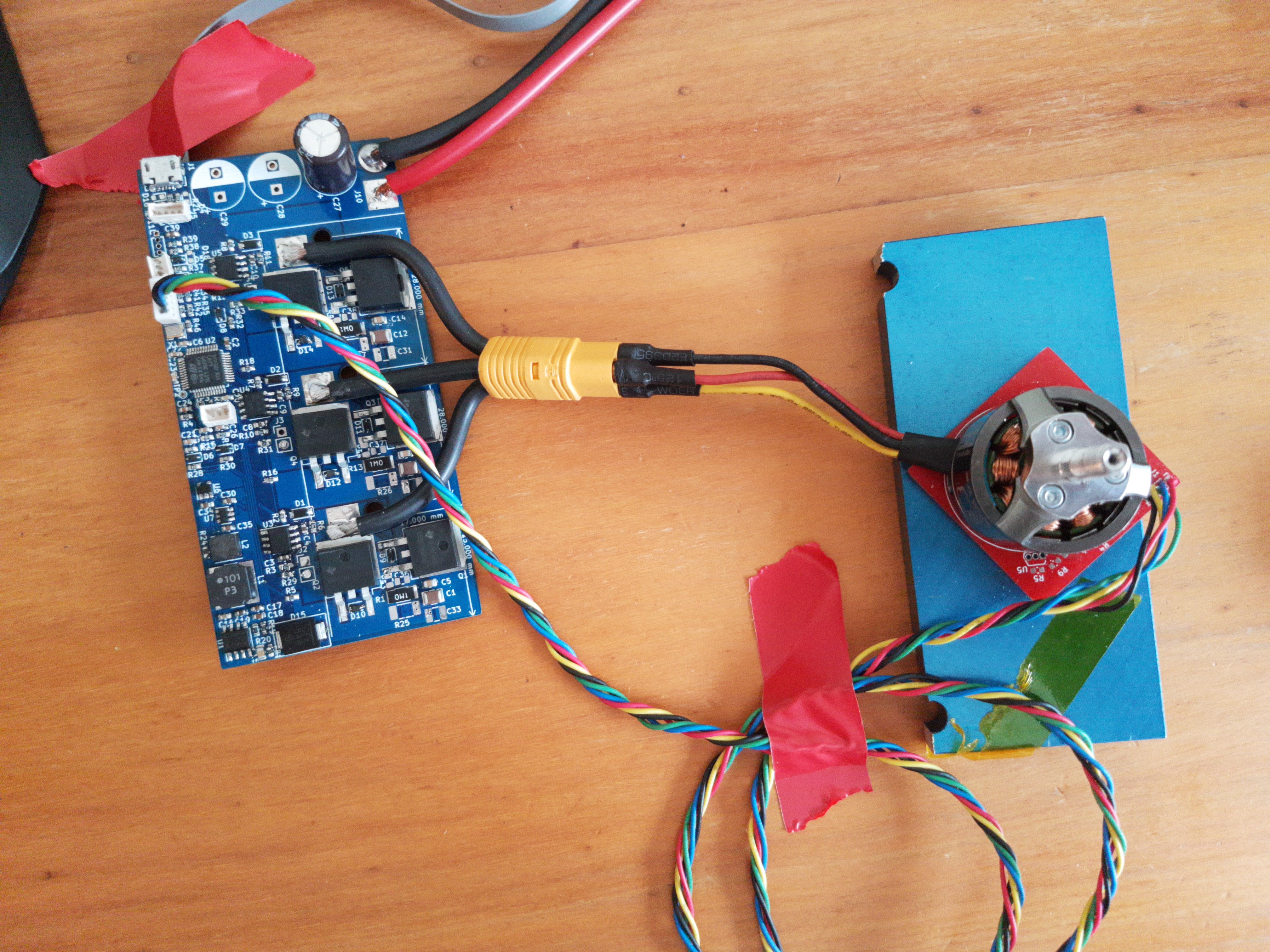
So my target is cheap and powerful and high(er) voltage capable, kind of the same intention as Shaman's Cheap FOCer, but not VESC, and probably substantially cheaper for similar or more power as a result. That's the target anyway.
I'm at the stage where I spun my bike wheel with the R1.0 board. Slowly.
I made the following design decisions:
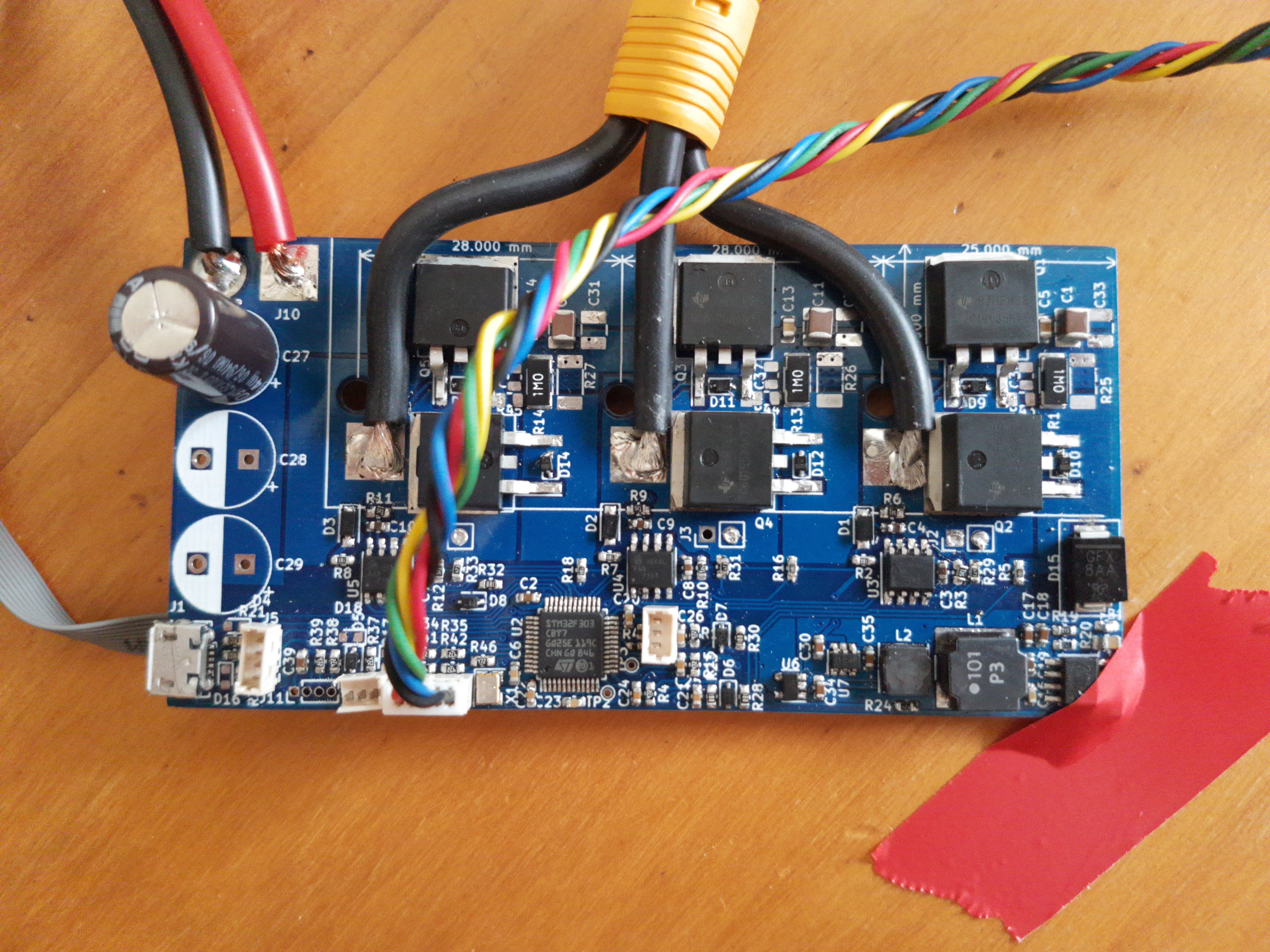
Standard footprint <1$ 600V 4A gate drives and TO263 FETs, no special combined funnyness like DRV chips.
STM32f303CB micro - they're cheap at like 2USD, embed opamps, have an FPU, can definitely run FOC (ST have standard software for it that I have flashed onto an earlier, tiny, non ebike board I made with the same MCU).
I have used a TI Boost converter 5V-12V for the gate drivers, so the upper voltage limit can go to whatever the FETs are rated to, by simply disconnecting the buck converter (snip/DNF a ferrite bead) and powering the logic from 5V on the PWM in, or USB in. Below 60V operation and a TI buck converter can create the 5V rail.
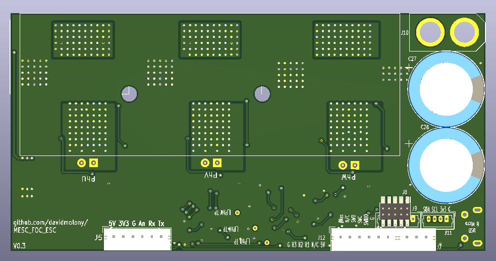
I militantly 2 layer boarded and one sided assembled it, and kept the ground plane as unbroken as possible. Heatsink can be bolted to the underside. I think the BoM cost is below 25$. Think.
I'd like a few bits of feedback/commentary:
1) What are the best connectors, and what do we really want for our EBikes and boards? Currently I've got Molex Picoblades, because my motor had a picoblade put on it by my friend... but I'm sure something else is preferable, those Picoblades are a complete PITA and don't seem very robust either.
a) Hall connector
b) PWM in connector
c) UART connector
d) I have an I2C, 3v3 and GND connection, in case of plugging in an inertial sensor, or interfacing with a BMS or SSD1106 screen thingy
e) There's a USB B micro that is probably not going to change.
2) What other inputs are desireable? (none is a great answer).
3) Any clangers anyone can spot? Appears to work pretty well based on my limited testing so far, but I have yet to run it beyond 20A phase current and 23V, owing to the PSUs I have...
4) How the heck do I bench test a board that'll drive something in the region of several kW of power? How do I sink that much mechanical energy while not riding up a hill (at my desk or in my garage)? I've got a load of car batteries kicking about to generate 48V, so got that side of things covered...
Cheers,
David
Page 5 for 187A double pulse testing at 16s
Page 4 for ~60A phase for a minute without heatsink
Design has moved to 4 layer board since jlcpcb price difference became negligible
FOC implemented, running well on limited testing with ebike. Current waveforms page 5.
Edit: Update May 2022:
For Project now has
Page 7 sensorless ,
Page 8 crude HFI (needs manual fiddling),
Page 9 field weakening, tracking when PWM disabled
Runs on F405 (VESC) hardware, F401 (e.g. Blackpill) and F303
The F303 board with IPT015N10 has been used for currents up to 100A setpoint at 20s, and doesn;t get too hot with a small heatsink. Peak currents can be run higher.
Edit: update July 2022:
Project now has:
Configuration files for easy setup
Support for SPI absolute encoder TLE5012B
Revised serial interface to enable commands and setpoints
MTPA
Revised circle limitation (voltage output clipping)
Edit: Update October 2023:
Support for ABI encoder
Handbrake with ABI encoder
PWM startup encoder
Hall startup mode
HFI fully functional for salient motors
Field weakening V2 that can run motors up to 2x+ base speed
Terminal access via T-Term by Jens Kerrines
This is now a legitimate alternative to VESC firmware for traction applications and can be installed on most VESC targets (provided you have the original header files and are willing to do some translation).
Hi forum, second post ever. I'm not really an online person, but Hi.
I'm making my own ESC, basically because I like tinkering with electronics and kind of want to for fun, partly because I'm learning software, but also because there wasn't anything vaguely small, cheap and powerful for my EBike... VESC is upwards of 200$ for an original from Trampa, upwards of 65 for a basic Flipsky 4.20 that's really only good for 600W continuous and probably only 10 ish series cells, despite saying 13s.
Edit: I've been running fs 4.2 on 13s, FOC, 60A phase. Not for long but maybe 20km. Credit to flipsky where due.
So my target is cheap and powerful and high(er) voltage capable, kind of the same intention as Shaman's Cheap FOCer, but not VESC, and probably substantially cheaper for similar or more power as a result. That's the target anyway.
I'm at the stage where I spun my bike wheel with the R1.0 board. Slowly.
I made the following design decisions:
Standard footprint <1$ 600V 4A gate drives and TO263 FETs, no special combined funnyness like DRV chips.
STM32f303CB micro - they're cheap at like 2USD, embed opamps, have an FPU, can definitely run FOC (ST have standard software for it that I have flashed onto an earlier, tiny, non ebike board I made with the same MCU).
I have used a TI Boost converter 5V-12V for the gate drivers, so the upper voltage limit can go to whatever the FETs are rated to, by simply disconnecting the buck converter (snip/DNF a ferrite bead) and powering the logic from 5V on the PWM in, or USB in. Below 60V operation and a TI buck converter can create the 5V rail.
I militantly 2 layer boarded and one sided assembled it, and kept the ground plane as unbroken as possible. Heatsink can be bolted to the underside. I think the BoM cost is below 25$. Think.
I'd like a few bits of feedback/commentary:
1) What are the best connectors, and what do we really want for our EBikes and boards? Currently I've got Molex Picoblades, because my motor had a picoblade put on it by my friend... but I'm sure something else is preferable, those Picoblades are a complete PITA and don't seem very robust either.
a) Hall connector
b) PWM in connector
c) UART connector
d) I have an I2C, 3v3 and GND connection, in case of plugging in an inertial sensor, or interfacing with a BMS or SSD1106 screen thingy
e) There's a USB B micro that is probably not going to change.
2) What other inputs are desireable? (none is a great answer).
3) Any clangers anyone can spot? Appears to work pretty well based on my limited testing so far, but I have yet to run it beyond 20A phase current and 23V, owing to the PSUs I have...
4) How the heck do I bench test a board that'll drive something in the region of several kW of power? How do I sink that much mechanical energy while not riding up a hill (at my desk or in my garage)? I've got a load of car batteries kicking about to generate 48V, so got that side of things covered...
Cheers,
David
Last edited:
")