New ground-up ESC - MESC_FOC_ESC

Nice big update:
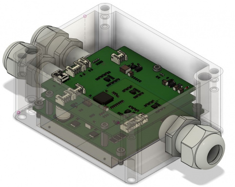
JLC PCB delivered populated boards! Only had to solder another 5 capacitors, 4 chips 2 inductors... Turns out JLC had the chip and inductor parts, but they were so badly categorised I couldn't find them. Grrr.
6kzhmdIwidWQBnoHX699MXWt-GGwrz0RZmE7qjDeG85-oUdxBb45vqRHdQIEcp7lSXQbrS0GheNQKuChn6S8U5TzymHwMv-htykO9R8yxYhb-mvgjE7gt7JmbtzDge6eEEEuHccHlIKI0IBPgJXAIk7hlOwm-49UE7hMm4_cMKK_Lyf4ezscCl32l36wenOukEVXbUI0P9_hkG77-PSjG3d_GEg_djx3OsijdSRVlTbFs1uIknBfAeiKgR1fKirD2Y2XlbtKRpKu7UczTsuavMrxR00Z5KX1TPWxEMff-LMiDoHoFdLP4NDIwaSgrNwgPlcgFMqrZJxQnGjRQzVnX6QjusWf8VBFlatwaxjJIUAu9ySLYNFmTbIrOgNRbdJwESQzRSUTpOpYbE-tO8c71p822zkME5TiZHuL6i1JRNvshXYZ60BDq-hzxkv8CKEotrYUO8aLHPUwvqUIAjb-AmdNiLr2ZK5zScQ5QJqx37vUVsjHF-RSkPuO_hHD6Rm0Vork8yF6SEQXHutXRnRY6fc6gGdjq_d7KasZclhOmer4SQrAJjeS_Eyl-PSyclL7cYU7H3gyvcBEC6K4-7ld4JOpIAX_xAXe2JUk0Quqh1v86WfGN1Ee9CWg_RK5bp9li2V_n-_0KljzJWE4K_SZCdD3cMtDmcL__HaGfS6wXf9jdfc=w822-h616-no


Got duty cycle controlled FOC working. Tried to get current control FOC working, but it all went a bit squiffy. Try again later. Juggling wife, baby, full tie engineering job that Covid has not generated the slightest slack for takes away most of my project time. Think the problem was to do with not being able to read current at 100% duty cycle. TBC. Also not helped that the U phase current readings are poor due to the DCDC converter spewing noise onto it. Have some plans to get around that... mainly use the other ADC channels as default, and apply a filter.
eNblIEv8_yZKBeTwJAWRT2o5UvRJ4KFiAeoHDkoLEmBvuKxs7iRg9HcTImPbDygLGOulUSxCt9h42O9Bk38oh7tTxOIA88L6KZVHnh1KpwuIy8yJGiZN4hDBcOlP3cB3xJ1WofNlnKToAfR_d5XLa0cPRB6gVAbEMlXE-BhAg7bUwKRMuk_dht6UeDocC4VImaefRU_rHMnXU_dVqeA4VXE_BXF5ubGOzX7YbVlz1deEIkdUCzDS-ETxgmCMT4AZazArhODwjbklitBz2QqR-7Ncv9o8D0UjzPmR8_sIzbOHbfJXbhOX5DeWtAu-8wSwhY0XXi4a7p5m1Lrx5h4dDdagLjDU1tbVq3r-4hJznnsm4HtRgbyBC6Wh3DnpiMZDyqK_yB36JzcfwpG_alKkR8wGxh1xIAbggh4OD71eukCWEF9j7KpxBEroJl993_7wYndwKvihA9wwi2PzZscsbWIwVLOlQ4l9HcOxbQw9dyus-iCyS_rJN5KBpNflyWL4ujtyKcnvmXWZCaonPejpWw1_BQfQjjX5n6Fci8SwoiUL6Y0YukKEXN5S40hf7T3XbC2ueJT37aPT91Q3vrTqnMMfjcUrKvOqfbWrYLi0uiDfPzFwJTaS0WeCUVciPpGQeArIjOUiKgm9-FhublPiCRd1X1YB1LOe9ye-8CnXQJgm2YE=w463-h616-no


Here it is spinning away in FOC. Torque is very good.
https://photos.app.goo.gl/Ktq4RAeRV5Ez2vDE6

Turns out FOC really isn't that hard in the end, just 2 matrix transforms, 2 inverse transforms, total of like 20 lines of code when you're not doing sensorless (the hall sensors generate an angle by counting pulses since the last change, which seems pretty robust). There are still lots of little niggly bits, current control, ADC channel management, error handling etc... but fundamentally... it took an extra ~6 hours of knuckle down coding to implement simple FOC. Pretty pleased. Can build on this.

Not all good though, Texas Instruments LM5163 100V DCDC is garbage if you use the "Typical implementation" from the first page of the datasheet. Roughly 10% ripple unloaded, down to about 5% with 200mA draw. Still, it works, and the important analogue bits are running off a linear reg... Guess I shouldn't have rushed that quite so much and done the bare minimum to make the PCB pin compatible with the LM5163 and LMR36510... I mean... it IS pin compatible and technically works with both now :lol:

I'm starting to get pretty hacked of with TI and their burying information half way through datasheets. They screwed me with opamps that phase inverted a while ago (documented in the middle of a pararaph on P33/50), and screwed my colleague with errata on their MCUs. If only some other manufacturer made 100V DCDCs... Any suggestions (looking to On Semi or ST if anyone from those companies read this... :idea: )? Even considering whether the ST VIPer series could be used (weird devices for mains voltages that have inexplicable feedback mechanisms).

by district9prawn » Sep 10 2020 10:51am

Hey congrats on getting a motor spinning from scratch! Your project seems like a great way for people to learn motor about motor control. Arguably easier to get into than the available dev kits made for that very purpose.

Cheers! It's been an on and off PITA, but moments of joy as it first spinnied. Learning so much about coding, power electronics etc.
 
mxlemming said:
Got duty cycle controlled FOC working.

To be honest, I don't understand your arrays. Can you please explain, which array-element contains what?

Why is there a foc_vars.Iab[2] as Ialpha/Ibeta has only two components?!

FOC for dummies

regards
stancecoke

Code:
{
        measurement_buffers.ConvertedADC[0][0] =
            ((float)measurement_buffers.RawADC[0][0] - (float)measurement_buffers.ADCOffset[0]) * g_hw_setup.Igain;  // Currents
        measurement_buffers.ConvertedADC[1][0] =
            ((float)measurement_buffers.RawADC[1][0] - (float)measurement_buffers.ADCOffset[1]) * g_hw_setup.Igain;
        measurement_buffers.ConvertedADC[2][0] =
            ((float)measurement_buffers.RawADC[2][0] - (float)measurement_buffers.ADCOffset[2]) * g_hw_setup.Igain;
        measurement_buffers.ConvertedADC[0][1] = (float)measurement_buffers.RawADC[0][1] * g_hw_setup.VBGain;  // Vbus
        measurement_buffers.ConvertedADC[0][2] = (float)measurement_buffers.RawADC[0][2] * g_hw_setup.VBGain;  // Usw
        measurement_buffers.ConvertedADC[1][1] = (float)measurement_buffers.RawADC[1][1] * g_hw_setup.VBGain;  // Vsw
        measurement_buffers.ConvertedADC[1][2] = (float)measurement_buffers.RawADC[1][2] * g_hw_setup.VBGain;  // Wsw

        //Here we do the FOC transforms - Clark and Park, using the previous sin values, since they were the correct ones at the time of sampling
        foc_vars.Iab[0] = (2*measurement_buffers.ConvertedADC[0][0] - measurement_buffers.ConvertedADC[1][0] - measurement_buffers.ConvertedADC[2][0])*one_on_sqrt6;
        foc_vars.Iab[1] = (measurement_buffers.ConvertedADC[1][0] - measurement_buffers.ConvertedADC[2][0])*one_on_sqrt2;
        foc_vars.Iab[2] = (measurement_buffers.ConvertedADC[0][0] + measurement_buffers.ConvertedADC[1][0] + measurement_buffers.ConvertedADC[2][0])*0.333;

        foc_vars.Idq[0] = foc_vars.sincosangle[1]*foc_vars.Iab[0] + foc_vars.sincosangle[0]*foc_vars.Iab[1];
        foc_vars.Idq[1] = foc_vars.sincosangle[1]*foc_vars.Iab[1] - foc_vars.sincosangle[0]*foc_vars.Iab[0];

        //Now we update the sin and cos values, since when we do the inverse transforms, we would like to use the most up to date versions(or even the next predicted version...)
        foc_vars.sincosangle[0]=sinwave[foc_vars.HallAngle>>8];
        foc_vars.sincosangle[1]=sinwave[(foc_vars.HallAngle>>8)+64];
    }
 
stancecoke said:
Why is there a foc_vars.Iab[2] as Ialpha/Ibeta has only two components?!

https://en.m.wikipedia.org/wiki/Alpha%E2%80%93beta_transformation

There are three components to the Clarke transform.
 
mxlemming said:
There are three components to the Clarke transform.

But the third one (gamma) is never used, as in our system always is
139f411f2f5044561e793b8f5d3ab985a81cc4ef


With this you get the simplified transformation:

36e05ba56ec15de753eb9f3c60983bc874e31370


(quoted from your wikipedia link :wink: )

Can you explain your arrays, plaese?

regards
stancecoke
 
The third zero element is a good indicator of the ADC conversion accuracy. I considered it worth the extra 6 clock cycles, since i can monitor it and see exactly when I get conversion errors,e.g it turns non zero when the pwm saturates.

If you look at the declaration of the array in MESCfoc.h, you'll find
Code:
typedef struct {
	uint32_t RawADC[FOC_NUM_ADC][FOC_CONV_CHANNELS]; //ADC1 returns Ucurrent, DClink voltage and U phase voltage
													 //ADC2 returns Vcurrent, V and W phase voltages
													 //ADC3 returns Wcurrent,
	uint16_t ADCOffset[FOC_NUM_ADC];//During detect phase, need to sense the zero current offset
	float ConvertedADC[FOC_NUM_ADC][FOC_CONV_CHANNELS];	//We will fill this with currents in A and voltages in Volts

} foc_measurement_t;

foc_measurement_t measurement_buffers;

I'm not sure what else you want explaining... Could you be more specific? These buffers are handed to the DMA to fill every pwm cycle and on the DMA interrupt, they get converted to amps, volts etc.
 
mxlemming said:
I'm not sure what else you want explaining

Of course, for you the meaning of all arrays is easy to understand, as you have coded it. :wink: For me, it took some time to sort the things :shock:

I've summarised it in one picture:

Pinout and Array Definitions.JPG

I'm looking forward to see your solution for the control of i_d and i_q :D

Have you thought about adding E-bike specific I/O's already?
I think we need at least two more analog inputs for the throttle and the torque-signal of a bottom bracket torquesensor.
PB2 (ADC2_IN12) and PB12 (ADC4_IN3) are available :thumb:

Then we need digital inputs for PAS, speedsensor and brakelever and one digital output for the front- and rearlights. PB3 and PB5 are available. I don't know, if PC13, PC14 and PC15 are suitable.

regards
stancecoke
 
stancecoke said:
mxlemming said:
I'm not sure what else you want explaining

Of course, for you the meaning of all arrays is easy to understand, as you have coded it. :wink: For me, it took some time to sort the things :shock:

I've summarised it in one picture:

Pinout and Array Definitions.JPG

I'm looking forward to see your solution for the control of i_d and i_q :D

Have you thougth about adding E-bike specific I/O's already?
I think we need at least two more analog inputs for the throttle and the torque-signal of a bottom bracket torquesensor.
PB2 (ADC2_IN12) and PB12 (ADC4_IN3) are available :thumb:

Then we need digital inputs for PAS, speedsensor and brakelever and one digital output for the front- and rearlights. PB3 and PB5 are available. I don't know, if PC13, PC14 and PC15 are suitable.

regards
stancecoke

Thanks for the nice picture stancecoke. I like it when things get linked to the real world...
About the I/O I'm all in favor of moving it into a separate SBC like an arduino or even into a smartphone app, and have only 1 throttle input at the controller level (plus some sort of shunt to measure current draw in real time). Frees up a few duty cycles, keeps things clean and easy to debug. That way it would also be possible to connect everything via BT and reduce cable cluttering to a minimum. What do you think ?
 
qwerkus said:
About the I/O I'm all in favor of moving it into a separate SBC like an arduino
Hm, then you can take a VESC or AXIOM or the UNIMOC. For a display, you just need the UART or CAN connection, the rest is software. SPI is not suited, because of strong limitations concerning EMC (Electromagnetic Compatibility), as the PWM causes a lot of elektrosmog. :shock:

For a BLDC-Controller with E-Bike specific peripherals, PAS, throttle, speedsensor, BB-Torquesensor .... we have no open source all-in-one solution so far. :(

Regards
stancecoke
 
stancecoke said:
qwerkus said:
About the I/O I'm all in favor of moving it into a separate SBC like an arduino
Hm, then you can take a VESC or AXIOM or the UNIMOC. For a display, you just need the UART or CAN connection, the rest is software. ISP is not suited, because of strong limitations concerning EMC (Electromagnetic Compatibility), as the PWM causes a lot of elektrosmog. :shock:

For a BLDC-Controller with E-Bike specific peripherals, PAS, throttle, speedsensor, BB-Torquesensor .... we have no open source all-in-one solution so far. :(

Regards
stancecoke

You sure about the EMC limitations ? I had a simplon ebike with a controller integrated into the hub motor, and pas + display via BT. Cleanest bike I had so far and worked like a charm. Anyway with 4-1 type Waterproof cables, it's not that much of an issue.

For the rest, I think the open source KT controller is already a good start of a universal I/O device. Basic support for PAS and torque sensing, a few displays and even a BT smartphone app. A code cleanup would be required, and of course a transcription to whatever platform we choose, but sounds doable and could be a clean solution for many ppl, sine it would basically allow you to use any controller with any I/O.

I wonder if by using modular code it would be possible to cramp it inside a ESP8266 board. Super cheap, decent microcontroller, enough gpio for brakes + pas + torque sensors and integrated wireless (not BT though).
 
qwerkus said:
You sure about the EMC limitations ?
This is concerning I2C / SPI bus communication only (sorry, typo in the post above). UART or CAN are working reliably. The BT-modules are based on UART normally.

regards
stancecoke
 
Has anyone you're aware of actually run an EMC test on a VESC or VESC derivative? EMC is no joke to formally pass on large motor drives. Every large commercial power converter I've ever seen has piles of chokes and ferrites on the inputs and outputs. I've got several lowish power products through EMC, but this might be one of the trickier ones.

To be honest, from my experience with EMC, slow UART bode rates and i2c should be fine as long as they have series resistance or a ferrite bead and a reasonable ground return path. EMC radiated emissions are (mainly) caused by sharp changes in high current paths.

Cheers for the summary stancecoke. Might add it to the repo of you're happy with that.

Re. Other inputs... How about the i2c lines? They could easily be repurposed for pwm out, i2c, pwm in, gpio... and are already broken out to a connector. I originally wanted to communicate with a TI bqv chip but meh. Also how about the uart on pb10 and 11? If we're only doing dumb pwm they could be used (pb11 can do analog via opamp4, pb10 is only good for digital io) or even... Uart coms with things?

PB12 I had my eye on for a thermistor if needed.

The PC pins are borderline useless, only pc13 has pwm, otherwise it's gpio only

To break out other lines, the PCB is going to have to grow tbh. Or get more layers. Neither of which i really want to do.

But current connection summary:
PWM in
UART pair/adc channel
I2C/pwm pair in/out
 
mxlemming said:
But current connection summary:
PWM in
UART pair/adc channel
I2C/pwm pair in/out

Hmmm... if you have I2C then you could use INA219 for shunt current input, as long as the shunt's voltage is less than 26v.
It could also eliminate the need for isolated analog signal and grounds.
 
26V is not going to fly unfortunately. Pretty much all EBikes are 48V plus I think. Mine is 13s at the moment, so up to 54V before regen. Not obvious from the datasheet if you could use it on the ground line.

Technically, it is possibly to measure the battery current with the ESC. Obviously it only measures the current through the shunt resistors, not the power used up by MCUs, peripherals... and parasitic snubber losses. I think the VESC is already able to do this. ST motor control suite definitely is.

It would be trivial in BLDC mode, just measured current*duty cycle, but in FOC, the math is much harder. Probably not prohibitively hard, but I've not even looked into it atall.
 
mxlemming said:
Has anyone you're aware of actually run an EMC test on a VESC or VESC derivative? EMC is no joke to formally pass on large motor drives. Every large commercial power converter I've ever seen has piles of chokes and ferrites on the inputs and outputs. I've got several lowish power products through EMC, but this might be one of the trickier ones.

To be honest, from my experience with EMC, slow UART bode rates and i2c should be fine as long as they have series resistance or a ferrite bead and a reasonable ground return path. EMC radiated emissions are (mainly) caused by sharp changes in high current paths.

Cheers for the summary stancecoke. Might add it to the repo of you're happy with that.

Re. Other inputs... How about the i2c lines? They could easily be repurposed for pwm out, i2c, pwm in, gpio... and are already broken out to a connector. I originally wanted to communicate with a TI bqv chip but meh. Also how about the uart on pb10 and 11? If we're only doing dumb pwm they could be used (pb11 can do analog via opamp4, pb10 is only good for digital io) or even... Uart coms with things?

PB12 I had my eye on for a thermistor if needed.

The PC pins are borderline useless, only pc13 has pwm, otherwise it's gpio only

To break out other lines, the PCB is going to have to grow tbh. Or get more layers. Neither of which i really want to do.

But current connection summary:
PWM in
UART pair/adc channel
I2C/pwm pair in/out

There have been a few community / open source controller projects around now, and what we can learn from them is to keep things clean. What grows over time is not controller code, but i/o stuff. Here another display support. There another sensor. You can't really plan in advance for these things hence my suggestion to move it to another board. Plenty of cheap SBCs out there that would do the trick. All the controller has to do is driving the motor as good as possible, maybe forward a speed and a shunt signal and that would be it.

Back to the EMC question: I don't think it will hamper I/O communication, especially if we reduce it to a minimum, but it might become a problem if that controller needs an official certification somewhere. Maybe something to keep in mind.
 
mxlemming said:
26V is not going to fly unfortunately. Pretty much all EBikes are 48V plus I think. Mine is 13s at the moment, so up to 54V before regen. Not obvious from the datasheet if you could use it on the ground line.

Technically, it is possibly to measure the battery current with the ESC. Obviously it only measures the current through the shunt resistors, not the power used up by MCUs, peripherals... and parasitic snubber losses. I think the VESC is already able to do this. ST motor control suite definitely is.

It would be trivial in BLDC mode, just measured current*duty cycle, but in FOC, the math is much harder. Probably not prohibitively hard, but I've not even looked into it atall.

The voltage is the shunt voltage (so 48v*2mR ?)
 
squeegee said:
mxlemming said:
26V is not going to fly unfortunately. Pretty much all EBikes are 48V plus I think. Mine is 13s at the moment, so up to 54V before regen. Not obvious from the datasheet if you could use it on the ground line.

Technically, it is possibly to measure the battery current with the ESC. Obviously it only measures the current through the shunt resistors, not the power used up by MCUs, peripherals... and parasitic snubber losses. I think the VESC is already able to do this. ST motor control suite definitely is.

It would be trivial in BLDC mode, just measured current*duty cycle, but in FOC, the math is much harder. Probably not prohibitively hard, but I've not even looked into it atall.

The voltage is the shunt voltage (so 48v*2mR ?)
To be more precises the differential in+ and in- can go from -26 to +26V while the supply is 3 to 5.5v

As far as the bus voltage measurement it's between in- and ground. So if in- is ground, there no problem.
 
Squeegee, you're confusing me... That part ina219 is a high side current monitor, with a max common mode in of 26V. If you put your shunt on the 48V high side line, I am pretty sure the smoke will escape the ina219. If you look at the datasheet section 7.1 Absolute Maximum Ratings, you will see
Differential (VIN+ – VIN–) –26 26 V
Common-mode(VIN+ + VIN–) / 2 -0.3 26 V


In other news, FOC current control implemented tonight. It's beautiful watching the motor slowly spin down under no throttle. With duty cycle control, it jerked to a stop and threw power back into the PSU.

I shan't be pushing the code to github yet, it is horrendous - probably capable of inducing heart attacks in "professional" programmers; the Id and Iq are for some reason backwards, the PID started in terms of real values and rapidly disintegrated into arbitrary factors and it's full of magic numbers. I'd rather no-one saw too much of it at the moment. I'll post the core here for the lulz...

Code:
static float Idq_req[2];
        Idq_req[0] = BLDCVars.ReqCurrent * -1.0;   // Map this to experimentally found optimum. 
        								//No idea why Id and Iq seem to be swapped. Will work it out.
        Idq_req[1] = BLDCVars.ReqCurrent * -0.0;  //

        // First, we want to get a smoother version of the current, less susceptible to jitter and noise, use exponential filter. This
        // unfortunately creates lag.
        foc_vars.smoothed_idq[0] = (9 * foc_vars.smoothed_idq[0] + foc_vars.Idq[0]) * 0.1;
        foc_vars.smoothed_idq[1] = (9 * foc_vars.smoothed_idq[1] + foc_vars.Idq[1]) * 0.1;

        // Calculate the errors
        static float Idq_err[2];

        Idq_err[0] = foc_vars.smoothed_idq[0] - Idq_req[0];
        Idq_err[1] = foc_vars.smoothed_idq[1] - Idq_req[1];

        //Integral error
        static float Idq_int_err[2];
        Idq_int_err[0] = Idq_int_err[0] + 0.28 * Idq_err[0]; //started out dividing by the PWM frequency, then removed zeros to make it 1000x as aggressive I term
        Idq_int_err[1] = Idq_int_err[1] + 0.28 * Idq_err[1];
        //Bounding
        if(Idq_int_err[0]>200){Idq_int_err[0]=200;}
        if(Idq_int_err[0]<-200){Idq_int_err[0]=-200;}
        if(Idq_int_err[1]>200){Idq_int_err[1]=200;}
        if(Idq_int_err[1]<-200){Idq_int_err[1]=-200;}

        // Apply the PID
        foc_vars.Vdq[0] = 10 * Idq_err[0] + Idq_int_err[0];  // trial pgain of 10, Igain of 1
        foc_vars.Vdq[1] = 10 * Idq_err[0] + Idq_int_err[1];

The biggest issue I face going forwards is the PWM saturation trashing the current readings. I have limited the PWM with magic numbers to inhibit saturation, but long term it needs to compensate by ignoring the saturated phase. Probably as simple as a few
if(phase U duty>90%){ Do the FOC with V and W only} kind of things.

The other thing that is really cool is that without any other code, it seems to support backwards mode.Predictable I guess.
 
mxlemming said:
Cheers for the summary stancecoke. Might add it to the repo of you're happy with that.
You are welcome :D Of course you can use it in your repo.

qwerkus said:
Plenty of cheap SBCs out there that would do the trick.
But this means, you'll need a second PCB and additional wiring. :shock: This would not be my favourite way. I've built several "pre-controllers" already, this is always tinkering, no "professional" solution :(

The only solid approach with a separate power board and a customizable logic board is the UNIMOC. Both boards are in one housing and are communicating via CAN.

44338.jpg


regards
stancecoke
 
stancecoke said:
qwerkus said:
Plenty of cheap SBCs out there that would do the trick.
But this means, you'll need a second PCB and additional wiring. :shock: This would not be my favourite way. I've built several "pre-controllers" already, this is always tinkering, no "professional" solution :(

The only solid approach with a separate power board and a customizable logic board is the UNIMOC. Both boards are in one housing and are communicating via CAN.

regards
stancecoke

Only one extra cable between controller and i/o logic unit needed. For an instance ESP32 boards come with a dual core 160-240mhz cpu, up to 36 pin gpio or pwm ready, measures about 6 by 3cm and cost about 5$ shipped fully populated. It's BT and WIFI ready so update / config should be possible wireless, which makes it simpler to waterproof everything. Heck this thing has even an integrated hall sensor (section 30.4), so if someone crafty manage to fit it around the BB, it could theoretically be used as a PAS!
Here's the pinout:

ESP32-DOIT-DEVKIT-V1-Board-Pinout-36-GPIOs-updated.jpg


Slightly larger and a lot more powerful is the rpi zero w. But that board requires a full OS to work properly which consumes much more power and slows things down. That's the problem of most complex SBCs - hence the esp32.

In this end, it will be up to mxlemming to decide whether to add more lines to his board or go for a separate logic unit. UNIMOC is a great project, but its production costs are 6 times higher than mxlemming's board and its quite big.
 
squeegee said:
where does it say it for high side (only)?... anyway never mind.

It does not say high side only. Fully conceded, though you will lose the voltage monitoring capability of the chip if you use low side shunt. How about TLA2022 if making new boards up? Low side shunt, with extra channels for Vbus sensing (via some large resistors) and temperature? Apparently "Industries lowest cost and size ADC".

https://photos.app.goo.gl/QFULS9PLNEnwB7ag8

This is what I am using as my controller; super simple PWM and UART via a cable with 5 pins. I plan on having it report battery voltage/%age, instantaneous power, error codes and maybe distance travelled. I wasn't originally intending to have pedal to go sensing, since it's going on my mountain bike for off road use. I was thinking perhaps a hall sensor and magnet on a crank arm to just detect rotation if I really wanted to make it legit for everyday road use.

In this end, it will be up to mxlemming to decide whether to add more lines to his board or go for a separate logic unit. UNIMOC is a great project, but its production costs are 6 times higher than mxlemming's board and its quite big.

I'll try to drop a few more lines in next time I order PCBs. It's not impossible. Once we work out exactly what we want ;) 1x ADC for the pedal thingy, 2x extra GPIO for lights enough?

BTW, can people actually see the pictures I post from my google photos public album? They show up on my screen, but slightly worried that's just because I'm logged in.
 
mxlemming said:
I'll try to drop a few more lines in next time I order PCBs. It's not impossible.
:thumb:

mxlemming said:
1x ADC for the pedal thingy, 2x extra GPIO for lights enough?
one additional ADC channel would be enough, we don't need a thumb throttle and a torquesensor in parallel. (Often people ask for that, but I think it's not necessary...)

But we need at least 3 digital inputs: PAS, Speed and Brake
PAS for the cheapest way to control the motor power legally in europe
Speed for correct speed measurement in middrive applications and hubmotors with freewheel
Brake for activating regen.

Lights have the lowest priority for me, as there are automatic lamps today, that switch on at darkness, so no need to switch it manually. :D

qwerkus said:
For an instance ESP32 boards
The problem is not the dev board, but all the things around. You'll need voltage supply, voltage dividers, RC-filter, connectors... and nobody wants to solder them by himself. That's my experience from my last project, the BMT. Here we are using the original BionX Power PCB in the motor and control the motor via CAN...

index.php


regards
stancecoke
 
So this basically becomes an open source KT clone ?

Additionally to what stancecoke wrote (1x adc, 3x digital) I recommend at least on thermistor input to monitor motor temps. Not relevant in street legal use, but definitely in offroad / high power use.

How do you plan to power on/off the controller ? Lights are best connected via a transitor placed on the line return, to be always on whenever the controller is switched on. In switzerland they already debate over mandatory tachos (so some kind of display) and daylights.

Also the 5V rail has to be strong enough to power mcu + hall + pas + throttle/torque sensor + display, and an additional 12V rail would be much appreciated for the torque sensor.

Do you think you can fit all of this onto the pcb without increasing its size ? Actually shrinking its length by 5mm to 95mm would be much appreaciated :) Width can be increased up to 60mm and still fit into most battery cases.
 
Why does every brushless ESC need to be eBike compatible? I like what mxlemming has done here with his ESC and I agree, keep it a simple speed request input and let another board handle the eBike restrictions. Also which countries restrictions? And when those restrictions become stricter or loosen?

The INA219 is an I²C power monitor, it is not fast enough for brushless motors. Fine for the monitoring of a battery pack but there are better solutions there too.
 
Pinski1 said:
Why does every brushless ESC need to be eBike compatible? I like what mxlemming has done here with his ESC and I agree, keep it a simple speed request input and let another board handle the eBike restrictions.
x2

Pinski1 said:
The INA219 is an I²C power monitor, it is not fast enough for brushless motors. Fine for the monitoring of a battery pack but there are better solutions there too.
Would the the TLA2022 be fast enough?... anyway it is not that important, just a passing though on reducing interface.

Love the progress :bigthumb:

Cheers

P.S When you go to make boards ("safe enough" for my niece and nephew) I'll buy 2 or 3.
 
Back
Top