10S custom skate ESC: testers wanted!

hi make peace
9mm (edited originally wrote 6mm :shock: ) gt2 belts stripped after 2-4 hours ride on my first board (single motor tacon on 6s) suffered specially upon hard breaking more than accelaration... 15mm htd5 lasted 2500 kms+ (got tired of logging after 2250 kms and they died about 2 weeks later) on the velociraptor.... I understand that is not exactly your situation but it sort of illustrates the lifetimes I associate with each
3mm gt2 is awesome for 3d printers, scanners and large plotters... maybe just maybe for a cnc plasma cutter... definitly not my cup of tea for a reiable e-board system...
 
6mm is very different to 9mm. If you're already on the edge at 9mm, 3mm over the edge is going exponentially reduce the amount of torque you can handle before slipping. for example a 24T, 3mm GT2, 6mm wide, 270mm belt length at 6000rpm can handle about 0.75 Nm. 9mm wide can do 1.125 Nm. The difference between slipping and not slipping can be lower than 0.01 Nm (not being very conservative at all here), so if a 9mm belt slips once at 1.125 Nm, a 6mm belt could slip (1.125-0.75)/0.01=37.5 times more at that same torque. Tightening tension also has a major effect on this. The effect of slippage is not linear, it comes down to whether the static friction is overcome or not. Theoretically, if it's not overcome, it won't slip at all. If it is, it will slip indefinitely.
 
my bad meant 9mm. (edited on the inital comment)

Now that you explain it like that...
really wish my belts could understand the physiscs behind it... cause now I see they were almost perfect for the job. LOL
when reality and theory collide I'll stick with reality.
 
lol! ok well in that case.. if it's tried and tested then i'll eat my humble pie. but yeah, more info about that setup would be needed to properly analyse. personally though i think that if it was properly designed heeding the design ratings there's no reason why practice should be much different from theory. would you mind posting your ratio and centre-centre distance?
 
I do like HTD 5mm / 9mm width and wouldn't think the GT2 5mm would add much of a difference since HTD 5mm seems to handle it properly. However, we do have an issue with getting the higher gearing ratio which is critical especially with a single motor setup.

GT2 3mm does work at 15mm. Boosted uses it. Vedder's friend's board uses it. Austin has tried HTD 3mm 9mm width on his dual and it would cog + strip the belt. It did not hold.

I'm definitely curious if 15mm would hold much better. I assume - we would have to actually test it.

If you want a dual rear, there are a few options.
1. either adjust the motor mount to fit
2. (2) 5065 motors and/or use
3. (2) 5055 motors and/or
4. extend the trucks and/or add washers to extend the wheels.
5. Use wheels with an offset rather than center set (ABEC style) to get more added space.

There also is a price issue. GT2 3mm looks to be about 2x the price versus HTD 5mm which is also expected.

HTD 5mm -- Using 44T and 83mm or 90mm wheels for added clearance. We could use 14/40 that still only gets us 2.85. 14/44 gets us 3.14 which is what we need.

However, 14T HTD 5mm is cutting it close --- might not be able to effectively fit a keyway on there (if we were too.)

@makepace - Where are you getting those GT2 belts? I've always thought about switching.
 
Getting 28T GT2 3mm plastic pulley w/aluminium insert, 8mm bore for just over $6 from SDP, 255mm belt for just over $9. I figured plastic will be better as it's lighter and will cause less wear due to it absorbing more of the stress as it's a bit more elastic than aluminium. I think I'm going to order a set of 5mm just in case too.
 
Belt this, belt that, just use a chain :)
A 25# chain 35 tooth sprocket has a 72,85 mm diameter http://www.sdp-si.com/eStore/Catalog# (maybe you have room for bigger or smaller)
use 11 tooth front sprocket then 36/11=3,27
It the sprockets are perfectly centered and the chain not too loose, it wont slip
you get away with 9 mm width and have room for more motor
by the way, the chain adds 3 mm more to the diameter when I measure with chain on my 30 tooth sprocket. Before chain: 63 mm diameter. With chain:66 mm
 
Jan Christian said:
Belt this, belt that, just use a chain :)
A 25# chain 35 tooth sprocket has a 72,85 mm diameter http://www.sdp-si.com/eStore/Catalog# (maybe you have room for bigger or smaller)
use 11 tooth front sprocket then 36/11=3,27
It the sprockets are perfectly centered and the chain not too loose, it wont slip
you get away with 9 mm width and have room for more motor
by the way, the chain adds 3 mm more to the diameter when I measure with chain on my 30 tooth sprocket. Before chain: 63 mm diameter. With chain:66 mm

That is the way to do it :) -- You are right about that.
 
Jan Christian said:
Belt this, belt that, just use a chain :)
A 25# chain 35 tooth sprocket has a 72,85 mm diameter http://www.sdp-si.com/eStore/Catalog# (maybe you have room for bigger or smaller)
use 11 tooth front sprocket then 36/11=3,27
It the sprockets are perfectly centered and the chain not too loose, it wont slip
you get away with 9 mm width and have room for more motor
by the way, the chain adds 3 mm more to the diameter when I measure with chain on my 30 tooth sprocket. Before chain: 63 mm diameter. With chain:66 mm

Lol, I also think people here should use bigger wheels and not be so ANAL about the weight. I see it's heading to that direction though.
 
@Svenska
I'm looking into making some of your ESC's. I'm part of the local hackerspace and we got pick and place available for the assembly and people with all the knowledge needed to get em up and running as well as maybe improving. I wanted to make them before this thread came up. Are you going to redesign the PCB or are you keeping it as it is and only making major changes to the code? Don't want to make a bunch of them and then shortly after finding that there is a much improved hardware.

Most of the changes are going to be about the software. I also have a structure that easily lets me support several different hardware versions, so you should be safe using my latest design. Here is a github link (the one in my homepage is a bit outdated):
https://github.com/vedderb/bldc-hardware
 
Chains and 7" wheels are the way to go...
Neither is without tradeoffs. . But if and when possible. . They rock!
 
@ Veddder

Sweet, I will make some then.

@ Onloop

You're in Australia? What city?
 
beto_pty said:
Chains and 7" wheels are the way to go...
Neither is without tradeoffs. . But if and when possible. . They rock!

+1 :mrgreen: this being said we might get back to the original topic :lol:
 
makepeace said:
Ok maybe not 5 times. A bit of an exaggeration sorry :oops: , but by my calculations for 6000rpm, 24.83 PD, 9mm width and 270mm belt length its at least 1.5 times.. And that's excluding the fact that HTD belts always seem to be in the blue range that says "reduced service life to be expected", which would suggest some or other multiplication factor to put them on par with GT2.

Regardless, it's still a significant difference.

When i design electric skateboards I run the numbers against what I would actually be using in the real world... using the 26T drive pulley at 6000RPM as you have calculated can definitely transmit higher torque than the same HTD pulley can, approximately 1.5 times more!!

But I would never use that for the setups we are talking about because it makes it difficult to reach the reduction (high as possible) & RPM (8000-9000) that vedder and many experienced ebike builders are telling us is best for efficiency. At best you would end up with a reduction of about 2.3:1 (more torque load on motor & higher peak amp draw), with about 150kv motor at 6300RPm (not peak efficiency) and there is currently only one 150KV motor on hobbyking to choose from and it is way too big & heavy! however it would work.. just not what i would use.

IF I WAS TO FOLLOW VEDDERS ADVICE EXACTLY THIS IS PROBABLY WHAT I WOULD USE

Drive: 17 teeth 3mm HTD
Driven: 60 teeth 3mm HTD
Battery Voltage (V): 42.0 V
Motor Rounds per Voltage (kV): 215 kv
Tire Diameter: 3.25inch (83mm)
Final Ratio (FDR): 3.5:1
Motor rpms: 9 030 rpm
Top Speed: 39.74 km/h (24.74 mph)

NOW.... when designing a system to be the most efficient it can be, with maximum power & performance but also lowest cost I hope you can understand my reasons to use 3mm HTD...
1. HTD can actually transfer more torque in this specific application.
2. It is about 1000% cheaper (for me anyway)

evre


I'M NOT AN ENGINEER BUT IT SEEMS HTD IS BETTER
 
Svenska said:
@ Onloop

You're in Australia? What city?

yes in AUS!... in a town called NEWCASTLE... but soon to be moving to ADELAIDE though!
 
onloop said:
I'M NOT AN ENGINEER BUT IT SEEMS HTD IS BETTER

Dunno what numbers you are looking at, but from my charts a htd 18t, 15mm pulley on 8000rpm can take 891 watts, while the gt3 takes 1996 watts. So yeah the gt3 is much stronger for the size. Double check the charts you have?
 
makepeace said:
The GT profile is just far superior, end of story

GT belt data sheet. Source provided by makepeace
makepeace said:
http://file.lasersaur.com/docs-thirdparty/The_World_of_Timing_Belts.pdf

So far the best resource I've found on timing belts. All the profiles, their ratings and all of the relevant calculations.

Based on the data sheet provided 'GT' is not better than HTD in the example I used.

However GT2 might be better... I've read claims of double power transfer rates... please share the data sheet you are using for GT2.

There is now also GT3... they say 30% better again!
 
@ Onloop

Sweet, do you want me to give you a heads up once I got everything sorted and start making some of the ESC's? I found it's hard to get shit here if you don't make it yourself...

On a different note, I see you're using HTD belts in your products. How did you get the drawings done? I'm struggling since a few days to get a pulley designed in Solidworks.
 
On a different note, I see you're using HTD belts in your products. How did you get the drawings done? I'm struggling since a few days to get a pulley designed in Solidworks.

I also really struggled to find information on profiles.. Seems very elusive information (and no wonder, because all of the good profiles are copyrighted + trademarked, nevermind patented).

I've found a .scad where the guy wrote a program that renders almost every profile you get, fully customizable, mostly for 3d printing. I modified it to output a plain extrusion of the profile and then made another .scad that makes a 2D projection of the .stl which you can save as a DXF, and then just import the DXF onto a sketch plane in SW. Works pretty well so far, just going to wait to see how the mesh is.

You can find it the files here:

https://drive.google.com/folderview?id=0BxLdQhKz4G5XdEF3enczV0phUGs&usp=sharing

Download and install openscad if you don't have it, open pulley_profiles.scad, set your required profile using the index and your required number of teeth, compile and render, export an .stl, open 2D_projection.scad, modify the target filename to what you saved your .stl as, compile and render, export a dxf, insert the dxf onto a sketch plane in SW and extrude to your hearts content. There are also some scalar modifiers which might be useful if things aren't working out perfectly, but so far from what I've seen it gets the PD, pitch and tooth heights (which is the only info that seems to be available for the high torque profiles) right.

edit: looking at it now it's pretty complicated. and it actually takes quite a while. it does work though, and seems relatively accurate. if anyone has another method I would also love to know about it.
 
Today and yesterday I tried more motors on the longboard, still with the 1:2 gearing and 84mm wheels:

20141006_002155.jpg

20141006_200840.jpg


The first one is this motor that I modified to get a star-connection:
http://hobbyking.com/hobbyking/store/__18127__Turnigy_Aerodrive_SK3_6354_260kv_Brushless_Outrunner_Motor.html
It performs better than the N5065/08, but still runs quite hot when going uphill. After that, I tried a 225kv scorpion motor that I got from a friend a while ago. The interesting thing about the scorpion motor is that it, unlike most other similar outrunners, has 20 poles meaning that it will run a bit more efficient at lower speeds. For the scorpion motor, I increased the maximum current to 65A. The scorpion motor did not run too hot, but after a bit of uphill riding the ESC got a bit hot running at 60A continuous (remember the square relation to current and heat losses). I also happened to have IRFS3004 MOSFETs at home that are rated at 40V. I desoldered the 60V IRFS3006 FETs and soldered the 40V FETs to the ESC and made the same test again. This time, the temperature was considerably lower on the ESC, so the 40V FETs should work quite fine for an 6s to 8s setups, although running at higher voltage should be more efficient. Once I receive the new ESC PCBs with temperature sensors, I will log the temperature and currents while testing. I will also implement further current limiting when the heat is getting too high in order to make the ESC as bullet proof as possible.

Austin and Dexter: If you are interested, once I have received and tested the new PCBs, I could send each of you one unit with the microcontroller and FET driver soldered. Then you can order and solder the rest of the components. If you are happy with the ESC after testing it yourself, we can try to arrange a larger order with assembled ESCs for more people to test. After that, I will work on dual-ESC setups so that one ESC can either decode PPM signals or interface with the nunchuk directly over i2c while sending commands over CAN-bus to the other ESC to commonly drive the motors.
 
Great work vedder. I'm sure --- many people will benefit from all the countless hours of your testing. We really appreciate you opening it up and taking the time to help the community with all your hard work.

Your ESC will truly be the best ESC that we can have for our eboards.

Can't wait until you can send the PCBs and we can test them. :mrgreen:
 
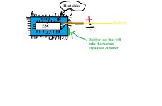
Just an idea that could be nice for cooling:
On the esc:
1: Put several small heat sinks wherever possible and use plastidip to cover the edges of the heat sinks and the rest of the esc. Plastidip can take temperatures up to 93 degree C. http://www.plastidip.com/home_solutions/Plasti_Dip
2: Put the esc which is now waterproof in the middle of a small waterproof metal container that has heat sinks around it. This container is filled with around 2 dl of water that covers the esc. Water has an excellent heat capacity and since its covering the whole esc it will transfer heat not only where the heatsinks on the esc are ,but everywhere. The plastidip rubber will of course not transfer heat very good but since the esc is covered in water it will be better than just exposed to air.
3.
Once I receive the new ESC PCBs with temperature sensors, I will log the temperature and currents while testing. I will also implement further current limiting when the heat is getting too high in order to make the ESC as bullet proof as possible.
If the temperatures can be logged then the esc can maybe be programmed to enter low lipo voltage slow cut off when the temperature is around 85 degree C. Avoiding melting of the plastidip.
4.If you want additional cooling you can sirculate the water with a small computer pump through a rc radiator. http://thescaleshop.webs.com/scaleradiators.htm

Yes it adds a whole lot to the complexity but if it would let me abuse my board going full trigger up and down steep hills with full brake it could be worth it. Meanwhile I am going to try the twin 300 A 16S alien: http://alienpowersystem.com/shop/car-esc/alien-300a-3-16s-car-esc-hv-twin/
 

Attachments

  • ESC for abuse.jpg
    ESC for abuse.jpg
    26.1 KB · Views: 1,947
makepeace said:
edit: looking at it now it's pretty complicated. and it actually takes quite a while. it does work though, and seems relatively accurate. if anyone has another method I would also love to know about it.

SDP-SI has models of their pulleys ready for download as STEP files; I just derive the geometry from there.
Been itching to make a truly parametric drive pulley model, though...

-

Anyways, hit me up if you happen to have any spare boards lying around. ;)
 
@Jan Christian
Sounds like a good idea, I will give it a try some time. However, so far, heating has not really been an issue. With the dual-motor longboard, I could go up even the longest and steepest hills with two ESCs in a closed box, without air circulation, without problems. With the single-motor 1:2 gearing setup, the 50mm motor was getting critically warm before the ESC. The big scorpion motor is the only one that managed to heat up the ESC when going uphill without getting too hot itself, but that was running at 8s with 60V FETs. The 40V FETs did not have heating problems at over 60A continuous uphill, but in that test the ESC was exposed to some air flow since I just taped it to the longboard. If you want to go fast up steep hills, I recommend a dual-motor setup unless you use a rather large single motor; and then you might need to add additional cooling to the ESC.
 
Back
Top