16-Parameter controllers don't 'speak the same language' as 5-Parameter LCD 3 displays?

EV_Ron

100 mW
Joined
Jul 31, 2014
Messages
46
Location
Jacksonville, FL
Background (questions below):
Last week, found burned R1, possibly FETs 1&2, 36V on a KU63/65 after 7 years and maybe 1000 miles. Death took about 4 days... Motor 1st cutting out after 20 minutes, then 10 minutes, 2 minutes then....just tick....tick. (Yes, will replace 100 Ω resistor once I find one... Wasn't there a place called Radio Shack??? :(

Needed a controller for testing so bought the only controller with connector for a display that I could get quickly (surprising how difficult/near impossible it is to find controllers sold alone that have a display cable. But, found Wal-Mart has a GREAT listing of controllers, better than eBay, Amazon, Sears, and Aliexpress combined, 100s of them! Check it out. I'm also now aware you can add a display cable to almost any controller because most have the signals on the PCB. Might be useful to someone.)

Anyway, bought an Ebikeling 36/48V 500W controller (yes, I know 22A capable) for use with 36V 10Ah batt, 2014 LCD 3 and Q100 (yes, I know 12-18A max by tinning the KU65 shunt.) I attempted to turn power down by setting C5=3, or so I thought; and therein lies the problem- that's BMSBattery C5, and ebikeling S830 LCD display manual doesn't even mention C settings 😲. So, their controller probably doesn't understand them.

Regardless, the ebikeling 500W controller drives the Q100 smoothly on throttle, both sensored & sensorless, and they even work in pedal assist... except PAS is set to 0 in the display (hmmm, 1st clue: PAS shouldn't work at all if PAS=0).

Here's the big clue that controller & display aren't communicating well: LCD 3 display shows 41V in lower right corner (which must be an AD measurement inside the LCD3 display), but MPH, battery icon charge level, W, and battery temp are all blank on the LCD3, and I assume all 4 are controller values 'transmitted' from the controller to the display. (Yes, I've checked pinouts: swapped 2 sensor pins in the Hall plug which made the Q100 run sensored, and everything else aligns.)

Questions:
Would someone please validate this logic & correct me of I'm wrong: the old LCD3 display and this new ebikeling 36/48 500W controller don't communicate well if at all because the LCD 3 display only knows parameters P1-5 (P5=15 of course being 36V voltage level) and the ebikeling controller expects an LCD 830 display and communicates P1-16, e.g. requiring "P03 the parameter to set Voltage Class: 24V /36V / 48V." (P3 for the LCD 3 is PAS mode, 0 or 1.)
And, they will never communicate correctly, right? (IOW, the KT LCD3 is not interchangeble with a the ebikeling LCD.)
Are ebikeling controllers made by KT?
Can you flash an LCD 3 to work with an ebikeling controller sp. its 16 parameters?
Does anyone do it (doesn't appear so, there's not a single post about it), or should I just fix/buy a KU65?
can you recommend another controller to replace the KU65 (I had a KU63/65 Type I=3 PAS levels).

Bottom line, I assume the new controller is defaulting to "48V battery" and therefore even 41V full charge is empty, which it "transmits" to the display, if any data is sent at all. Controller probably sends mph, temp, and power, too, but the 5-parameter KT LCD 3 doesn't understand the 16-parameter data stream.

Strange thing is, if I temporarily set P5 to 0 in the LCD 3, as others have done, battery shows full, as others have found.

Thanks

P.S.
I have searched battery icon blank, Ebikeling controllers etc, but nowhere did I find a mention about 16 parameter controllers, nor about differing parameter sets being a reason for non-communication, only incompatible displays & controllers. And, I've seen lots of discussion about flashing the LCD 3 to work with the TSDZ2 & Bafang MDM's internal controllers, but nothing about making it work with other controllers.
Yes, I've read as many of Amberwolf's posts on empty or half full battery symbols as I can, but nothing regarding parameters/ comms mismatch. I'm now starting to read casainho's posts on flashing the LCD 3, but I gather it's all in reference to the TSDZ2.
 
It is rare to find any compatibility

nothing to do with physical plugs.

Buy your display based on specific advice here, or from the controller vendor
 
Ebikeling 36/48V 500W Controller
https://ebikeling.com/products/ebikeling-electric-bicycle-controllers-small?_pos=4&_sid=ab7f0fc50&_ss=r

Display LCD 3
https://bmsbattery.com/parts/670-16454-s-lcd3-lcd-meter-for-s-series-controlers-ebike-kit.html#/137-color-black/484-connector_type-common_connector


E-HP said:
Post a link to the controller you purchased and the display.
 
So I searched: Does KT Kunteng make the S830 SW900 controllers?

This ad infers they're ALL made by KT.
48V 60A KT controller Brushless DC Motor Ebike Controller, KT-LCD8H LCD3 LCD8S LED900 Display One Set,for 2000W-3000W Kit
https://m.aliexpress.com/item/4000313241391.html

KT Website (we kind of knew this).
Suzhou KUNTENG Electronics Co., Ltd. is a specialized factory focusing on design, development, production and sale of electric vehicle controller, display instruments, sensors, corresponding products
http://www.szktdz.com/en/
Seems they have at least a 50% market share if not much higher.

So, same as at my company, there are probably ten or twenty hardware & software engineers sitting in a space together, all designing and programming similar but slightly different P parameter and C parameters and values for all their customers, with slightly different connectors. And they could probably make any one controller talk to a certain display. They're simply software and memory upgrades. I 'simply' want to know how to do it if possible.
 
I get it now, difference in comms is likely just the differing parameter sets.

Comparing my 2014 LCD3 P & C parameter lists to new S830 & SW900 P parameter sets, there's very high similarity. Some Shenzhen Kunteng engineering manager probably asked, "So, why do we have 2 parameter lists?"

Then he tasked an engineer to simplify and merge the P & C parameters into one P parameter list, obsoleting some old displays, and creating new sales opportunities. Now the question is, how do I access the new list via the old LCD3? For example, when controller asks for P03 (24V, 36V, 48V) convert and send P5. When controller sends Watts value place it in the W window.
Or...i could just buy the new display, even a $15 5-pin LED 880.

It's the same thing they did with adding one (yellow) wire to 4-pin LED 810s several years ago, they made them 5-pin 810s, 880s, & 890s...so they're minimally programmable and compatible with all 5-pin LCD wiring connector.
If three or four of the major motor companies motors often work with either LED or LCD 5-pin displays, then all of the 5-pin displays most likely share the same communications protocol. The difference, then, is the P & C parameters and the order in which they're sent& read.

FWIW, here's ebikeling list of P Parameters for SW900 & S830. All the ebike & kit companies publish virtually the same article.
https://ebikeling.com/blogs/news/how-to-set-sw900-lcd-display-parameters-ebikeling-ebike-conversion-kits

Hope that all helps someone besides me.
 
EV_Ron said:
Ebikeling 36/48V 500W Controller
https://ebikeling.com/products/ebikeling-electric-bicycle-controllers-small?_pos=4&_sid=ab7f0fc50&_ss=r

Display LCD 3
https://bmsbattery.com/parts/670-16454-s-lcd3-lcd-meter-for-s-series-controlers-ebike-kit.html#/137-color-black/484-connector_type-common_connector


E-HP said:
Post a link to the controller you purchased and the display.
Nope. Not going to work.
 
EV_Ron said:
Background (questions below):
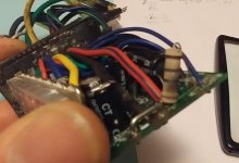
Last week, found burned R1, possibly FETs 1&2, 36V on a KU63/65 after 7 years and maybe 1000 miles. Death took about 4 days... Motor 1st cutting out after 20 minutes, then 10 minutes, 2 minutes then....just tick....tick. (Yes, will replace 100 Ω resistor once I find one... Wasn't there a place called Radio Shack??? :(

You used the controller to ride only 1000 miles in 7 years?

Why do you think R1 is burned? It should get very hot under normal usage, so it could look burned but be fine. Did you measure resistance in-circuit? Out of circuit?
 
Most of it was more recent. I was doing quite a few shorter sprints on the bike, smaller tool battery 4Ah, draining it further than I should have, so it's possible voltage sag caused higher current situations? Further, I noticed a tiny bit of white powder on the aluminum heat sink on the back side of the first 2 FETs. It's possible it was the heat sink conductive paste/pad....or, maybe the waterproof gasket allowed in a little moisture causing oxidation? The bike's never been outside in rain, but I know in the morning all metal here gets some condensation. I have not tested the FETs yet.

I have not measured R1 yet but it certainly looks discolored. I was very close to desoldering but wanted to test the motor first.
20211221_174925.jpg
I'll check the resistor now.
 
In circuit 67Ω.
Out of circuit 67Ω.
The rings appear Blk-blk-blk silver, but I believe it's supposed to be 100Ω, so 67 is 33% below that, well outside 10% tolerance. Don't know how it interacts with the circuit though.

When I said sprints, what I meant was near and at full throttle and pedaling hard too, not high speed.

Other than the wheel not turning, I found a post that stated, spin the drive wheel in reverse; if you get high resistance your FETs have failed / are failing. That's what I experienced when I tried spin my wheel on reverse. It never did it before.
 
EV_Ron said:
I'll check the resistor now.

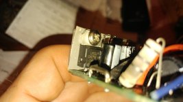
With the battery disconnected, you should be able to get a reading in-circuit. The discoloration looks normal for something that gets up to hundreds of degrees during normal operations. Is there an LM317 somewhere next to the MOSFETs? I'd test that. Connect the battery, power it on, and measure the output. It should be something like 15V.
 
Thanks? Any specific reason other than parameter misalignments?

I read a very good article showing how to sample the serial line to be able to view controller data in the eBIKE display, by ebikebuilder1. Similar 16 parameter output as noted above.
https://ebikeproject.wordpress.com/2017/10/28/controller-communication/

But...I'm not going down that rabbit hole. Ordered a refurbished SW900 & LED880 from ebikeling.

E-HP said:
EV_Ron said:
Ebikeling 36/48V 500W Controller
https://ebikeling.com/products/ebikeling-electric-bicycle-controllers-small?_pos=4&_sid=ab7f0fc50&_ss=r

Display LCD 3
https://bmsbattery.com/parts/670-16454-s-lcd3-lcd-meter-for-s-series-controlers-ebike-kit.html#/137-color-black/484-connector_type-common_connector


E-HP said:
Post a link to the controller you purchased and the display.
Nope. Not going to work.
 
LM317 output 0.26V immediately on activation, LED 810 as the display.

20211218_FET 7-different than other 6 LM317.jpg

Never testing voltage regulator before I don't know which legs to sample on the LM317 regardless, 2 pair are 0.26, outer pair 0.33V.
(Have analyzed and drawn out how the other 6 HY1607A's work to power motor windings, but not the LM.)

Tested again 1st pair 0.04V, 2d pair 0.51V, outer legs 0.58V. Doesn't seem like 15V... Guess that's bad?


Comrade said:
EV_Ron said:
I'll check the resistor now.

With the battery disconnected, you should be able to get a reading in-circuit. The discoloration looks normal for something that gets up to hundreds of degrees during normal operations. Is there an LM317 somewhere next to the MOSFETs? I'd test that. Connect the battery, power it on, and measure the output. It should be something like 15V.
 
Hmmm....at an output of 0.5V, the controller shouldn't work at all/ isn't working at all.

Replace the LM317? I might just have one of those.

5
.
.
minutes
.
.

later.

Nope. Only 5V regulators. Guess I need to get one.
 
What makes you say KT didn't make this one?

Searching around, it seems Shenzhen Kunteng makes a large percent of all small EV controllers as well all the LED 790, 810s, 880s, 890s, all the LCD 3, 5 6, 8, 830...& 900 displays.
Granted some are knockoffs, but likely the same board, SW, and often same /similar parameters.
But, I only did a 10 minute search to understand the market a bit.
Bafang displays look different, but some of their stuff came from KT and I'd bet some of the new stuff does, too.

Are there other manufacturers?

Thank you for checking those 2.

E-HP said:
EV_Ron said:
Thanks? Any specific reason other than parameter misalignments?

It's not a KT controller so it won't work with a KT display.
 
EV_Ron said:
Never testing voltage regulator before I don't know which legs to sample on the LM317 regardless, 2 pair are 0.26, outer pair 0.33V.

You'll easily be able to find a pinout online. It's a design that has been around for 50 years. Sounds like the LM317T is toast. You can take it out and test it on the bench.

I have a KT controller of similar design that I never installed, and had to fix the LM317T situation right out of the box. It had no heatsink and would kill itself very quickly. I'm pretty sure this Chinese design was on purpose. :roll:

You at least have it mounted to the common heatsink, but who knows just how counterfeit that ST LM317T is. It could be extra fake, so heat tolerance could be much worse than the spec sheet might suggest.
 
Thank you, doctor.

What is the proper title for R1, does it pass all the current coming back from the motor via the 2d FET?

Wait...

...checking Albert van Dalen's article on the KU63... https://avdweb.nl/solar-bike/electronics/ku63-motor-controller

"The resistor R1, which limits the dissipation of U1, has to be changed."

What's U1? Oh....it's the LM317T, according to the schematic.
https://avdweb.nl/Article_files/Solarbike/Motor-controller/China-BLDC-motor-controller-36V-250W.pdf

Why does a 15V voltage regulator handle so much current?? I thought it only powers the controller... does it handle all the current through the motor, too? No, but it provides the current to drive the gates of all 6 FETs.

Ok, I think I get it.? Does that sounds about right.

Funny, because I just watched an Irish guy and he said, "Don't know why all these controllers have a gigantic resistor that gets hot..." Video titled
Open Source KT Bike Controller with Regen
https://youtu.be/AevfY0HGgcs?t=5m02s
 
Oh, the LM317T goes to the 100Ω resistor then to U2. What's U2? A great rock band?
U2 is another VR, the 78L05, which sources 5V, 50mA. But why? The Irish guy says maybe it's to drop to 5V to provide the volttage regulators and provide for lights.

Guess I'll never be an EE.
 
Ahhh: one of Albert van Dalen's improvements:

"Redusing (sic) the LM78L05 dissipation:
The 5V current consumption is 50mA, which leads to a LM78L05 dissipation of 0.44W, this is close to the allowed maximum. There are known cases where the overheating of the LM78L05 caused failures. By mounting a 100Ω 1206 SMD resistor Rdiss between the 14V and the input of U2, the LM78L05 dissipation will be reduced."

Ok, call me confused. Like the Irish guy in the video, I don't see how the LM78L05 has to dissipate so much power. I'll stop. This is quite far off topic from
controller-display communications.

Y'all have a Happy New Year!
 
EV_Ron said:
U2 is another VR, the 78L05, which sources 5V, 50mA. But why? The Irish guy says maybe it's to drop to 5V to provide the volttage regulators and provide for lights

The first regulator (LM317) drops it from battery voltage to 15V, and that drives the gates on the MOSFETs, then that ~15V gets dropped again to 5V by the second regulator (78L05). 5V has been around for ages and is a common logic level voltage. That powers the CPU chip, the hall sensors, etc.

The reason for the big resistors is to drop voltage before it hits the LM317. If not for that resistor it would go up in smoke within minutes. But since the resistor can run much hotter, they use that. LM317 is a linear regulator so it's just as inefficient as dropping voltage with a resistor.

It's a very strange approach to power these motor controllers. There is nothing wrong with the design if you don't care about wasted energy (but you do on a battery powered device) and there is nothing wrong with it if it's designed with ample headroom (but it isn't, things are running at the limits).

I have very strong suspicions that that's how the Chinese built in planned obsolescence into these things. They wanted these components to run hot and fail after a season of riding, if that.
 
Great learning opportunity, Comrade.

The Irish guy in the video I linked did say about the resistor, "it's probably just a cheap and reliable way of dropping the voltage to the voltage regulators." You validated and clarified his assumption.

Thanks for filling in the holes!

Happy New Year.
 
EV_Ron said:
The Irish guy in the video

I literally have an identical controller as that guy.

It has an ST LM317T with a max operating temperature of 125c. It got up to 142c in a cold room (65F) with the case open. Just imagine how hot it would be in the summer under load.

It's supposed to have thermal protection and thermal rollback but it's likely a counterfeit ST component. Which is probably a good thing because if it rolled back output to stay cool, the MOSFETs would not be driven as hard, which would make them overheat. And that would start a chain reaction. Inside of the controller case would get even hotter, the LM317T would cut back even more, the MOSFETs get even hotter, and so on.

Very blatant planned obsolescence.

hot_lm317t.jpg
 
What makes you say KT didn't make this one?

...

Are there other manufacturers?

We are talking China, likely even outside Shenzhen there are hundreds.

And this "planned obsolescence" idea is giving far too much credit. Yes they are allergic to the concept of quality

But the motivation is simply to shave 6.37056 CNY off the manufacturing cost
 
EV_Ron said:
What makes you say KT didn't make this one?
Seems moot now, since it looks like you're headed down a better path now, taking john61ct's advice. :bigthumb:

john61ct said:
Buy your display based on specific advice here, or from the controller vendor

EV_Ron said:
But...I'm not going down that rabbit hole. Ordered a refurbished SW900 & LED880 from ebikeling.
 
Back
Top