1989 Kawasaki EX500 (Ninja) - Second build, slow and steady

By the way, the nickel I had any luck with was 0.15 mm. 0.20 mm was too thick, at least for the Sunkko anyway. Hope it works out for you!
 
By the way, the nickel I had any luck with was 0.15 mm. 0.20 mm was too thick, at least for the Sunkko anyway. Hope it works out for you!
Once I added the second transformer, I had no problem with .2mm nickel + the thin copper tape you suggested. Need to fine tune the settings, but I made several good connections on scrap cells. Tearing them off tore thee nickel before it tore the weld
 
Electrical question. For the terminal ends of the packs that I'll be spot welding. I will pre-solder a piece of 14awg with a ring terminal connector to a section of nickel strip, which will then get spot welded to the cells at the ends of the pack. The ring terminal then can get screwed into my terminal busbars.

Inspiration taken from James Biggar, skip to 8:09 for the general idea of what I'm planning:
I prefer this method because of the mechanical connection from the packs to the busbar, instead of a soldered or spot welded connection.

Unfortunately, I have 30p packs, and I'm making two of them, so each end needs a busbar. That's 120 holes in 3.5mm thick copper. Can I bolt 2ea wires into a single hole, basically stacking two ring terminals with each bolt? That would be half as many holes and half as much drilling. Or does each cell need to terminate to the busbar on its own? I guess I'm worried that stacking two small ring terminals, each one carrying 10amps, might create a hot spot. So i realize I'm basically answering my own question, that each series connection needs to have it's own terminal. But I'm curious what others think.
 
Eh, I decided to give each series wire its own spot on the busbar. Not worth a hotspot or potentially higher resistance later just because I'm trying to avoid work now. I'm designing pieces of plastic that will hold captured nuts and get fastened to the sides of the pack. They'll do double duty, both creating the mechanical connection point for the ring terminals, and securing the busbar itself to the sides of the packs.
 
FWIW, I feel for you; I am about to rebuild one of my 28-cell EIG packs for the lawnmower from a 14s2p to a 28s1p, and I only have 2p busbars...so I have to take the braid off some old RG75 cable, cut it into 3" lengths, and crimp that into two eyelets each to bolt each cell to the next.

Or, flatten the braid out and solder the ends, then drill them to directly bolt to the cells...

Nothing like the amount of connections you've got to deal with, but I'm not looking forward to it. (but when I'm done the pack will be half the weight so the mower will be a lot easier to use).
At least I just have to make through-holes in the busbars, because the plastic mounts behind the busbars will have the nut to grab onto each screw. I won't have to individually tap and thread 120 holes, like it did in the above video. Also, I wasn't sure about the longevity of copper threads anyway.
 
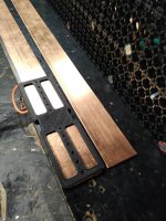
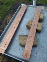
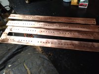
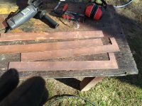
Made busbars today. Got some 4ft lengths of something for the scrapyard, all 4 for $100, and I'm only using 1, so $25. I was estimating in the range of $200-300 if I had to make them from newly purchased copper bar stock.
IMG_20240409_095921.jpg

One side of each 14s pack gets a short tab left on it to connect it to the one sitting next to it:
IMG_20240409_102650.jpg
Using a printed stencil to drill 30 holes in each one, one for each cell in the parallel group:
IMG_20240409_133214.jpg

IMG_20240409_145543.jpg
Predrill a small hole, then a stepped bit to get the final size. Plus larger bolt holes at the end for pack connections. And voila! That was a ton of work, but it should pay off in performance and pack assembly.
IMG_20240409_155558.jpg
 
whatever you used to cut those, when you are done, would ya mind dropping by? I have a bugger of a time cutting a straight line longer than the 12" guillotine blade on my cutter....
 
whatever you used to cut those, when you are done, would ya mind dropping by? I have a bugger of a time cutting a straight line longer than the 12" guillotine blade on my cutter....
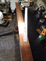
Just and angle grinder with a cutoff wheel, by hand. I designed and printed a centerpoint finder first. Since wherever the piece of copper came from was factory produced, it had an outside width of 109mm all the way down. My print simply bracketed the long piece with a hole in the exact center, and I used that to scratch a line with a scribe (you can kind of see it in the first pic).

Then I just needed to cut it by hand nice and straight. Shallow first pass to make a groove, and deeper passes tend to follow the first groove.
 
Can someone double check my ampacity esimation? On the battery pack, on the cells on the end, a single short length of wire will be going from each cell to the busbar, and connecting to the busbar via a ring terminal. Only about 1.5 inches max, and it needs to make a rough 90 degreed bend. I had originally planned on 14awg. I just tried it out, and it's too stiff for such a short length.

I have lots of 18awg that I can use. Is that going to work? Each cell is capable of 10A continuous, so each 1.5inch length of wire needs to be able to carry the same 10A, with minimal or no voltage sag. Various ampacity charts differ on how many amps wire can carry. If you use Matador's chart, which a lot of people on the forum seem to use, it suggests that 18awg copper can conservatively handle 14-15 amps. So it seems like 18awg stranded copper should work...

Or am I going to need to purchase some 16awg, which I do not currently have on hand?
If the bend radius is your restriction you could just double up the 18AWG to be equivalent to 16AWG or triple it to get close to the 14AWG you intended to use. It is quite common to see double/triple wire connections on compact speed controllers like VESC. With the wires terminating into such hefty busbars I'm confident heating won't be an issue, likewise for voltage drop which would be neligible on such a short run.
It think 2 x 18AWG would be sufficient. 18AWG is only .82mm2 for a total of 24.5mm2 across the 30P connection. Not quite enough for 300A continous although you won't be able to use the 300A for more than a minute or two at a time.
 
Last edited:
If the bend radius is your restriction you could just double up the 18AWG to be equivalent to 16AWG or triple it to get close to the 14AWG you intended to use. It is quite common to see double/triple wire connections on compact speed controllers like VESC. With the wires terminating into such hefty busbars I'm confident heating won't be an issue, likewise for voltage drop which would be neligible on such a short run.
It think 2 x 18AWG would be sufficient. 18AWG is only .82mm2 for a total of 24.5mm2 across the 30P connection. Not quite enough for 300A continous although you won't be able to use the 300A for more than a minute or two at a time.
Thank you, appreciate your input. I was considering doubling up 18awg as well, and decided not to for two reasons. First was labor: I need to premake and presolder 120 of these connections, which will be nickel strip soldered to wire, other end of wire with a ring terminal. It's going to be finicky work as it is, stripping two ends of tiny 1.5inch wires 120 times, and I didn't want to make it 240 times, or 360 times. Second was aesthetics, as my battery will be visible through clear polycarbonate. While I do have a bunch of 18awg, it would have been several different colors.

So I broke down and bought a roll of 16awg that would be more than enough for my project. It wasn't expensive at $12, especially in the grand scheme of an entire motorcycle build, but it was certainly a moral defeat, as I make a point of using salvaged wire and cabling in all my projects. I get plenty for either free, or a tiny percentage of what new copper cabling would be.

Anyway, 16awg at about 1.5mm2 each, times 30 connections, gives me about 45mm2 for 300 amps, which should be enough for short bursts. At that point I'm limited by the cells, and the copper won't be heating up at all.
 
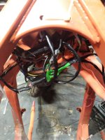
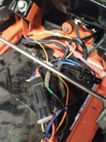
One of these days I will make an electric motorcycle. And when I do, I will make a wiring harness for it. All of the wires will be exactly the same length. All the wiring paths will be tidy, with no excess slack at the ends. One day, I will successfully plan a harness that will have all of the connections tidy and we'll organized, and there will be no huge tangle of various connectors that I have to ball up and hide somewhere. One day...
IMG_20240421_164157.jpgIMG_20240421_164208.jpg

But today is not that day. Now hand me that pack of zip ties and don't look under the tank.
 
And when I do, I will make a wiring harness for it. All of the wires will be exactly the same length. All the wiring paths will be tidy, with no excess slack at the ends. One day, I will successfully plan a harness that will have all of the connections tidy and we'll organized, and there will be no huge tangle of various connectors that I have to ball up and hide somewhere. One day...
I did that for the SB Cruiser...but then I kept experimenting, and eventually, well....
 
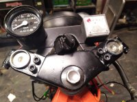
Here's my first draft for a riding display, any suggestions? Printing is cheap, I can change this around as many times as I want.
IMG_20240426_144043.jpg

Debating whether to have a windshield-like raised faring in the front, even a little one. It'd make it look more sportbike-like. Or to leave the gauges hanging out as they are, more like a classic cruiser style.
 
Back
Top