1989 Kawasaki EX500 (Ninja) - Second build, slow and steady

I think you will be fine with drilling the frame, but try to keep the holes small. If you go with 12.9 grade bolts this will give you plenty of strength. Considering that you can get thinner bolt since 12.9 grade has a very high tensile strength. Really in efforts to keep the hole small in the frame. I would go with 5 bolts like in the picture. think it’s important to put a bolt in that back corner. If you can find some large washers (for the top) almost as big as the width of the frame rails, that would help spread out the load over a larger surface area. I would go with 12.9 grade washers as well.
Going with M10 would be even stronger but I would go with M8 to try to keep the hole smaller as long as you stick with the strong 12.9 grade steel.

12.9 grade bolts

Locking nut


762F45E6-339B-400A-BF75-11814E2A48E7.jpeg
 
When drilling into frame rails, going into the flange on the vertical plan has the most stress. Drilling on the horizontal plane, not so much. I was taught that in frame rails you drill the hole and then ream it to size. That lowers the stress risers in the hole. Big washers, or a u thingee on the top sure would help in carrying the vertical load, and that would be the shock load of the weight of the batteries.
 
Thanks everyone for your input. I also spoke with a welder, the guy who made the battery case for my last build, who builds custom motorcycle and dragster frames for a living. He was the one who first pointed out to me that my last conversion used a stressed member engine and he made the battery case to accommodate that. So I trust his judgement pretty well. He said that while of course you dont want to drill holes in a frame everywhere, my specific case shouldn't affect it structurally, especially since the battery isn't actually that have l heavy, the bike wont be going faster than 70mph, and I'm not taking it off road.

@Eastwood , your suggested bolt locations are exactly what I had planned as well, with 2 on one side and 3 on the other. Washers are definitely a good idea as well.


I was taught that in frame rails you drill the hole and then ream it to size.
Would you then suggest I drill a small hole to start, then switch to a stepped bit too achieve the final size? I'm also planning on 3d printing a guide to get the holes centered on the tube and as perpendicular as possible.
 
You drill the hole slightly undersized and then use a reamer for your finished hole size. The size of drill used is matched to the reamer. Your're just shaving some metal to reach your finished hole size. This limits any potential stress riser that may occur in the metal from the more violent action of the twist drill.
 
Alright, thanks everyone for the advice, including my local welder that helped me out. Went quite a bit easier than I thought, holes are nice and tight with no wiggle in either the frame or the plate.

Started with 3d printing a guide/jig thing that would ensure my pilot hole was centered on the tube and perpendicular.
IMG_20240202_121613.jpg
After 5 pilot holes in the frame were drilled, I clamped on my bottom plate, then used the frame holes to pilot hole the plate
IMG_20240202_122042.jpg
Then used @gromike 's suggestion and used a ream drill bit (my local hardware store had them) on both the frame and the bottom plate. Was very pleased to see the bolts went straight through with zero issues. @Eastwood , my local hardware store luckily had their own Grade 12.9 M8 bolts. Not 12.9 nuts unfortunately, but I just grabbed some basic M8 nuts for now and I'll order the higher strength nuts for later.
IMG_20240202_152341.jpgIMG_20240202_152349.jpg

The 5th nut in the back is at an angle to the plate, so I'm printing an angled spacer to fill that gap. Once I have a design that fits, I can use the 3d printed spacer as a stencil to fab one out of a hunk of metal by eye/hand.
IMG_20240202_152419.jpg

And I realized there's some frame holes on the back that I could use for some extra support, so I made an angled bracket out of scrap steel to help with the load a bit.
IMG_20240202_162852.jpgIMG_20240202_162858.jpg

Now that that's done, I can basically do whatever I want with a battery case, and just sit it on the plate, with supplementary supports on the top end. Surely there's more elegant, less bulky solutions out there, for those of you who are more talented at fabrication than I am. But for me, having this huge metal plate that can accommodate whatever battery shape I end up with really takes the pressure off my eventual battery design and construction. And I still don't know how to weld, I'll have to learn eventually, so this saved me a few hundred bucks from paying for a welder to fabricate something for me like I did on the last conversion.
 
Fun little modification. I was thinking about charging, and currently when I plug in my 72v nominal pack, without precharging, I get a big spark. The spark will be even bigger on my 28s battery. Wanted a more elegant solution for this build, and one that was built into the bike itself, rather than the charger or the plug. I'm going to order a couple more of those contactors on BatteryHookup, they're only $15 now, and place it on the positive side of the charging port. It's built for 900vdc, so a 120v spark should be no problem for it on a regular basis. That way, when I plug in a charger, the charging circuit won't be closed until the contactor is closed. Now for triggering the relay:

I had purchased a generic keyed ignition awhile ago, one that fit the mounting points already on the bike (it was this one). It was simple, just has a NO switch. Also has a frame lock in the counterclockwise position, which I wasn't going to use. However, behind that metal plate was a plastic slider that moves laterally to engage that frame lock pin.
IMG_20240216_140000.jpg
IMG_20240216_135950.jpg

So I drew and printed a replacement for that metal plate, one which would hold a microswitch that would close the contacts when the frame lock was engaged
IMG_20240217_085302.jpgIMG_20240217_085330.jpg

I can use this microswitch to engage the coil on the contactor. Not only do I not need to find a placement for a separate switch somewhere on the bike, but by incorporating it into the ignition, it acts as an added safety, like an interlock: I can't charge the bike while the controller is in the on position, nor can I turn on the bike and run it while its charging. Plus I'm a fan of a simple, analog, human-operated spark reduction (I know it's not technically precharge, since there's still a spark, but it at least moves the spark away from my hands and the charging port, into a space that is designed for it).

Just wanted to share in case someone else wanted to use this idea for charging or spark reduction on their build.
 
New member here and really enjoyed catching up on your project!

My bike has a switch on battery I can eliminate spark with. I'm building a mini ATV and using switch below alongside new master fuse. I'll link below reference pic. Handles 455a and no scary sparks or noises. When I have cover off, I simply use same connector pigtailed to HD male/female spades. I let those spade connectors arc instead of the connector.

Keep up the awesome work 😎
1000012597.jpg

 
Hey I also just realized that with that last modification, there's an added safety benefit. My charging port, a big Anderson SB50, is built into the former gas cap on the top. And it has fairly large and exposed contacts. Sure I've printed a cover for it, but still, potentially 120v exposed contacts when I go to plug in the bike or disconnect the charger. Now, the contacts won't be live until the key is in the charge position. Extra safety! Wasn't even planning that, just a happy coincidence.
 
I've basically determined that I'll be using my QS273 8000w hub motor for this build, the one that I'm currently riding on. Since that's decided, I can get to work on modifying the swingarm to accept a hub motor. Which means torque arms! I'm not even going to mention how embarrassed I am of my current build and how the motor is secured, I have learned a lot in 2 years and I'll be going with something more secure this time around.

The EX500 swingarm has nice square recesses around the axle holes, like many other Japanese motorcycles I've seen from this era. Keeping it simple and straightforward then, with minimal cutting and drilling to the steel: I need a square chunk of metal to fit into that recess from which I can fashion clamping style dropouts.
IMG_20240308_140413.jpg

Started with a 3D printed stencil of my plan:
IMG_20240308_140443.jpg

I'll just need to open up the back of the swingarm to slide in the hub motor, and a single drilled M8 hole through the flat face to keep it from sliding out the back. My prototype is also incorporating those stock torque arms that QSMotor sends you, the ones that are far too loose to work as a torque arm on their own, but still function well enough as a washer, spacer, and/or added insurance against the motor slipping off the swingarm.

I got real lucky on my trip to the scrapyard today and found some 20mm thick aluminum scraps that must have been off cuts or discards from a machine shop.
IMG_20240308_140505.jpg

Because you see that the scraps already have several holes tapped with M8x1.25, exactly centered. Thanks for doing half of the work for me, scrapyard fairy! I just need to line up my stencil to incorporate the already-tapped holes:
IMG_20240308_140622.jpg


And got to work with a hacksaw, angle grinder, drill press, ect.
IMG_20240308_142654.jpgIMG_20240308_145901.jpgIMG_20240308_163050.jpg

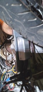
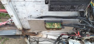
Not pretty, but it should do the job quite well, I kept the tolerances as close as I could to minimize wiggle. I'm still riding on the motor, but I 3d printed a copy of the axle to test fitment (which is M18 flatted to 14mm on two sides, for anyone who needs the info). That way I can get the swingarm all ready for the motor, so when it comes time to swap the parts over, I shouldn't have to waste too much time fabricating.

IMG_20240308_173500.jpgIMG_20240308_173515.jpg

So the torque arms are held in place by the M8 bolt hole going through the stock QS torque arms, then the swing arm, then the toque arm. As well as being held in place vertically by the top and bottom pieces of metal from the swingarm. And of course the axle's nut on top of everything (not pictured cuz it's just a printed mockup for now). The axle will have 20mm of metal clamping it down. I know it's aluminum, but it's 20mm, and I can always find a local machinist later who might be willing to remake them for me out of mild steel. But it's certainly way better than what I'm riding on now!

One question. I've browsed the torque arm picture thread. Do I need to cut a stress relief line?
IMG_20240308_173949.jpg

Like on the bottom. I've seen it on some, but not all of the DIY torque arms I've seen. Which is going to be better? I don't mind remaking another one, I still have plenty extra metal that I can use if I need to.
 
Instead of cutting the backend of the swing arm off clean,
I cut a slot out of the bottom back part of the axle slot, the size of the flat part of axle
That way the axle goes up into the slot,from underneath with weight on the bike the axle cannot slide out the backend. added insurance
 
Instead of cutting the backend of the swing arm off clean,
I cut a slot out of the bottom back part of the axle slot, the size of the flat part of axle
That way the axle goes up into the slot,from underneath with weight on the bike the axle cannot slide out the backend. added insurance
Ah, that's a good idea. I'll remember that for next time.

Alternatively, the nice thing about converting older, common model motorcycles is that I could always purchase another swingarm from eBay
 
If I had another I would have something like what you made welded to the inside on each side,
That way it is a shorter span for the axle
Now I just use spacers
 
Also decided to go with the same cells I used on my moped conversion, from BatteryClearingHouse. These are LG MH1 cells, from low-volt recovered rideshare scooters, 10A continuous discharge (with appreciable sag), 3200 mah rated, $0.70 per cell shipped. I'll be making them as 2ea 14s packs in series, both for ease of construction/installation, and also for future second-life use in my home's DIY powerwall, which is also 14s. Or third-life use, since these are already reclaimed cells. I should be able to fit 28s30p, meaning it'll be in the range of 9.5kwh, which is kinda huge, could give 80+ miles of range (on paper anyway). And 10A max discharge, times 30p, nominal 102v, means the pack should be capable of 30kw max discharge. That's way overkill, which is good, because I doubt I'll be seeing more than 15kw with my use. And good because even though the cells are rated to go down to 2.5v @ 10A (i tested them myself), they are going to experience noticeable voltage sag. I'm okay with it, the pros outweigh the cons in my use case. Basically I'm going to be making a Tesla-inspired battery: a ridiculous number of mediocre-discharge 18650s for max range that won't do well in the winter!

Ordered 16 scooter packs, to give me 832 cells. That plus the 112 cells leftover from my previous build gives me the 840 I need for 28s30p, plus extra if some test well.
IMG_20240301_145804.jpg

These packs nicely break down into 3s units which are much safer and easier to disassemble
IMG_20240301_171523.jpg

Then nickel strip comes off, and cells get rewrapped to check for damage, rust, ect.
IMG_20240303_154732.jpg

These need to be recovered from low voltage state slowly and carefully, and then individually tested, so it'll take 1-2 months as a background project. But now that the battery is decided, that's the last major component for the motorcycle, so it's looking like the bike might actually be in some sort of completed state by the end of this year. Cool.
 
Made a small aluminum tray from scrap pieces to go under the seat and hold some components: 2 contactors and a service breaker/disconnect. First CAD (cardboard-aided design, my favorite in-joke that I saw elsewhere on this forum):
IMG_20240309_145211.jpg
IMG_20240309_151925.jpg

Quick coat of pain, nothing fancy. Also using a series of rubber washers to electrically isolate the tray from the bike's frame, in case of catastrophe. I don't imagine any of those bolts getting loose, but you never know, better safe than sorry.
IMG_20240312_161702.jpgIMG_20240312_163327.jpg

And a simple cover to keep the exposed contacts shielded from errant fingers if I need to remove the seat. Please ignore the gross layer lines, I was having calibration issues.
IMG_20240312_163355.jpg


Also got the cell holders in and I wanted to triple check that my planned battery will fit under the tank. And yeah, it will, but holy crap. Now that it's in front of me, this is gonna be a huge pack! I only mocked up one of the two 14s sections to check height for now.

IMG_20240312_170249.jpgIMG_20240312_170221.jpg
 
Looking for advice and opinions on exact controller mounting position.

The controller is going to go where the radiator was, behind the front wheel and in front of the battery. I made a 3mm aluminum plate to go behind the wheel and use the bike's already exiting mounting points. (sorry for blurry pictures)
IMG_20240316_104200.jpg

Option 1: I can put the controller in front of the plate facing the wheel. This will get the best airflow for active cooling. Downsides: it's gonna pick up a bunch of dirt and debris, especially in the slots in the aluminum casing. There's also increased chance of high speed larger debris taking chunks out of the casing. It's built rather tough, but nothing is invulnerable.

(In the following pic, the chunks of pink Styrofoam represent the controller)
IMG_20240316_104649.jpg
To me there appears to be plenty of clearance for suspension travel on the front wheel.

Option 2: there's enough room, if I use some spacers, to mount the controller on the opposite side, facing the battery. It'll basically be right up against the plexiglass, with no more than 5-10mm clearance in some spots.
IMG_20240316_104250.jpg
Upsides, it's going to get lots more physical protection, while still having decent airflow for cooling. Downsides, it seems like it might look rather crowded, aesthetically; shoved up right next to the battery, at a different angle

Which position should I go with? The nice thing is that the controller's mounting holes are mirrored, so it would be very little effort to switch back and forth, using the same mounting holes.
 
How hot do you expect it to get? ;)

if the controller's mounting points are intended to bolt it to a heatsink, then even having it bolted to the "back" of that plate, assuming you have good flat contact with the plate vs controller along the whole surface area, will let it shed heat as well or even better with the controller out of the way of the airflow onto the plate.

If the plate isn't really flat to the controller mounting face, and there's air gaps anywher,e then those areas won't transfer heat well and it that's the majority of the interface, then if the entire controller shell is a heatsink it's probably going to shed heat better on the front face of the plate.


This is how I mounted the Phaserunners on the bottom of the trike, using some aluminum I had laying around--the v6 is on an old rack ear/handle mount, probably 3/16" thick, and the v1 is on a 1/4" thick plate saved long ago from the inside of some old rackmount test equipment that I don't even remember what it was. (been using it as a clamping plate now and then for various assembly operations) Note that the v6 is actualy bolted to it's plate, but the v1 is only ziptied (with I think one mounting bolt, as I didn't have any more with the right thread and enough length).

I don't push them hard for more than a few seconds at a time, but I do that frequently on my commutes. This way they will never ;) build up heat since air flowing under the trike can help cool the plates off. (conversely the very hot pavement in summer may induce heat into the plates and controllers while sitting in unmoving air at traffic controls, but that was also true of all the plain old controllers I've ever had bolted to the bottom of the trike, like the grinfineon still visible in the PRv1 pic below)
 

Attachments

  • 20231001_190927.jpg
    20231001_190927.jpg
    894.3 KB · Views: 6
  • 20240226_122403.jpg
    20240226_122403.jpg
    4 MB · Views: 7
I vote for the controller on the inside of the plate. For a few reasons, First, it’ll look cleaner not seeing the controller and the wires coming out from it. Then, like you mentioned, dirt and debris would cover the controller if it was on the outside of the plate, not to mention water, which is the biggest hurdle.

Just an idea, you could cover up that gap by simply cutting some ABS plastic and piecing it in there. Would probably help debris or anything else coming around the side of the plate, keeping it off the controller.
IMG_0043.jpeg
You could also cover that gap with the extra aluminum you have doing that through aluminum brazing, all you need is a torch and some aluminum brazing rods.

Then to AmberWolf point, even if your controller already has a heat sink by connecting it to more metal it’s gonna help cool it even more. So yeah, if the controller goes on the inside and it is mounted flush to that aluminum plate, the airflow hitting the outside of the plate would also help cool the controller if you have a great surface contact between the controller and aluminum plate. Some thermal paste would help with that as well. You can always sand the back of that aluminum plate up against an old piece of glass or mirror with sandpaper between to somewhat machine It completely flat. You can do the same with the controller mounting side.
 
Last edited:
I vote for the controller on the inside of the plate. For a few reasons, First, it’ll look cleaner not seeing the controller and the wires coming out from it. Then, like you mentioned, dirt and debris would cover the controller if it was on the outside of the plate, not to mention water, which is the biggest hurdle.

Just an idea, you could cover up that gap by simply cutting some ABS plastic and piecing it in there. Would probably help debris or anything else coming around the side of the plate, keeping it off the controller.
View attachment 349280
You could also cover that gap with the extra aluminum you have doing that through aluminum brazing, all you need is a torch and some aluminum brazing rods.

Then to AmberWolf point, even if your controller already has a heat sink by connecting it to more metal it’s gonna help cool it even more. So yeah, if the controller goes on the inside and it is mounted flush to that aluminum plate, the airflow hitting the outside of the plate would also help cool the controller if you have a great surface contact between the controller and aluminum plate. Some thermal paste would help with that as well. You can always sand the back of that aluminum plate up against an old piece of glass or mirror with sandpaper between to somewhat machine It completely flat. You can do the same with the controller mounting side.
Thanks for your input, I was also leaning towards interior placement.

You and I have different aesthetic choices, though!
First, it’ll look cleaner not seeing the controller and the wires coming out from it.
you could cover up that gap by simply cutting some ABS plastic and piecing it in there.
I actually don't mind the gap itself, and the whole look of the bike is going to be "exposed" wire. I'll be using a bunch of nice fabric orange wire wrap on everything, no farings, clear polycarbonate battery case... I want the aesthetic to be: "it's stupidly obvious that this is a DIY electric motorcycle conversion"

But as for wires coming in/out of the controller, especially the battery cables, you won't want exposed conduit. I've been working on 3d printing caps and covers for all those exposed lugs, so that there won't be accidental touching. So for me, exposed cables and wires = cool looking, exposed contacts = no bueno.
 
You and I have different aesthetic choices, though!

OK gotcha 👍


I actually don't mind the gap itself, and the whole look of the bike is going to be "exposed" wire. I'll be using a bunch of nice fabric orange wire wrap on everything, no farings, clear polycarbonate battery case... I want the aesthetic to be: "it's stupidly obvious that this is a DIY electric motorcycle conversion"

But as for wires coming in/out of the controller, especially the battery cables, you won't want exposed conduit. I've been working on 3d printing caps and covers for all those exposed lugs, so that there won't be accidental touching. So for me, exposed cables and wires = cool looking, exposed contacts = no bueno.

What controller are you running?
I like the way you mounted your contactors on that plate 👍
what fuse did you use for your DC step down? I remember a while back you had issues with the step down on the other build.
 
What controller are you running?
APT 96600, one I got from QSmotors with the hub motor. I think that perhaps its not the best controller if you want max performance or if you like control of every singe setting. But I don't care about either of those things, and I like that it's an oversized big hunk of tech. I have yet to have a major issue with it yet, knock on wood.
I like the way you mounted your contactors on that plate 👍
Thank you
what fuse did you use for your DC step down? I remember a while back you had issues with the step down on the other build.
I've fused it on both input and output, not sure if that's correct practice, but it makes my brain happy. Since it'll be 120v to 12v, and I only need about 5-8amps at 12v... I got a 20 amp rated converter. So, 240w. Therefore, I've put a 2amp fuse on the input, and a 15 amp fuse on the output.

Funny you remember my converter issues earlier. However, my best guess from why I killed two of them isn't due to amperage, but voltage. I theorized at the time that the cause was a 100% fully charge battery, on which I pulled out of the driveway and braked with a little bit of regen. The BMS cutoff to protect the cells from overvoltage, therefore the controller attempted to direct regen to the only thing it was still attached to, which was the converter. Treating the converter as a battery/load essentially dumped as much voltage into the converter as it could on its input side. Since there was no "load" i theorized that the input was exposed to high voltage with no way to absorb it, and whatever capacitors/fets/other components received a way higher voltage than their rating.

I haven't killed any other converters since then, maybe because I've been careful about regen with a full battery. Though to address the potential reoccurance on this build, I've done two things. First, I simply ordered 2 converters right off the bat, so I'll be able to immediately have the spare part available if one dies. Second, I ordered converters that are rated for 150v input, when my battery will max out at 120v. Hopefully I won't see this issue happen again.
 
I'm nearing the end of the testing of 832 individual cell. Very arduous, even though I like the process, started to drag on. Therefore I started to look to the actual assembly. I have a spot welder that I made a few years ago, from a microwave oven transformer and one of those cheap Chinesium timing boards. I know the consensus on the forum is that they're okay, but MOT spot welders aren't strong enough to weld nickel thick enough for high current applications. Yet I was stubborn, and I didn't want to purchase a different product. It successfully welded over a thousand cells for my house's powerwall, it welded all the LFP cells for my current motorcycle, it was even able to do nickel-plated steel plus thin copper for my current moped...

For this build, however, I'm gonna need .2mm pure nickel, plus copper tape (thanks again @jonescg !), for the series connections. And no matter how much I tweaked with the settings, it was just too much materiel for the little spot welder that could, I couldn't get reliable welds on any test cells.
Then I had an obvious idea that I'm annoyed I didn't think of years ago. You know what's better than a spot welder made from a microwave transformer? A spot welder made from two microwave transformers!
IMG_20240401_133545.jpg
Same control board. All you need to do is parallel the primary coils, and you can series the thick windings of the secondary coil. That way you can you crazy thick cable for high amps, but have a bit more voltage to get it down the leads too. Mad that I didn't think of it earlier, so easy, but maybe someone else reading the forum will learn from my mistakes.

Also took the opportunity to print a housing for the electrodes, that also holds the trigger switch. So I only need one hand to weld, other hand can stabilize the nickel strips. Once I had two transformers wired up, it took no time at all to get very secure, clean welds onto a cell, barely even warmed up the can.
IMG_20240401_140950.jpg
 
Finally got enough pieces together to see if my plan for the battery case will actually fit. And it does! Very pleased I don't have to redesign. Everybody else on the forum seems to have much better CAD and design skills than I do, all I could go on was dummy estimations of what I think would fit and hoping I was right.
IMG_20240402_085854.jpg
The sides are 1/4" polycarbonate sheets. They slot into a sort of holster in the bottom, which is also a "footprint" that will perfectly capture my 2ea 14s packs (with padding for vibration protection). The black lid mirrors the footprint, again capturing both the 4 sides of the box as well as the 2 battery packs. It also incorporates a slot for the BMS, and tabs that will be the main positive and negative busbars, where you can see the orange covers to prevent accidental shorting.

Hard to see in the picture, but I will also have 10mm steel bars in the front and the rear of the PC sheets, which use the bike's original engine mounting points and will use brackets to fasten the front and rear PC sheets themselves. For the top, I'm gonna keep it simple and use ratchet straps to hold the lid and the top of the battery down and further keep it from bouncing out of the bike. It'll be hidden by the tank anyway:
IMG_20240402_090340.jpgIMG_20240402_090349.jpg

Got reeeeaaally close on the frame on one spot but it clears
IMG_20240402_085817.jpg
 
Back
Top