40T, neodymium magnets, plasti dip cycle test

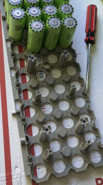
Once you get tons of shock and vibration in play

those copper edges would IMO risk scraping through the wrap and making contact with the cylinder wall "shoulders"

I know with A123 that is positive, but even on cells where it is negative that would create problems
 
i agree, sharp edge is no good but like Hummina mentioned, if the copper was stamped like nickel strip you could trim out the positive parallel connection and just use those cell insulator rings that most people use
 
As it is now with the sharp corners and no protective rings its going to be considered unsafe by I think everyone and for good reason. Surely u could just trim the copper back just w some snips. Or maybe when it shorts the cells will be high enough power to vaporize the copper and blow through it.

What’s a cheap easy way to stamp/cut the copper? How thick is it? .2mm stuff is pretty adequate for most things I think. Maybe two machined steel parts and an arbor press be good enough as copper is so soft?

Or maybe could get a bunch of stickers made on a laser cutter or a mill and use them with acid? That might be a toxic mess.

Clamping multiple copper sheet down on a cnc mill maybe would work and be simplest but require some good clamping.
 
Shadeebas press idea sounds best nice and clean quick turn around.

Coppers soft and thin enough to press in a vice jaws if need be.
 
etching need not be as poisonous as i thought but I looked for 5 min. makes nice copper spots in your eyes if youre lucky.

https://en.wikipedia.org/wiki/Copper_toxicity


https://metalpress.onlinemetals.com/diy-acid-etching/
 
Those etches look very fine detail, good resolution on them.

Be nice if they were few layers and some addressable micro leds on them could do famous locations one off batches of isolated layered copper plate led lite souvenirs for local gift shops in attraction based areas.

Gonna look into that, i suppose laser cut and laminating them into a single sheet then powering individual layers, need to think on an addressable possibility.
 
This is some great information...

I have read through most of the thread, but I am still confused...

What has been the best magnet thus far?

I am 3D Printing cell holders and have some ideas in mind. Right now, I have little bumps that protrude into tinned copper braid which makes contact with the terminals on the battery. The two halves of the battery are then held in compression with screws and standoffs.

There are a lot of ways to do this, but I am looking to cut the weight of the battery using heavy duty rubber bands or nylon zip ties instead of screws and standoffs. Further, a recess for a magnet with a layer of copper foil across the terminals instead of braid would reduce weight even further. Gonna have a play around with these ideas... thank you for sharing this information.
 
i like the 7.5mm magnet for 18650, it was 38 celcius on saturday , coming home from work is a 10km high speed run in traffic doing 65/70km/h,(about 7amps/cell) controller went into thermal rollback about 1km from home and batteries were pretty warm.
sunday was 40 celcius and i went for a lazy(30/40km/h) 60km ride
today was 42 celcius and same thing, controller overheated but the batteries i can grab and hold them, theyre quite warm but no issues

the 7.5mm magnet holds the 0.1mm copper just fine, plenty strong, you can bend the copper right back over the magnet

5mm magnet with copper slug tape id limit to 5 amp/cell
 
But why just use .1mm copper? With those speeds it sounds like you’re doing a lot of amps no? I use .1mm copper with an esc that will only do 90 amps. Depends on the layout of course but .2mm copper at least seems worth the slight expense. I can imagine no drawbacks. With the magnet connections you CAN do more than .1mm copper otherwise youre very likely stuck at .1mm max thickness that is possible to weld.


I can think of a drawback to using thicker copper: someone had better success here using the thinnest copper with magnets as it was able to conform to the cell better and make better contact. Maybe .2mm sheet with a layer of thin foil over top for the obsessive.
 
the 7.5mm magnet with 0.1mm copper is a strong connection

when i wrapped the 0.15 nickel strip with slug tape i dont think the 7.5mmx1mm magnet was strong enough

heres the link
https://endless-sphere.com/forums/viewtopic.php?f=14&t=106190&start=150#p1653808

the most amps id pull on the 7.5mm is 15 amps but right now im using 60amps from 8p
 
going to make 3d printed cell holders

wont need stick on insulator rings
can use wider copper, 10mm instead of 8mm

you can see the top internal edge is filleted so the positive cant be shorted

IMG_20211003_214501.jpg

this print is oversized so i could see if the 0.4 nozzle would work

IMG_20211003_214549.jpg

going to try smaller nozzle

IMG_20211003_221445.jpg

this actual size, put some 4mm holes in for m4 screws
cant find m4-75mm nylon screws might have to use metal

IMG_20211003_221945 (1).jpg
 
Are you going to try to maximize the space when designing and printing the holders?
Will you be selling your wares?

goatman said:
going to make 3d printed cell holders

wont need stick on insulator rings
can use wider copper, 10mm instead of 8mm

you can see the top internal edge is filleted so the positive cant be shorted


this print is oversized so i could see if the 0.4 nozzle would work


going to try smaller nozzle


this actual size, put some 4mm holes in for m4 screws
cant find m4-75mm nylon screws might have to use metal
 
not maximizing, that would be a ton of cad work
theyre pretty much the same size or a touch smaller of standard cell holders

sell, no
probably just share the file for free

is that what thingiverse is for?
i tried sharing the outboard file here but it wont upload

0.2 nozzle did a nicer job
pulled wrapper off cell
ill take another 0.25mm off the radius to completely cover the pos rim

IMG_20211004_001648.jpg
 
You posted in the other thread how ur magnet battery was becoming imbalanced under load. Disappointing. Maybe you wrote more above in this thread that’s related but it seemed the bigger magnets were keeping things more balanced. Sounds like u did some testing but wondering if it was just de facto testing or u really isolated all the variables? I’m a fan of the magnet connections but do 120 amps while u were showing imbalance at 40 you said and bummed to hear.

Tempted to do a test throwing cells in parallel on the table to get a high current while isolating variables.
 
Stick to tab welding copper foil your efforts are excellent in this regard.

Ive got issues in mind with high currents the magnetic force in the busbar could be opposing the magnet strength under high discharge or charge depending on the magnets polarity and the direction of the field lines from the conductor if ots strong enough to interact with eachother.

If this was the case plastidip would slowly work its way lose giving a connection under no load but as high amp are pulled a few cells tabs resistance might alter and cause uneven loading that would discharge the cells in a uneven manner ???

Its all distant guess work on my behalf but tab welding copper is the way to go breaking a tab weld with magnetism wont happen while the cells still alive and that connection will keep a low resistance for its lifetime.
 
with the battery tester the 5mm magnets show the connection loss around 8 amps. its somewhere in this thread

irl if i hookup the 4p-5mm magnets to my phaserunner at 60 amps, the pack goes out of balance right away, a couple cycles

but im usually running 2-4p packs in parallel at 60 amps. (7.5 amps) 1-5mm pack, 1-7.5mm pack and they operate just fine like that, in summer heat and now in the winter cold

im not running a bms or a balancer on the packs so you can see the out of balance right away, if tha ca3 shows 68.6v on a fresh charge instead of 69v its out of balance

3-d printer has been busy on other things but should be free soon to make the new holders

this time ill be using vtc6 cells
the positive cell ends have 3 high points around the outer perimeter and the center is concave, you can kinda see it in this picture

IMG_20211103_080010.jpg
 
Thanks for the compliment but the magnets have so many benefits. I don’t understand why would get imbalanced and maybe it’s something other than the magnet connection? It’s such a strong pull on possibly thick copper. seems the best possible. I want to do some tests if u have any ideas on testing methods. Just getting an accurate resistance would be my goal and comparing it. I had an accurate resistance tester but was so fickle related to the contact pressure or angle and will do the three wire method I guess.
 
5mm magnets, i dont know why it craps out but am thinking the conductive adhesive is somehow a factor

i quickly made a 12v battery to turn on my cars contactor by just taping the pack together, didnt work, voltage dropped to like 6v when the key was turned on

IMG_20211019_080233.jpg


went back inside, clicked on some magnets, re-tried and contactor clicked on and the the 12v was all working fine
 
!! You’re not using the adhesive in the circuit are you? I didn’t think so but that would be an easy solve

I thought u were doing cell, then copper, then magnet as I see further above.
 
the adhesive isnt in the current path but i think when im drawing more amps than the copper can handle it becomes a pathway

the micrometer i have reads only to 0.01mm after stripping the adhesive off the copper and folding it 4x i would get a reading of 0.10mm thickness

copper tape is only 0.025 thick

the copper available with a 5mm magnet is only 0.075mm thick and 5.5mm wide

7.5magnet is 0.075x8mm wide
10mm magnet 0.075x10.5mm wide

next battery will be 0.1mmx8mm wide copper and 7.5mm magnet, should handle 15 amps no problem
 
literally had to snap the cell holders to get the 5mm magnet pack apart, the plastidip was holding too strong
the copper and cell ends showed no signs of oxidation or corrosion

IMG_20211214_184245.jpg

new printed cell holders

IMG_20211214_142817.jpg

connect with these little plugs and 5 minute epoxy

IMG_20211214_143452.jpg

snug fit and they screw together

IMG_20211214_181223.jpg

theres like a guide hole to help get the screw started for when assembling

IMG_20211214_190306.jpg
 
its coming along
can screw on side plates

now that its together i can measure for a bms/balancer mount.

IMG_20211214_195132.jpg

the cell holders are 0.5mm higher for the series connection than the parallel connections. like a speed bump so theres no worry of shorting out the cells plus theres a 1mm fillet on the underside of the hole to act like an insulator ring

IMG_20211214_201840.jpg
 
Nice. Can u describe and show exactly what u mean about the fillet on the underside of hole and the raised series thing. Maybe just some arrows. I really like how ur designing for magnets and copper sheet. You think it’s worth it cleaning the adhesive off copper tape instead of buying copper foil?

I like ur modular plastic design and reminds me of these plastic cases I got which are nice. Solid.bolts go through and the plastic is threaded. Half bolts go through one side, half the other. The posts between cells are more stout but then w the platidip maybe better.

Why weld when u can use magnets.
 

Attachments

  • 34BE4436-EA61-4382-AC62-0577D4C78949.png
    34BE4436-EA61-4382-AC62-0577D4C78949.png
    3.2 MB · Views: 260
  • 28F4278C-3C37-4806-970F-6CBFE66A6644.png
    28F4278C-3C37-4806-970F-6CBFE66A6644.png
    2.6 MB · Views: 255
Back
Top