72v controller wiring.

Joined
Mar 7, 2024
Messages
21
Location
illinois
i am hoping for some help.
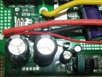
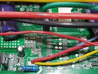
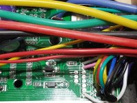
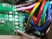
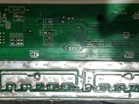
i am wondering what the green and brown wires that are soldered to the blue phase wire are used for?
i am wondering what the a3 litht blue wire is. i think it brakes but maybe a security wheel lock.
i am wondering if this can regen and how.
i am wondering if i could wire up any display. maybe one of the wires soldered to the phase wire is a rpm meter and the other a cruise wire?
i link to this controllers wirring diagram would be nice.


blue phase wire(green)?

blue phase wire(brown)?

xs(white) and 6/12(white) learn


a3(light blue) either wheel lock or regen or cruise?


sd(greenred) and 4.6v(red) and ground are throttle

k1(pink) and ground are low speed wires

k2(gray) and ground are high speed wires

sh(purple) and bat positive high break

sl(bluewhite) and ground brake low

dc(yellowgreen) and ground reverse
 

Attachments

  • 20240307_130909.jpg
    20240307_130909.jpg
    3.6 MB · Views: 9
  • 20240307_130951.jpg
    20240307_130951.jpg
    2.5 MB · Views: 11
  • 20240307_131007.jpg
    20240307_131007.jpg
    2.4 MB · Views: 10
  • 20240307_131033.jpg
    20240307_131033.jpg
    2.9 MB · Views: 9
  • 20240307_131045.jpg
    20240307_131045.jpg
    2.8 MB · Views: 8
  • 20240307_131100.jpg
    20240307_131100.jpg
    2.7 MB · Views: 11
  • 20240307_131121.jpg
    20240307_131121.jpg
    1.4 MB · Views: 9
  • 20240307_131125.jpg
    20240307_131125.jpg
    1.2 MB · Views: 10
  • 20240307_131158.jpg
    20240307_131158.jpg
    1.2 MB · Views: 10
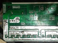
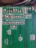
and if it does regen how would i set the charge voltage? i see a line of pins with voltage labels. thinking i would need to solder the corresponding pins to volts.
 
Unless it has software to program it, you can't set anything (including regen charge voltage). Most of the controllers with jumpers don't have any non-factory setup software (most don't even have displays with settings the user can change, or assist levels, etc...because if they did they wouldn't need the jumpers and hardware costs money).

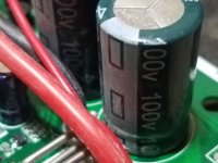
Those jumpers are for the controller base-voltage, which usually affects the regen voltage in those controllers that do regen and are designed for doing that, but how they affect it you would have to experimentally determine.

The controller base voltage determines the expected full-charge HVC and empty LVC voltages of the pack type labelled on the jumper (i.e. 48v = 52-54v HVC / 40-42v LVC, and determines the point at which the controller stops operating the motor (for accelleration or braking). You'd have to experimentally determine what this specific controller uses for LVC and HVC for any particular jumper, as even if it's the same "brand" as a documented one somewhere, unless it is identical hardware and firmware versions it may be different internal settings...and the factory "programming" may, even then, override anything.


i am wondering what the green and brown wires that are soldered to the blue phase wire are used for?

If they're actually electrically connected to a phase wire, they are probably for a "scooter/motorcycle" speedometer that uses battery-voltage-level phase inputs from a hubmotor to calculate speed (these speedos must be programmed by the end-user with the right number of poles, wheel size, etc, for that to be useful--there's a thread about an APT version of one of these around here somewhere).

Don't connect them to anything unless you are *sure* that thing can take a minimum of full battery voltage (there can be peaks of much higher voltage during regen braking, too)


i am wondering what the a3 litht blue wire is. i think it brakes but maybe a security wheel lock.
What specifically makes you think either of those? (just curious)

Unfortunately without a diagram there's no way for us to know for sure which wire is which on any random controller.

If you poke around, there are a number of threads (usually with "controller" in the title, sometimes also "wiring" or "wires") where people either were figuring out the wiring for a controller, or testing / reviewing it, or modding it, where some of the various pads on them may have been noted down for what their functions and markings were. No guarantee that any particular marking is the same on any two controllers (even from the same brand, or seller, etc--see the Greentime thread for some examples if hte pics are still there for them all), and almost certainly wire color isn't relevant, with the possible exception of black for ground and red for positive..but even there, red can be 5v *or* battery voltage, and connecting the one to the other usually makes for a very dead controller. :(

Even hall/phase wires may not be "standard"--I have one that's all green wires on all phase and all hall wires! (and it's only sensorless--it does not even try to use hall signals, at all, under any conditions, even though it has the wires).

One problem is that many of the "F1, 2, 3" or "A1, 2, 3", or "X1, 2, 3" type pins could have different functions depending on the firmware in the controller, and the only way to find out most of them is to try them out and see. Most of the input functions are activated by grounding the pin...but if it's an output grounding it could damage the MCU and kill the controller, so all experiments could leave you needing a new one. :/


i am wondering if this can regen and how.
Most non-programmable controllers that can do regen just have on/off regen at some preset amount, tied to the ebrake line. Some controllers have a high brake (12v or higher to engage, meant to connect to your brake light on scooter/MC) and a low brake (ground to engage), and most do the same thing no matter which one you use. A few only regen if one of them is used, and the other just turns off the motor. (which does what you'd have to experiment with, if you can experimentally determine which wire is which, or if it even has a brake wire).


i am wondering if i could wire up any display.
If it doesn't have a display connector specifically, then it isn't going to work with a typical display.

If you have some other kind of display in mind, you'll have to link us to a webpage with the info on it, or post all the info you have about it if you already have one you're thinking of.

i link to this controllers wirring diagram would be nice.
Without even knowing what brand/model controller it is, that's unlikely to be possible.

If you link to the place you bought it from, it might have info we can use to help you find more info.

If you post a pic of the labelling on the controller casing, that might also lead to more info.

The more you tell us about it the more info we have to help you with. ;) No guarantees that more info will help, but the chances improve.


xs(white) and 6/12(white) learn
6/12 is just 60 or 120 degree hall spacing. Most likely you ground this wire for 60 degree halls, and leaving it unconnected gives you 120 (the most common).

XS...there's different uses for that abbreviation on different controllers; I don't know which one yours is.


a3(light blue) either wheel lock or regen or cruise?
...there's different uses for that abbreviation on different controllers; I don't know which one yours is.


sd(greenred) and 4.6v(red) and ground are throttle
Probably.

k1(pink) and ground are low speed wires

k2(gray) and ground are high speed wires
Could be--different controllers use different pins for the 3-speed switch.


sh(purple) and bat positive high break

sl(bluewhite) and ground brake low

dc(yellowgreen) and ground reverse
Don't know; you'd have to test them...as noted, different controllers use various possible markings or pins....
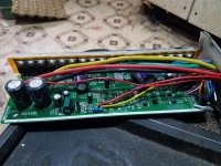
 
Unless it has software to program it, you can't set anything (including regen charge voltage). Most of the controllers with jumpers don't have any non-factory setup software (most don't even have displays with settings the user can change, or assist levels, etc...because if they did they wouldn't need the jumpers and hardware costs money).

Those jumpers are for the controller base-voltage, which usually affects the regen voltage in those controllers that do regen and are designed for doing that, but how they affect it you would have to experimentally determine.

The controller base voltage determines the expected full-charge HVC and empty LVC voltages of the pack type labelled on the jumper (i.e. 48v = 52-54v HVC / 40-42v LVC, and determines the point at which the controller stops operating the motor (for accelleration or braking). You'd have to experimentally determine what this specific controller uses for LVC and HVC for any particular jumper, as even if it's the same "brand" as a documented one somewhere, unless it is identical hardware and firmware versions it may be different internal settings...and the factory "programming" may, even then, override anything.


If they're actually electrically connected to a phase wire, they are probably for a "scooter/motorcycle" speedometer that uses battery-voltage-level phase inputs from a hubmotor to calculate speed (these speedos must be programmed by the end-user with the right number of poles, wheel size, etc, for that to be useful--there's a thread about an APT version of one of these around here somewhere).

Don't connect them to anything unless you are *sure* that thing can take a minimum of full battery voltage (there can be peaks of much higher voltage during regen braking, too)


What specifically makes you think either of those? (just curious)

Unfortunately without a diagram there's no way for us to know for sure which wire is which on any random controller.

If you poke around, there are a number of threads (usually with "controller" in the title, sometimes also "wiring" or "wires") where people either were figuring out the wiring for a controller, or testing / reviewing it, or modding it, where some of the various pads on them may have been noted down for what their functions and markings were. No guarantee that any particular marking is the same on any two controllers (even from the same brand, or seller, etc--see the Greentime thread for some examples if hte pics are still there for them all), and almost certainly wire color isn't relevant, with the possible exception of black for ground and red for positive..but even there, red can be 5v *or* battery voltage, and connecting the one to the other usually makes for a very dead controller. :(

Even hall/phase wires may not be "standard"--I have one that's all green wires on all phase and all hall wires! (and it's only sensorless--it does not even try to use hall signals, at all, under any conditions, even though it has the wires).

One problem is that many of the "F1, 2, 3" or "A1, 2, 3", or "X1, 2, 3" type pins could have different functions depending on the firmware in the controller, and the only way to find out most of them is to try them out and see. Most of the input functions are activated by grounding the pin...but if it's an output grounding it could damage the MCU and kill the controller, so all experiments could leave you needing a new one. :/


Most non-programmable controllers that can do regen just have on/off regen at some preset amount, tied to the ebrake line. Some controllers have a high brake (12v or higher to engage, meant to connect to your brake light on scooter/MC) and a low brake (ground to engage), and most do the same thing no matter which one you use. A few only regen if one of them is used, and the other just turns off the motor. (which does what you'd have to experiment with, if you can experimentally determine which wire is which, or if it even has a brake wire).


If it doesn't have a display connector specifically, then it isn't going to work with a typical display.

If you have some other kind of display in mind, you'll have to link us to a webpage with the info on it, or post all the info you have about it if you already have one you're thinking of.


Without even knowing what brand/model controller it is, that's unlikely to be possible.

If you link to the place you bought it from, it might have info we can use to help you find more info.

If you post a pic of the labelling on the controller casing, that might also lead to more info.

The more you tell us about it the more info we have to help you with. ;) No guarantees that more info will help, but the chances improve.


6/12 is just 60 or 120 degree hall spacing. Most likely you ground this wire for 60 degree halls, and leaving it unconnected gives you 120 (the most common).

XS...there's different uses for that abbreviation on different controllers; I don't know which one yours is.


...there's different uses for that abbreviation on different controllers; I don't know which one yours is.


Probably.


Could be--different controllers use different pins for the 3-speed switch.


Don't know; you'd have to test them...as noted, different controllers use various possible markings or pins....
xs(white) and 6/12(white) definitively is learn.
likewise the following are definitive.
sd(greenred) and 4.6v(red) and ground are throttle

k1(pink) and ground are low speed wires

k2(gray) and ground are high speed wires

sh(purple) and bat positive high break

sl(bluewhite) and ground brake low

dc(yellowgreen) and ground reverse

i figured that all out with poking and testing. all wires were cut when i got it and bought it used from ebay.

As for the a3(light blue) either wheel lock or regen or cruise. i figure cuz it brakes the wheel. it stops it when connected to ground but i aint used it when ridding. probably electric brake but i want to know exactly what this does before using it. i like knowing as much about stuff before i use it.
 
It*is* nice to know as much as possible about something so if it does something you don't want you can correct it more easily. :)

Under what specific conditions does A3 brake the wheel? Knowing the specific test(s) done and the specific result(s) of each may help determine what is actually happening.


For instance: That all-green-wire controller I've got doesn't actually have any ebraking, even connecting the pads together that on a visually-identical controller board do cause the ebrake input to brake the wheel or at least stop powering the motor. But, if I connect one of those letter-number pads to ground thru the brake lever (don't recall which one, but it's in the thread for it around here somewhere), then this enables the wheel-lock function, that will brake the wheel.

It's not designed for this purpose, and very rapidly heats the motor, phase wires, and controller, and it uses power rather than regenerating it, but it did give me some emergency braking if I needed it.

I don't use the controller anymore (it's a backup in case my usual ones fail; right now that's the Phaserunner v1 and v6, one on each rear wheel of the SB Cruiser trike) partly because of the sensorless-only operation, partly because of lack of "normal" features like ebraking, and partly because of the noises the controller makes constantly (a bit like an FOC controller can in sensorless mode, sort of a hissing, but it's not an FOC so it shouldn't do this), partly because of the complete lack of any documentation on it and lack of results during experimentation--it's a VERY basic controller...but it does work, mostly. (had to replace the capacitors early on, though).
 
i got it on an old bike upside down. i give it throttle and let the wheel spin for a second then touch a3 to ground. wheel stops. pretty fast but i figure it would stop slower if riding it but not sure. it may be trying to lock the wheel. i could turn it by hand but didnt turn it fast. im new to electric controllers but know electric can feed back and i dont want to burn anything. need a way to be sure before i move on. bike looks to scarry to try anyway so i aint in any hurry. im thinking this is to much for this bike frame. looks sketchy.

also why i want eletric brakes. no disk breaks.
 
you'll still need mechanical brakes--regen won't do the same job. you have no control over it it's just one braking force, not variable, and will have some limit of speed above which it does nothing and another below which it does nothing

what happens if you engage a3 without throttle? what does the wheel do, and what can you manually do with the wheel?

if it fights your hand rotation, it's not ebrake, it's antitheft/wheellock, and using it as regen may work or may blow up the controller or overheat motor/wires/controller.

if when you use it on the road it takes battery current to make it work instead of sending curent back to battery, as measured with a bidirectional wattmeter, it's not regen and is probably at/wl, with the same results as above.
 
a3 to ground does nothing when controller power wire is not connected. wouldnt be useful as anti theft if you had to leave the key on so i do not think it is wheel lock. when i engage a3 to ground with controller on and FORCE wheel to turn a little by hand it draws power. this indicates ebrake, right? but man that wheel is really hard to turn, i would be scared to engage that when moving.
 
x pin to ground seems to be regen. i get a momentarily volt increase when grounding it with wheel spinning. wheel stops fast but has no effect other than no throttle when grounded with stopped wheel. it is also easy to spin when grounded with wheel already stopped.
 
a3 to ground does nothing when controller power wire is not connected. wouldnt be useful as anti theft if you had to leave the key on so i do not think it is wheel lock. when i engage a3 to ground with controller on and FORCE wheel to turn a little by hand it draws power. this indicates ebrake, right? but man that wheel is really hard to turn, i would be scared to engage that when moving.

If the controller doesn't have power, it can't do anything, so you have to have both main battery power *and* the keyswitch/ignition battery-voltage wire connected, for anything at all to happen, with any function.

The KS/I wire provides battery power to the brains of the controller (so without this, the controller is "off", and can't control anything), while the main battery wires provide power to the powerstage (FETs / phases).


If those are both supplied, and A3 is engaged, but nothing else is, and you have to force the wheel to turn, and it's using up power to do it, it's wheel lock. That's what it is intended to do--make it hard for someone to ride off with your bike.

As I noted on my all-green-wires controller on the SB Cruiser trike, I did use this as an emergency ebrake, as there is no other ebrake function on it, but I would not recommend it at all--it's not designed to do this, and it could blow up the controller, melt the wiring and/or damage the motor itself (and if the motor isn't mounted properly, it could actually rip the motor out of it's mounts and damage them too).


If it were ebrake, it would have a little resistance, but not much, until the wheel is spinning fast enough to create electrical drag inside from current flow, and this would send power back to the battery. (for regen).


(There are other variations of ebrakes that do create force by using power, like the wheel lock, but not on basic controllers like this one; you'd need FOC controllers for that, and those would require programming cables and software to set them up with your motor, battery, and other system parameters. See VESC, Phaserunner, etc for common examples.).
 
x pin to ground seems to be regen. i get a momentarily volt increase when grounding it with wheel spinning. wheel stops fast but has no effect other than no throttle when grounded with stopped wheel. it is also easy to spin when grounded with wheel already stopped.
That sounds more normal for ebrake/regen behavior.
 
Since you probably haven't looked up the threads I mentioned before, I dug up the thread on that controller with all green wires:
and it looks like A3 on that one is the wheel lock.

Here's the stuff I determined mostly experimentally from one of the posts in that thread (there could be other info there more useful to you than these):

Mine (C-SMD1.2):
(where known I have used ** for your pad functions vs mine)

A3 4,83v ?active wheel lock? active low
A4 0v ?active wheel lock? active high
E4 reverse (anode diode yellow) active low
**E4 (reverse)
K3 5v ?no effect?
K0 5v grounding pulsed toggles between speed modes, regardless of 3speed switch setting.
K1 3speed switch (green)
**K1 (3speed switch)
ZF ?output? is 5V when speed mode is low or med, is 3v when high
K2 3speed switch (blue )
**K2 (3speed switch)
Q ?output? is 3V when speed mode is low, is 5v when med or high
**Q (cruise)
X 5v ?active wheel lock? active low When tied to DS, causes regen/wheel lock during braking
E1 self learn (gray)
**E1 regen (active low)
ZL 5v ?no effect?

DS 5v ?brake cutoff? (not regen) goes to 0.54v when sl=gnd When tied to X, causes regen/wheel lock during braking

SL Ebrake cutoff (White) (active low)
SH ?no effect? (white)

?speed mode indicator outputs? when 050 is med or high, when 550 is low
E5 0v
E2 5 v
E3 0v

YBS ?output? matches V hall signal?
H+ Hall power (no wire)
U U hall input (green)
V V hall input (green)
W W hall input (green)
GND (x5) Main signal grounds (gray from autolearn) (black from ebrake) (black from Hall ) (black from 3speed switch) (black from reverse)

+4.3V Throttle power (red)
SD Throttle input (green)
GND Throttle Ground (black)

XS ??matches throttle input signal?

+5v (x4) Hall Power (red)

A2 ?output? 0v normally goes to 5v when ebrake engaged
S- ?inverted S+?
S+ Analog output of one phase signal. (brown)

C1 Output Speed setting indicator Low
C2 Output Speed setting indicator Med
C3 Output Speed setting indicator High
(can put LEDs anode to Cx and cathode to ground, used 33k resistor during test as was handy, may not need one)

Are also some pads for B+ and B- on an unused relay outline; suspect they are for turning a brake light on and off, since the A pad above them goes to 5V when brake is engaged, but all the drive circuitry is not present for the relay either.


LED on PCB (and LED pad) Blink codes:
hearbeat 1hz = normal
2blink 1hz = ebrake on, same for wheel lock
no blink = motor running
(external LED can be added via LED pad)
 
Since you probably haven't looked up the threads I mentioned before, I dug up the thread on that controller with all green wires:
and it looks like A3 on that one is the wheel lock.

Here's the stuff I determined mostly experimentally from one of the posts in that thread (there could be other info there more useful to you than these):
thank you, man. i did look at your trike thread. i just got side tracked on a 48v controller after i figured out the regen on this one.

i also stumbled on a thread that mentioned that a phase wire is used in the security 3 wire plugs on controllers. aint locked into it yet but any info helps as i am figuring it all out fresh.

i will read through your green wire thread as i just got done probing the 48v one and can go no further on it until i garner more info on it.

really do appreciate you time.
 
got a amp meter and found that controller only draws 31 amp / 1500w at full throttle on 48v 30 amp hour battery. slow speed draws 20 and medium draws 25. is it normal for a controller to draw less than ratted amperage?

still looking for any more info on this controller to find more features.
 
Depends. How did you test it? Still upside-down with the wheel spinning in air?
 
Depends. How did you test it? Still upside-down with the wheel spinning in air?

no.it is still on rusted bike but i was ridding it when measured. also i put a different controller on it and that one was pushing 36amp and 1800watts. it is also rated at 40amp 1500watts so clearly these controller ratings are not exact.
 
Not knowing your amp measuring method, I am just guessing here. To force max amps output you may have to present more of a maximal load, like starting from 0 at the base of a steep hill, fully loaded, WOT. And if your battery is not up to it, the controller may never achieve max rated output.

Clamp amp measurement? (For DC amps that would be a more expensive meter.)
 
Back
Top