72v LiPo Pack 0-volts

juman

1 mW
Joined
Sep 25, 2021
Messages
18
Been playing with this project for far too long and my own negligence most likely caused this and at this point it's just learning. So building an ebike, have a 72v LiPo battery with BMS, battery was reading ~72v (maybe like 71v) last time I checked it but ya know life gets in the way so I didn't have it plugged into anything for 8-10 months then starting playing again.

At that time I did plug-in the charger to confirm it charged (saw voltage rise, charger went red LED) but since I wasn't ready to 'use' the battery with the motor yet I didn't leave it on charger so this battery was sat aside.

Now when I go test the battery with multimeter it reads 0v, nothing at all. If I plug-in charger, I see 83.9v on the output wires but the charger never goes into 'charging mode' and few seconds after unplugging charger the voltage goes back to 0. From what I gather I may have 'killed' my BMS which could mean cells are damaged so am trying to be careful but more just trying to understand all of what's going on here. Absolutely nothing on the battery has gotten hot/warm/etc when connected to the charger, it's like nothing at all is happening.

Is this normal behavior for a BMS that has died? It's almost like the charger voltage/power is just passing through the BMS but nothing is stored/charging in the batteries? I've also thought of maybe getting a different charger to see if that would be better but could also be a waste of money since this feels like a BMS/battery issue.

I do know that the true test here may be just opening up the battery pack and testing each cell, I just haven't moved to that step yet. More just trying to understand a bit before I move too fast/take things apart and I'm not opening a 72v battery pack lightly but either way here I want to learn from my mistakes.
 
The BMS should shut off (disconnect) the input and output if any limit is exceeded for any reason.

To find out what hte actual problem is, if it's not a bluetooth BMS witha phone app you can check it out on, you'll have ot open the pack and measure each cell group at the BMS balance connector pins. Preferably right at the BMS board itself, if that's easily accessible, otherwise at the back of the pins in the balance plug where the wires come out. If you can't get your probes in there you can use a pair of sewing needles with most of their length covered in insulation to prevetn shorts, just leaving the two ends enough clear to use them. (heatshrink, insluation stripped off of wire about the same size as the needle, tape, etc).

Start measuring from the main big batttery negative wrie to the first balance wire; iff they're designed right they should be the same point and measure 0V. Sometimes they use the main negtative as the ground instead, which sometimes causes issues reading the first cell by the BMS and balance issues can happen. But anyway, measure each pair of wires, from the first pair, then the more positive wire of the first pair and hte next wire up, and so on, until you measure between every set of two wires, for a total number of measurements equal o the number of cells in series. That should be 20 sets of numbers for a typical 72v pack.
Big thanks, read this last night and wanted to re-read today. More a learning experience here than anything, sounds like this weekend setup a work-space outside and remove the wrapping on it to see what's going on.
 
Take off any electrical conducting jewelry. A short going through a ring or other piece can do extensive damage in a fraction of a second.
 
Take off any electrical conducting jewelry. A short going through a ring or other piece can do extensive damage in a fraction of a second.
Yea being very careful with disassembly but think I'm basically done though because what I see means bad cells and this pack was so cheap it's not worth keeping around.

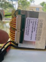
So I opened the battery covering, at first glance nothing abnormal but as I was looking it over, it almost looked like the BMS connector for the second 10 pins wasn't fully seated, it was worse before I took this pic:
20230818-Ebike_battery-01.jpg

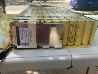
So think the BMS kinda just 'did it's job here' but the not fully seated connector may have caused slight power loss over time as well. This pic has better idea of that connector before I pushed it in.
20230818-Ebike_battery-02.jpg

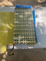
But the more concerning part to me is measuring the main leads directly from the battery yields 45v. While I haven't checked every group, an overall of 45v means averaging 2.25v per battery which to me is 'dangerous territory' with LiPo. I did go through a few of the BMS wires and it surely looked like each group was below 2.5v.
20230818-Ebike_battery-03.jpg


Basically this thing will now sit in my yard until I can get rid of it where some thief will think he's got something valuable only to realize he stole a....slight fire hazard :).

*runs off to buy lotto ticket since I never blew myself up*
 
2.0V isn’t danger territory. This pack still has a good chance of being revived with minor degradation. So long as no group sat below 1.5V for a long time they will usually come back to life you just must charge slowly with a variable power supply. For each cell in parallel I recommend charging with less than 100mA current. I do 50mA. So 8 in parallel would be 0.4A and set it so the voltage is 20S*3.00V per cell or 60V if I’m reading your BMS correctly. It should charge quite fast to 2.50 and then from that point going up to 3.00 will take a little time at 0.4A. Perhaps an hour or two, longer if they are high capacity cells.

Once you reach 3.00 in each group (individually charge each group if there is an imbalance greater than 0.05V per cell) you can double or triple the current and charge go to nominal, typically 3.65V for these cells. Might take the better part of a day to do this but it’s something you need to partially babysit outside. Use a laser thermometer to check temps. Better yet if you have a FLIR camera that makes it easier. Any cell 5 Celsius warmer than another, or a cell that goes over 40 Celsius at this low charge rate is a problem and your pack saving becomes much more difficult.

If all goes well and you stay balanced up to 3.65V let it sit for a week. If none of them lose more than 10 or 20 millivolts you are golden. You can do the final charge up to 4.10 or 4.15 with a similar low current and continue monitoring outside for any cells behaving unlike the others. Don’t go up to 4.20V yet, it’s just not worth the risk. Let them sit for a week again and check to see if they lose voltage. Losing 10 or 20 millivolts is ok, losing 40 or 50 is not a good sign. If it all goes well and you want to top it off to 4.20V then do that as well. Follow that up with a capacity test (Atorch DL24 is $25 on Aliexpress make sure you use the 4 wire connection for accurate voltage sensing). As long as you get 80% of its rated capacity between 4.20v and 2.50v then it’s likely still a good pack. If you don’t want to go down that low then go down to 3.00v and assume that’s about 20% that you’re missing out on roughly. So look for at least 80% of 80% of the stated capacity (64% I think).

*the cheapo DL24 is 150W max. Use an extra fan and some small feet underneath it to increase airflow over the mosfet since a 2A discharge would be 170W so you’d have to do 1.75A. Running it over 100W absolutely requires the additional fan. Even a PC fan will work so long as you raise the device up 6 inches to allow the PC fan to run cool air under it. They make other modules including a modular unit that starts at 150W/25A max. Every module you add increases the max load by 150W and 5A. I have the 600W/40A module. It’s not the greatest design but for $65 it was a deal. The stock heatsink in these new modules are garbage and the fan only runs once you hit a user programmed temp. This DL24MP model DEFINITELY requires additional cooling. I use a 12” desk fan and blast it on the highest setting with the device elevated 6 inches off the table top. The fan cools the mosfets underneath and the resistors on the board while the built in fans are set to turn on at 40 Celsius to just cool down the heat sinks. This model would allow you to run a 7A discharge but honestly the $25 model is good enough for you it will just take quite a while. At $25 it’s a very useful tool, you can even discharge powerbanks to make sure you’re getting what you paid for.
 
I see it’s a 50Ah battery…so a 1.75A discharge would take over a day….but with 200 cells I think it’s worth buying the $25 load tester and if you don’t own a variable power supply I can point you to some cheap low amperage options. You could even cheap out and get a simple buck converter and charge each of the 20 groups. There are some that have great displays and are easy to use for less than $20 and can be powered by just about anything but an old laptop power supply or just a basic 12V 3A power adapter would do. You could go even more basic and get little modules with no display for $5 each and buy a few of them to speed things up.
 
Use tape around the finger bling if the bling is not easy to take off.
 
But the more concerning part to me is measuring the main leads directly from the battery yields 45v. While I haven't checked every group, an overall of 45v means averaging 2.25v per battery which to me is 'dangerous territory' with LiPo.
Those aren’t LiPo cells. They are lithium ion/li-ion.
 
Back
Top