A2B battery help needed

I need to keep in mind that I really just want to get this bike going and enjoy. Even though I want to use both batteries, I don’t want to invest in tools I really won’t use again.

Just need to repair, rebuild or refurbish these batteries in the most cost efficient and reliable way.

A low current capable charger seems to easily go for $100 or more around my area and that’s with no guaranty that I can save these 8 year old cells. And even if I do revive them...will they last for many more years. Also, is there a chance they can swell up in the bike frame getting stuck forever.

It may be more value added to cannibalize a $5 microwave on Craigslist, build a battery tab spot welder and put the $100 towards new cells and rebuild the pack using the original case and BMS.....

Still new at this so I will keep on searching for options. Any and all advise is still welcome please.
 
Nice job on the battery rebuild! I have a pile of cells and the welder, just not the time yet. Glad you posted a picture of it, gives me a good idea what's ahead.

alfgar, I know your situation. My budget for bike stuff is real limited too but I have lots of equipment.

It would be possible to just use your existing charger and a resistor in series with the pack to jump start it. The resistor could be an incandescent light bulb, regular 120v type, maybe 60w or less. This should drop the current enough to be safe. You still have to pull the pack apart to get access to the terminals on the BMS board. You don't have much to lose by trying this.
Keep an eye on the pack voltage while charging and don't leave it unattended until you're sure nothing is getting warm.
 
Fechter:

I already opened up the pack so it shouldn’t be much of an effort to try your recommendation.

Just to be sure I got this correctly:

I use the bikes charger and connect one of its leads (let’s say the negative lead) to one of two light socket wires . I take the other light socket wire and connect to the negative lead of the battery. This is the negative lead that comes from the battery to the BMS, basically bypassing the BMS.

I then take the positive lead of the charger and connect it to the positive lead (white wire in my case) that comes from the battery to the BMS, again bypassing the BMS.


BUT do I disconnect the battery leads from the BMS. If I don’t, I will also be feeding 36V to the BMS....which is what the battery does anyways when fully changed.....I assume. :?

** Can I put my meter on this setup to measure the amperage so I know for sure what amps I am pushing?

And can I use my lower amperage lawn mower charger instead of the 4 amp bike charger that I have.

999zip999

I live in a suburb not far from Montreal

Not sure if I can ask this here, but where could I buy these new monster cells, and at what cost?
 

Attachments

  • 20170326_172353small.jpg
    20170326_172353small.jpg
    99.8 KB · Views: 2,187
Yes, sounds like you have the right idea. The BMS can stay connected. One side of the existing charger connection should already be a direct connection to the battery (usually the positive side) so the bulb could just bridge the other side. Let me check the extracted BMS unit I have here and see if this is true. Otherwise your plan of using wires to bypass is OK.
 
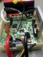
the left big white wire in the top of the picture is the positieve to the Batterie and the right on top is the negative to the batterie.
check the voltage on these wires....i think if there is 21volt you can charge the pack easy with a 1A 29.4v 7s lithium charger.
 
alfgar said:
At each cell pack that I measured I got .14V / .15 volts

At most all individual cells, I measured .14 V / .15 V although there was one at .19V and another at .12V

At the “big” black and white wires from the battery pack to the BMS board, I got 1.45 volts.

At the red and black terminal that go from the BMS to the bike connector, I measured 1.15v. Interestingly enough, the longer I left my voltmeter there, the more the voltage counted down incrementally: 1.15V then 1.10V……. .80V, .79V and so on for as long as I had the meter on it. ?????

.
I had noted the voltages on and earlier post.... no where near the double digits on those two terminals.... 1.45 V

Please keep in mind that for now all I have is the bike charger and a 36v charger for my electric lawn mower.
 
The BMS in your picture looks quite different from the one I have, so hard for me to tell if there's an easy way to just hook the light bulb up to a pair of terminals. I guess going from the charger, though the bulb and straight to the cells with wires would be your option.

The light bulb will act as a current limiter. You can estimate the current by how bright it gets. You just want to get some charge into the cells at a low rate to try and revive them. If everything is working properly, it will take quite a long time, like several hours or more.
 
Not too concerned about how to connect.... Was going to unscrew the black and white connectors from the BMS and connect the charger to those battery wires with the light bulb in series.

It is the unfamiliarity that bugs me a little I guess. Once I do all this and turn on the charger I will definitely be monitoring very closely. May even switch off the power every 5-10 mins at the beginning to take cell voltage and checking for warm cells. If this goes well the first few 5 minute intervals of charging, I may let it go for 30 mins at a time.

Either way, this will need to wait a while as I’m in the middle of a kitchen remodel the next few weeks.
 
If you are serious about reviving this pack, i think you are going to need more than just a bulk charger.
At some stage you are likely going to want to charge single cell groups (4.2 v) so i suggest you invest $25 in a cheap RC charger , or hunt down a cheap single cell (phone ?) type wall charger.
 
Again, this is all new for me so just need to be sure:

You're suggesting I get a 4.2v charger and individually charger each cell...one by one?

Do I just connect the charger leads to each side of the cell and let the charger do its thing, Obviously I will monitor (heat, cell voltage, etc) and stop anywhere above 4 V.

*** I am assuming I do not need to disconnect the cells from the pack (removing the tab welds) while charging.

Now’s here’s the fun part, I do this for all 60 or so cells... one by one? This will obviously take some time, but usually the best and safest ways do take the longest.

I have all kinds of adapters (1.5v, 3v, switch adjustable 1.5 to 9v, etc) that I have accumulated throughout the years for various electronic equipment....can I use one of those? Or is a charger not the same thing as a power adapter. Don’t mind spending the $25 if it’s necessary considering the cost of the alternatives.

Can’t tell you all how much I’m learning here, really appreciate it....may have just found a new hobby. :D
 
The pack is made of 10 groups of cells connected in series. To do the single cell charge, you would connect the charger to one group and let it go, then repeat on the other groups. Each group contains (6?) cells connected in parallel. This get treated as one big cell. Yes, this can be done without disconnecting any of the cells.

Doing individual cell charging is the best way to balance a severely out of balance pack. You still don't want to charge a cell group with normal current until the voltage has been brought up to at least 3v or so.

I would try the bulk charge with light bulb to see if you can get the cells to come up. If it comes alive again and the cells seem to be working, then the individual cell charging would be nice to get it all perfectly balanced. From the sound of it, the pack is perfectly balanced already. All the cells are completely discharged.
 
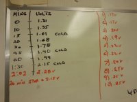
Spent some time on both battery packs today. Only had a 26V 1.5A charger available so went ahead and used it , with a 100W light bulb in parallel while bypassing the BMS.

Battery pack voltage did rise but it did so VERY slowly. The entire pack barely gained 1V over a two hr period....will likely try with a 60 watt bulb tomorrow. The pack was cold to the touch the entire time.

Each of the 10 cell pack voltages are indicated on the pic as well...on the right in red.

May be a stupid question: If I ever get the battery to 26V...do I need to find another charger? Or will the charger push the pack over the 30 Volt mark by leaving it connected even though it’s a 26V charger.


Will shortly post my findings as to the external B battery
 

Attachments

  • 20170416_214216.jpg
    20170416_214216.jpg
    66.9 KB · Views: 1,560
External B battery

Will not be easy to keep this one short but here it goes.

As stated on an earlier post. The B battery will charger to 41+ volts but will go to 0 volts as soon as I put a load on it such as my spare 36V motor. It will sputter on for a split second every 12 to 15 sec’s rather consistently until I remove the load. Then it’s back at 41 volts again.

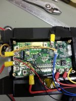
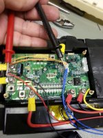
Pic B Battery BMS: Is the BMS

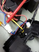
Pic B Battery BMS 4: The black probe is pointing at the battery on/off luminescent switch. It is luminescent when turned on and measuring 41 volts but goes off (0 volts) when I connect a load. The luminescent button sputters at the same time as the motor every dozen seconds or so.

The red probe is pointing at the connector I would like to hot wire (bypassing the switch) but have no clue how to.

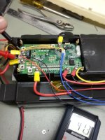
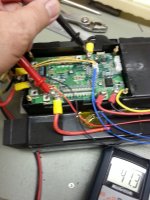
Pic B Battery BMS 3: Probes are showing where the on/off switch wires connect to the BMS.

Pic B Battery BMS 1: the red and black probes are pointed at the positive & negative that connects to the bike....to which the voltage goes to zero when the load is connected.

Pic B Battery BMS 2: The red and black probes are pointed at the positive & negative leads that come out of the pack and connect to the BMS, also measuring 41 volts. When I connect the motor to these two terminals....the motor works good and continuously.

So basically I know the cells are good and will power if I bypass the BMS entirely but what on the BMS is no good?

I would like to eliminate the on/off switch as the culprit? How do I bypass the on/off switch..which wires of the switch connectors do I connect together? Picture B Battery BMS 3 shows two blue wires, a black and a red on the BMS board.

Reminder: I have no training in electronics and am just going by my logic....eliminating one variable at a time.

Thanks in advance for any help.
 

Attachments

  • B Battery BMS.jpg
    B Battery BMS.jpg
    213 KB · Views: 1,563
  • B Battery BMS 4.jpg
    B Battery BMS 4.jpg
    148.8 KB · Views: 1,563
  • B Battery BMS 3.jpg
    B Battery BMS 3.jpg
    232.8 KB · Views: 1,563
  • B Battery BMS 1.jpg
    B Battery BMS 1.jpg
    202.7 KB · Views: 1,563
  • B Battery BMS 2.jpg
    B Battery BMS 2.jpg
    188.5 KB · Views: 1,563
hi alfgar
not sure if you have done this already but on your external B battery you need to take off the foam and plastic covers that hide the cells and check out the nickel strips.
it seems the designers thought that the cells don't need securing bc they are held in place by the nickel... so as a result they slide up and down in there holders until, who would have thought, the nickel breaks.
I assessed one recently for BMS issues ( it was a year old) and there were multiple nickel strip fractures. another A2B fail :pancake:
worth checking if you haven't already
 
Will take a look at the strips kdog but I would think that if this is the case for me, the motor would not work as well when bypassing the BMS as I did using the terminals on Pic B Battery BMS 2:

Regardless, will use your advise as a preventative measure and see what I can do to secure them.

Gut feeling is on the on/ off switch but I need to know how to bypass to be sure...something is telling me that I need to connect the two blue wires together but I won’t take that chance until I get a confirmation.

tks
 
On the internal pack, yes try a couple of bulbs in parallel or whatever to bring the current up a little. It should be slow, but not that slow. Around 100mA should be safe.


On the secondary pack, if the button makes the light go on/off, then the switch is good. The BMS is tripping for some reason. That is usually due to one cell going low voltage under load or if the current is too high (over 30A). If you put a weak load (maybe that 60W light bulb) on it, you could measure the individual cell voltages looking for a low one. Could just be a bad BMS too.
 
Main frame battery:
For the main frame battery, i switched to the bikes 36V charger and placed a few bulbs in series giving me around 110ma. Much faster rate of charge. About 1 volt for every 20-30 mins or so. Doesn’t seem to hold at the voltage that I stop at when I need to leave the house for a hour or so. May be that I need to get it to its full charge to hold better...we’ll see when I get there i guess. Not sure when I get to the higher voltages but for now the pack is nice and cool. At 28 volts as I’m typing this.

Secondary battery pack:
Didn’t get too far with the secondary pack as far as testing. But did get a chance to bypass the switch and as you predicted fechter, It wasn’t the switch. Didn’t put a bulb on it while measuring the cell voltage but opened it out and measure the cell packs through the many access port holes. Guess that’s what the holes are for. All cell packs measured at 4.1 V but I never measured the cells under the light bulb load. Although the battery was able to light up a 60 watt bulb.
 
It official, the main A battery is ALIVE. Not sure for how long but it definitely held its charge (41.5 volts) overnight and throughout the day today. I began charging through the BMS once it went over 30 volts and the smart charger took over until the light went green.

All cell packs are at 4.15 volts, , except for 1 at 4.19V.

Connected it to the bike and it works well. Only time will tell as to how long it will really hold a charge and what I can get out of it long term.

THANK YOU to everyone, no way I would have done this without the help. Seems straight forward enough now but would never have gotten it by myself.

Any “last” advise? Should I run the bike until it discharges fully and then recharge fully again...or top off the battery every night regardless of voltage level.

Thanks again :D .....now for battery “B”.
 
Run the battery through a few full discharge/charge cycles to be sure the BMS etc doesnt have any faults, and the pack is stable, staying cool, and safe.
Manually recheck each cell group to be sure they are staying balanced.
Never leave it fully charged (4.2v) , or fully discharged.
3.8ish v is a good storage level.
4.0-4.1v is ok for days, and you can still top it up quickly to 4.2 for max range, just before you ride.
 
I'd be curious to see what kind of capacity it has left. It might be pretty good depending on how many cycles the pack had.
 
fechter said:
I'd be curious to see what kind of capacity it has left. It might be pretty good depending on how many cycles the pack had.

If you tell me how to measure the capacity I can give it a try.

All I can say is that it seems to last rather long under no load.

In order to have access to the battery while it’s connect to the bike and draining, I have the bike upside down with the throttle locked to the ½ position and the wheel is just spinning. After an hour of this last night it barely lost 1 volt.
Not sure how else to fully drain and charge the battery & easily monitor temperature and cell voltages while doing it.... unless there is a house hold load you can suggest I connect while on my workbench. I assume it would be more than just a 100W light bulb :? ?
 
I'd charge it up and go for a long ride. A long ride that never gets you far from home so you can pedal in the event it reaches full discharge and cuts off. When the pack is new, it might get 20 miles without pedaling if you're lucky. At 20mph, that's about an hour.

The only way to really measure capacity is with an amp-hour meter.
 
Joachim said:
i already rebuild a A2B frame pack and the bms looks just like a simpel one...no reset option/button.
the pack original 10s 6p 11.25Ah .. after rebuild with 3500mah sanyo GA cells with succes i test the pack with a constant 6A discharge,result in 21.6Ah :mrgreen:
I think you can use a regular 10s li-ion bms for this bike,no extra wires to the controller just minus and positieve for charge and discharge.

to check the cell voltage you dont have to open the compleet pack,just open the side of the bms and pul out the sense wire conector:use a multimeter negative probe on the first black sense wire and you can check al 10 poles in the conector with the positieve lead from the multimeter.
I think a pack thats extreem low(2.3v are les) in voltage wil never give a good and save perfomance again :?:
jt1hly.jpg

rc7pjl.jpg

2hy9t7q.jpg

bjal1y.jpg


What was your cost to rebuild the pack? A shop can rebuild it, but I'd try to learn how myself if it will save money.
 
my frame battery gave up on me as well. Does anyone have a working frame battery from an A2B Metro battery?
Please let me know.
 
Back
Top