A2B Ultra Motor Identification

daveo12345

1 mW
Joined
Nov 27, 2019
Messages
16
Hello, first post. I recently bought a brand new a2b velociti. The bike seems to be similar to a2b Metro and a2b hybrid overseas.

The bike was missing the battery. I've made a very nice battery pack 36v using greenworks 40v batteries and diodes to protect each. However, I've a few questions.

1) The a2b velociti seems to be different in that it only has the rear 1 battery, no frame battery. Can anyone confirm for sure? The manual does not reference a frame battery

2) The battery plug pinouts are discussed for the metro in other threads. However, this is one with 6 not 5 pins. I'm guessing the small pin next to the plug "key" and the pin opposite are used in the bms and not necessary to get the bike going?

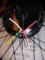
3) I found the "switch module" in the frame....which i am guessing is not quite a controller. The switch module inputs the brake cutoffs, throttle, and passes 7 wires to the wheel assembly via 1 big wire which really contains 2 thick (Red black directly from battery) and 5 small wires control (yellow / blue / white/ and two others) via another small plug connector. I am guessing the 5 wires are control wires from the switch module which looks like a controller is in fact just a switch module and the real controller is in the hub? If so, there is a youtube of a guys shorting the miniplug on a a2b hybrid, causeing the powered wheel to run at full throttle.

could i add a separate controller by using the second controller, passing motor output of the controller on the existing thick wires to the motor, shorting the proper pins on the OEM motor miniplug, and get away with not disassembling the hub? If the 5 (really 7 counting power) wires going to the motor on the oem are 1. voltage for power 2. ground 3. brake cutoff (compost meaning l/r) 4. throttle voltage and 5. unknown (TBD) I should be able to provide voltage on perhaps 1 and 4 and get full power from the red and black and if the external controller limits this, thus the external controller is in control and i did not have to disassemble the hub?
 
daveo12345 said:
I recently bought a brand new a2b velociti.

The bike was missing the battery.
Not that it matters, but it is very odd for a brand new bike to be missing a major component like it's battery, and the seller to be unwilling to help with that? Or perhaps was it something like a store demo bike (not really "new") that they just discounted so they could keep the battery?


1) The a2b velociti seems to be different in that it only has the rear 1 battery, no frame battery. Can anyone confirm for sure? The manual does not reference a frame battery
AFAIK there is only teh rear rack battery system on that bike.

could i add a separate controller by using the second controller, passing motor output of the controller on the existing thick wires to the motor, shorting the proper pins on the OEM motor miniplug, and get away with not disassembling the hub? If the 5 (really 7 counting power) wires going to the motor on the oem are 1. voltage for power 2. ground 3. brake cutoff (compost meaning l/r) 4. throttle voltage and 5. unknown (TBD) I should be able to provide voltage on perhaps 1 and 4 and get full power from the red and black and if the external controller limits this, thus the external controller is in control and i did not have to disassemble the hub?

AFAIK all the A2Bs except one use the internal controller in the Ultramotor hubmotors. This post also says that:
https://endless-sphere.com/forums/viewtopic.php?f=2&t=30050&p=1157892&hilit=velociti+hub%2A#p1157892
though you'd have to verify this yourself on the bike you have.

In that case, if you want to change the controller, you have to take the wheel apart on one side, so you can pull that half of the motor cover off, to take out the internal controller, and run phase and hall wires (unless you go sensorless) out from inside the motor to your new external controller. You can get good cable for doing this by the meter from http://ebikes.ca, with or without waterproof connectors already on it.


You can't use an external controller without doing this, becuase otherwise there is no way for it's power to get to the motor.

You can't modulate the battery power going to the internal controller to control it, either (which is what it sounds like you want to do); it needs a smooth continuous steady power source to operate correctly, and doing what you are talking about would prevent that.

If you want to try it anyway, you'd need a brushed motor controller capable of handling the current the system will require, and some hefty capacitors and inductors to help smooth it's output. This controller would go between the battery output and the motor's battery input. Then your throttle would have a limited ability to control the motor's battery input, between the built-in controller's LVC and HVC. Between those two points it would shutdown, and not operate at all.
 
I recently bought a new in box A2b Velocitui without battery and an Extra a2b Ultramotor wheel.

The velocity has a 24 wheel with an internal controller / 8 pin wiring harness and an external switch unit which seems to provde lights and take care of switches and connections.

I connected to a battery, where i had lights but no motor. Long story, I ripped out all of the wiring, everything.

So having an empty shell, I looked at the extra wheel. It was a 9 pin with 3 large pins and 6 small. I got to thinkin this must be an a2b which supports an external controller. I THOUGHT IT WAS A 3 PHASE MOTOR WITH 6 PINS, 3 HALL AND 3 OTHERS. Not finding a female connector, i DECIDED to cutoff the connector.

The color codes have me scared. The three big wires are red, black and white. The 6 smaller wires are red, orange, block, blue yellow.

Now because of the colors what i am thinking is that this is an internal controller motor, and that the three large wires are for the two batteries.

Can anyone with a metro verify? I really wish this was a 3 phase external controller unit and for somereason a2b uses non standard colors.

See picture. I guess to could be for two batteries :(
 

Attachments

  • bbb.jpg
    bbb.jpg
    56.9 KB · Views: 1,339
recently bought a new in box A2b Velocitui without battery and an Extra a2b Ultramotor wheel.

The velocity has a 24 wheel with an internal controller / 8 pin wiring harness and an external switch unit which seems to provde lights and take care of switches and connections.

I connected to a battery, where i had lights but no motor. Long story, I ripped out all of the wiring, everything.

So having an empty shell, I looked at the extra wheel. It was a 9 pin with 3 large pins and 6 small. I got to thinkin this must be an a2b which supports an external controller. I THOUGHT IT WAS A 3 PHASE MOTOR WITH 6 PINS, 3 HALL AND 3 OTHERS. Not finding a female connector, i DECIDED to cutoff the connector.

The color codes have me scared. The three big wires are red, black and white. The 6 smaller wires are red, orange, block, blue yellow.

Now because of the colors what i am thinking is that this is an internal controller motor, and that the three large wires are for the two batteries.

Can anyone with a metro verify? I really wish this was a 3 phase external controller unit and for somereason a2b uses non standard colors.

See picture. I guess to could be for two batteries
 
A2B uses non-standard wire colors. Between the internal controller and motor on my Metro, it uses black, red, and white for the 3 phases and corresponding halls. You can measure resistance between the heavy wires to make sure. If they are phase wires, you will see near zero resistance. If there is an internal controller, it will give you a time varying reading as the capacitors charge.

It will be a bit trickier to figure out the hall wiring as you don't want to apply power without knowing what they do. Having the matching controller would take out a lot of guesswork.
 
It's pretty normal to have 9 coming out of a regular brushless motor. 3 phases, 5 Halls (red and black, then three signal outputs,)
and the white speed sensor output. Internal controller often just had two power wires, as all the rest happens inside.
 
Thanks guys, so your best guess looking at this wiring is that it is indeed a 3 phase non internally controlled?

If so any idea on how to determine the other 6 wires

3 halls, 5v?, grnd and speed?w

Any recommendations on an external controller? Thinking dual mode controller and start off with sensorless?
 
Well, having owned a Metro, Velocity, and still posessing a external controller and hub for a Metro,... i can confirm that the hub does have a 9 pin connector for the external controller. 3 large and 6 small pins.
Unfortunately the external controller is “fully potted” so there is no easy way to tell what those smaller wires are doing other than the obvious hall sensors and A2b always used a thermal sensor ( big problem !)
Your velocity “controller hub can be run just by connecting 36v power direct to either the 2 big wires going to the hub, or to the +, -ve pins in the battery connector

The battery plug pinouts are discussed for the metro in other threads. However, this is one with 6 not 5 pins. I'm guessing the small pin next to the plug "key" and the pin opposite are used in the bms and not necessary to get the bike going?
Yes, you only need the +ve and -ve pins in the plug to run the bike hub, but other connections may be needed for lights, battery on/off , BMS control, etc etc depending on what you have in your pack.
Looking at the pins, with the locator key at the 12 o'clock position..
2 pins on the right at 2 o'clock and 4 o'clock are Negative polarity (both, connected in parallel !)k
2 pins on the right at 8 o'clock and 10 o'clock are Positive polarity. ( both connected in parallel )
PS i would not plan on finding a matching (battery side) female plug ( mine was magnetic retention ?) for your battery, i searched world wide for one with no luck !
I also bought my Velocity new but missing the battery (??) and even though i did obtain a Metro rear battery, the connectors were different, so i ended up making an adaptor coupling as a solution.
 
So I think I've confused the issue a little bit.

I do have a Velocitti, but in the midst of things, I messed something up and ripped out all of the wiing.

With all the wiring out, I am going to replace the rear wheel with the rear wheel of the Alva+ a2b which has a 9 pin connector, which I cut off and now have these 9 wires, 3 big and 6 small as depicted in the picture.

Sounds like everyone believes this is a 3 phase motor, so i plan to buy a controller, external and am looking for one with the learn function and also supports sensorless operation. Then i can fool around with it until i find something which works.
 
A very nice person gave me the wiring diagram for the Alva+ and please do compare to my photo of the cable i cut off of the rear wheel.

So Everything makes sense except, I have a white wire on the photo of the connector, and the wiring diagram shows a "green" which is missing.

Can i assume the person wiring up this thing ran out of green, or mistakenly grabbed a white wire?

Also the orange is NTC. what does that mean?
 

Attachments

  • bbb.jpg
    bbb.jpg
    56.9 KB · Views: 544
I wouldn't make that assumption. I would take the extra hour and open the side cover and trace the wire/s in question. It could save you the time it would take to replace a blown component like a hall sensor.

:D :bolt:
 
unfortunately the motor halves are internal to the spokes, so to separate its a completede spoking
 
NTC is probably the temperature sensor.

The white wire is probably a signal return wire from one of the motor Hall sensors.

Time for some diagnostics. But before you go there, are you wiring this motor to an existing cable? Or are you going to re-do the entire cable? The reason I ask, is if you are going to an existing cable it could make the testing much simpler.

What you are endeavoring do is to find out if the white wire is a return voltage wire from one of your Halls. What you need to do is send a very low current 5v (a depleted 9v battery will work. So will three AAA batteries in series) to the Halls by hooking up the small red wire with with a 5v+ voltage and use the black wire as the ground. Then while holding the axle in place, slowly turn the wheel backwards to see if the Halls latch on and off by connecting your meter to the black wire ground and then one at a time test the white yellow and blue wires. They should latch from 0v to about what ever your positive voltage is.

If you have red and black wires connected to the controller, and are getting a 5v reading then so much the better.

If you haven't tested hub motor Halls before, check this out.https://www.ebikes.ca/documents/HallSensorTestingFinal.pdf

Be sure to write down your results so you only have to test once.

:D :bolt:
 
If it helps, on the Ultramotor I have here, internally, red, black, and white are used for phases (thick wires) and all hall wires (thin wires, one color per phase / hall).

But it was an internal controller puck, so could be different from yours.

https://endless-sphere.com/forums/viewtopic.php?f=2&t=86600
 
amberwolf.

Since your bike shares the same phase wire coloring, do you recall the _dc5v and grnd wire coloring.

of course, if my halls correspond to red white and black, that leaves me with orange yellow and blue for possible5vdc and grnd.
 
daveo12345 said:
Since your bike shares the same phase wire coloring, do you recall the _dc5v and grnd wire coloring.
My bike does not; it is not referenced in the post above.

The Ultramotor I have does have the coloring I listed, which includes all of the hall wires as noted in the post.

Please see the linked thread for the pictures and information that show the wiring and colors I described if that doesn't make sense.
 
Hi

I am new to ebikes and attempting my first build as a hobby

I have a cheap controlller, 1000w from china/amazon

I am attempting to hookup to motor (3 wire), all sensors (5wire), throttle (3 wire) and power (2 wire).

Should this give me power?

With the power connected to the controller i am not getting +5v on the throttle wire.

Thinking bad controller?

Is there any on /off switch which needs to be connected/grounded to activate a controller? brakes do not have to be connected correct?

Here's a pic for reference . I should have to do anything else other than power to get the +5v for the throttle and if no power there it must be bad correct?
 

Attachments

  • new  controller.gif
    new controller.gif
    122.7 KB · Views: 237
I am new to ebikes. For my first build I'm close, but in configuring my controller I have a "learning mode" for a cheap chinese controller.

It worked, i connected learning wire, powered on, wheel spins forward. Oddly with throttle wheel reverses direction. in proper spinning direction i disconnect learning wire and then disconnect power.

Bike works, but runs a little rough especially at beginning <from stop>.

Question: How do i know the controller has adequately programmed (digested) the halls. Could it be operating in sensorless mode? How would i know?
 
trying to configure my first ebike.

when i use leanring mode, wheel spins forward. However, when i apply the throttle, the wheel reverses.

Everything i read says it should not do this, but rather increase and speed and not reverse unless i disconnect and reconnect the learning wire.

Anyone know if this is correct?

Thanks in advance.
 
daveo12345 said:
trying to configure my first ebike.

when i use leanring mode, wheel spins forward. However, when i apply the throttle, the wheel reverses.

Everything i read says it should not do this, but rather increase and speed and not reverse unless i disconnect and reconnect the learning wire.

Anyone know if this is correct?

Thanks in advance.

Can you clarify; are you using the throttle when the self learning wires are still connected??


Sent from my iPhone using Tapatalk
 
yes i am doing in this order

1. connect self leanring wires
2. connect power
3. wheel starts spinning in forward direction (without any throttle as soon as power is connected)
4. If i apply throttle, wheel reverses direction
5. apply some throttle again, wheel reverses back to proper direction
5. disconnect learning wires

bike does memorize the forward direciton. but my real question is are the halls memorzed or is it operating in a sensorless mode
 
daveo12345 said:
bike does memorize the forward direciton. but my real question is are the halls memorzed or is it operating in a sensorless mode

Sounds like sensored. Do the self learning again, but disconnect when the motor is running in reverse. Disconnect, and see if it remembered it. Then, unplug the halls, and see if it goes the right way.
 
Back
Top