dawrench said:I will check. Does the voltage rating of the switch matter?
It shouldn't matter much. It doesn't really take much current.
dawrench said:I will check. Does the voltage rating of the switch matter?
Did you see this one?:nicobie said:Sure wish I could buy one of these that would switch 100V. A kit would work for me if it came with a bare circuit board.
I'm sick and tired of having to fix my large DC contactor every time some idiot flips the main switch without using the pre-charge button.
??? that's the main reason to use them. as the topic says: active precharge. this circuit replaces the precharge resistor to avoid sparks. for more convenience an on/off switch was used.dawrench said:Can one of these be used to stop controller sparking as well ?
no worries. i never got a problem with charger sparking. i turn on the charger first and then connect it to the battery. i you do it the other way round there are sparks. but maybe my bms helps as well!?
 those fets are good for a LOT of amps!
Diamondback said:


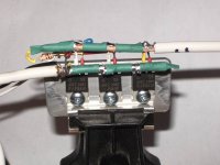
sacko said:Can anyone spot what I have done wrong?
When it was connected, everything was off; perfect. When I turned the switch on though, 2 fets blew.
All though the solder looks very close underneath, there wasnt any solder that had bridged.