Adaptto Mini-E/Max-E Owner's Thread

Adaptto going into limp mode.....

An update to my previous post.
I ran some hills yesterday making sure I kept motor temps down under 100 deg C the entire ride.

My Midi-e still quit on me twice going up a hill. Battery pack was at 60% showing 84v. Never happens on the flats no matter how hard I push it.
Hit the controller with a temp gun when I got home showing 41 deg C.

My conclusion is that there must be voltage spikes forcing the controller into limp mode when going up steep hills.

Solutions???
-Rebuild my battery pack from 22s to 20s...buy new BMS
-Unlock firmware and hopefully it won't happen.....at the risk of blowing the controller.
-just live with it.

Any insight from the experts is highly appreciated.
Thanks
 
Before using a cooling solution on my Mini-E's, they used to regularly go into limp mode, try the same hill/s and check the controller temp instead of the motor, hit either 50 or 52degC and it'll start limping. 40 degC seems quite high after a ride. I know I'm light, but running 30 Batt Amps at 85.8v nominal for 24 miles pretty much WOT 56kph AVG only just gets the controller to 47C and then it drops below 30C within 2 minutes.. Was the Temp gun at immediate hand?

Only suggest watching this as I run 26S LiFe when fully charged @ 3.65v = 94.9v HOC, takes a good 5 mins riding to go below 90v. Loaded controller temp vs unloaded is very different and hard to see when you moving at speed.

[strike]Maybe check your motor fine tuning too (Manual tuning in the Adaptto guide), my cro with original firmware had a setting of -8 hall offset making the controller heat prematurely.[/strike]
I notice in a previous post you've done so already.

If your running a DC-DC a computer 'RAM waterblock' works wonders with a 120mm rad/pump/res combo. Try to look out for the two slot waterblock not the four slot. They can be mounted where the mosfet heatsink attaches to the adaptto alu chassis. Also, if your removing the controller from the chassis i reckon a mobo MOSFET waterblock would fit nicely onto the adaptto FET H/S.
 
ccmdr,
Thanks so much for your response. It got me thinking straight again. So good to know that you are running higher voltage than I am and were able to solve the problem.

You are right that by the time I got home to check the temp there was at least a mile of very slow cruising...therefore I think the controller was probably quite hot in the middle of my hill climbs.

I love the RAM waterblock solution. For today I have done the following.

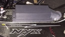
-removed the carbon fiber wrap from the controller.
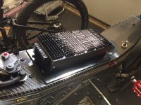
-removed the rubber mounts and swapped out with metal washers so the cover could act a heat sink.
-added small heat sinks to the top...(more on order for the sides)

Before

IMG_2777.JPG


After

IMG_2788.JPG


As soon as the battery is topped off, I will hit the trails again and report back.
 
Hi guys,

I am having some problems with my mini-e. I am getting a halls! error. I happened while I was riding and luckily I could continue my ride with sensorless mode.

I have tried it with several motors, so the problem has to be at the controller side.

I am measuring voltage which I think is correct. All the halls are about 4.5V and I am reading the same voltage with the positive(=red) wire.
When I look at the diagnose screen, I can see there is a correct voltage (4.5V), but nothing happens with the 1 and 0. All 3 of them are 1, and next H0. Nothing happens when I turn the wheel.

So: 111,H0 and C00.

What could it be? I checked the wires and replaced them with proper width. So I think it must be something within the controller??


Thanks,
Boestin
 
Update.

Just got back from a ride. Pushed it hard, lots of hills. Controller did not go into limp entire ride.

Thanks for all the help. I will add some more heat sinks to the sides, but other than that problem solved.

My only limiting factor now is motor temp.
 
joostj - Glad she's up and running again :D. Are you just using adheasive thermal pad to 'stick' the H/S's on or paste? One of my old computer builds I used a mineral oil bath as a lark with a de-lidded AMD and a tiny heatsink, worked a treat. Tempted, if you were frivolous to take the end caps from the controller, gasket it up and fill with mineral oil. It'll help saturate all that heat to any permanent cooling solution you come up with :twisted:.

BTW the FETS are on the thin side with the most screws (holding the FET H/S in place), just a heatsink there will probably sort your issue :). Also, although it looks bad ass :twisted: atm, some of the heatsinks are mounted counter airflow. For more efficent use of air cooling work with the flow :D.

Boestin - I'm a severe watchdog with faults, seems you have the 'R113 resistor error'. This is either a RMA or if your a tinker a quick couple of quid and a pair of tweezers for some soldering action within the display unit I believe.

I don't suppose you could give a bit more detail as to how it happened please :D? What speeds, nominal voltage, Amps set, maybe amps displayed, any indicators before hand? Regen? I've had this happen once and the cause was a combination of High speed, high amp draw and a loose connection to one of my motor hall sensors.
 
joostj - Glad she's up and running again :D. Are you just using adheasive thermal pad to 'stick' the H/S's on or paste? One of my old computer builds I used a mineral oil bath as a lark with a de-lidded AMD and a tiny heatsink, worked a treat. Tempted, if you were frivolous to take the end caps from the controller, gasket it up and fill with mineral oil. It'll help saturate all that heat to any permanent cooling solution you come up with :twisted:.

BTW the FETS are on the thin side with the most screws (holding the FET H/S in place), just a heatsink there will probably sort your issue :). Also, although it looks bad ass :twisted: atm, some of the heatsinks are mounted counter airflow. For more efficent use of air cooling work with the flow :D.

I don't think I have the guts to fill the controller with mineral oil.....but it's got me thinking...what would happen if we fill the hub motor half full of mineral oil? Ultimate cooling? probably something wrong with that I'm not thinking of.

The heat sinks are attached with thermal adhesive. I also have some thermal epoxy and will likely properly re-attach now that I know it works.

Thinking about epoxying some of these little heat sinks between the spokes of the motor. There is where I'm getting the most heat when hitting with a temp gun after a ride.
 
Boestin said:
Hi guys,

I am having some problems with my mini-e. I am getting a halls! error. I happened while I was riding and luckily I could continue my ride with sensorless mode.

I have tried it with several motors, so the problem has to be at the controller side.

I am measuring voltage which I think is correct. All the halls are about 4.5V and I am reading the same voltage with the positive(=red) wire.
When I look at the diagnose screen, I can see there is a correct voltage (4.5V), but nothing happens with the 1 and 0. All 3 of them are 1, and next H0. Nothing happens when I turn the wheel.

So: 111,H0 and C00.

What could it be? I checked the wires and replaced them with proper width. So I think it must be something within the controller??


Thanks,
Boestin

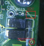
You can check the resistance of that resistor, will have to remove the coating they put over the resistor. If the resistance isn't around 4 ohm it is bad. Most likely it will read something in the thousand ohms meaning that the resistor is dead, this will be the same value once you completely remove the resistor. If you get no reading it means you are not making contact with the resistor and need to remove the protective coating.

it is somewhat a difficult resistor to replace because it is so tiny and they put that protective coating over the whole circuit board which has to be removed on the resistor. Order like 20+ of these resistors because they are so cheap and you will probably lose many when trying to replace it.

Here is where replacing this r113 resistor is discussed, and the posts after it.

https://endless-sphere.com/forums/viewtopic.php?p=943339#p943339

The replacement resistor is a SMD 3.9 ohm 1/10w 0603

Adaptto really should have made some kind of fuse or something easier to replace as I've blown this resistor twice already. Both because of where my wires exit the hub. Shorted temp wire to phase once, and a halls wire to phase another time.
 
joostj said:
joostj - Glad she's up and running again :D. Are you just using adheasive thermal pad to 'stick' the H/S's on or paste? One of my old computer builds I used a mineral oil bath as a lark with a de-lidded AMD and a tiny heatsink, worked a treat. Tempted, if you were frivolous to take the end caps from the controller, gasket it up and fill with mineral oil. It'll help saturate all that heat to any permanent cooling solution you come up with :twisted:.

BTW the FETS are on the thin side with the most screws (holding the FET H/S in place), just a heatsink there will probably sort your issue :). Also, although it looks bad ass :twisted: atm, some of the heatsinks are mounted counter airflow. For more efficent use of air cooling work with the flow :D.

I don't think I have the guts to fill the controller with mineral oil.....but it's got me thinking...what would happen if we fill the hub motor half full of mineral oil? Ultimate cooling? probably something wrong with that I'm not thinking of.

The heat sinks are attached with thermal adhesive. I also have some thermal epoxy and will likely properly re-attach now that I know it works.

Thinking about epoxying some of these little heat sinks between the spokes of the motor. There is where I'm getting the most heat when hitting with a temp gun after a ride.


For cooling the controller there are several options, to be tried separately or together. Large heat sink, easy and affordable. I see you have already done that. Nice. Is controller working great now or still in the need of more cooling?

Active cooling from small computer fans, alone or used with heat sink for even more effect. Or heat sink and water cooling, a little pump, reservoir and a radiator. If you look up oil cooling computers you will find various oil including baby oil will be non conductive and work well with all kinds of electric circuit boards etc.

There are a few that are running oil cooled hub motors. consensus seems to be that oil cooling is not worth the mess, with oil drippings, extra drag etc.
Oil cooling hub motors; https://endless-sphere.com/forums/viewtopic.php?f=2&t=37972

If you epoxy those heat sinks to the motor let us know how it turns out. Should work wonder with the ferrofluid.
 
For cooling the controller there are several options, to be tried separately or together. Large heat sink, easy and affordable. I see you have already done that. Nice. Is controller working great now or still in the need of more cooling?

Active cooling from small computer fans, alone or used with heat sink for even more effect. Or heat sink and water cooling, a little pump, reservoir and a radiator. If you look up oil cooling computers you will find various oil including baby oil will be non conductive and work well with all kinds of electric circuit boards etc.

There are a few that are running oil cooled hub motors. consensus seems to be that oil cooling is not worth the mess, with oil drippings, extra drag etc.
Oil cooling hub motors; viewtopic.php?f=2&t=37972

If you epoxy those heat sinks to the motor let us know how it turns out. Should work wonder with the ferrofluid.

The heat sinks on the controller seem to be working great. I have some larger ones coming that I will epoxy to the sides for better performance.

I plan on epoxying 20 little ones (ones currently mounted to the top on the controller), to the hottest part of the cover...between the spokes(close to the magnets). I'm not sure how it will perform since I seem to get reading at the cover 40deg c cooler than the reading at the coil sensor. Heat is not really transferring efficiently to the cover.
 
that can be a good thing in some ways, as the magnets will get damaged from too high temps coming from the windings
 
Offroader said:
Adaptto really should have made some kind of fuse or something easier to replace as I've blown this resistor twice already. Both because of where my wires exit the hub. Shorted temp wire to phase once, and a halls wire to phase another time.


Wow thanks for the detailed instructions! Glad to be here at ES.

So the 113? Well I thought of that too, but the voltage seems pretty much ok, around 4,5v.. Wasn't the voltage thing the indicator to replace the 113?

Thanks!!
 
Boestin - If you translate the page I linked and look for the user 'nevolshebnik' post before he shows pictures, it mentions (google tranlate...) he had water in his motor, which seemed to blow the R113, but give 4.73v permanently, checking the resistor is the first confidence check I'd do :D .

Find the reason why it blew in the first place, 'nevolshebnik', 'offroader' and 'myself' all had fault conditions which caused this 'Halls!!' fault. Be really nit picky, cuts in insulation, slight abrasions etc.. :D

joostj - This is purely opinion :) , when you look at cooling a hub motor for long term use without a direct stator waterblock the first thing to look at is how many Watts your motor dissipates as heat. This is where it get depressing or exciting depending on your wants and tinker skills.

For example: a PA 120.3 and with optium flow dissapate 530Watts. Now I'm sure someone can do the math, a motor kicking out 6kW+ will convert a large amount into heat, even a direct contant waterblock with a more thermal conductive nanofluid and artic silver paste to act a a heat transfer will stuggle to keep peak temperatures down. Fins stuck to an air heated hub cover would at best guestimation on the high side be 100W dissipation..to the covers. I'd personally look at a meatier motor or slow it down a little going up hills (less Amps) or mount your current motor into a smaller rim.

In my head it's like an ICE, buy a cheaper underpowered model and throw loads at it to get the same power as the higher model :D. Always people who do it though and sometimes they do it really well :D.
 
I swapped over my motor on my Fighter to my HS4080 the other day.
I managed to tune it better than my Leaf, and it seems to be working well with the Adaptto so far. To tune it I found the best way was to spin the motor up to max speed in boost mode, then adjust the Hall angle corr. and Ind timing's till it was smoothest and ran coolest off the ground.

Unfortunately however, something disconnected with my KTY84 temp sensor and it's not registering with the controller. I'm not going to open up the motor to fix the connection unless something else breaks as I also run a separate temp sensor with a display independently of my Adaptto which is still working fine.

I noticed that when I switched the temp sensor setting in the advanced menu to No...the controller now seems to be trying to predict the temperature of the motor and limiting power accordingly. Is that right?
The problem is though, it seems like it's estimates are way off and when set to 115C rollback, it starts limiting power at around 65C as displayed on my other temp sensor.
I raised the limit to 200C and that seems to have helped as it still doesn't limit power at 75C now, but I just wonder why it might be estimating it so wrong?
Any idea's?

Cheers
 
joostj said:
For cooling the controller there are several options, to be tried separately or together. Large heat sink, easy and affordable. I see you have already done that. Nice. Is controller working great now or still in the need of more cooling?

Active cooling from small computer fans, alone or used with heat sink for even more effect. Or heat sink and water cooling, a little pump, reservoir and a radiator. If you look up oil cooling computers you will find various oil including baby oil will be non conductive and work well with all kinds of electric circuit boards etc.

There are a few that are running oil cooled hub motors. consensus seems to be that oil cooling is not worth the mess, with oil drippings, extra drag etc.
Oil cooling hub motors; viewtopic.php?f=2&t=37972

If you epoxy those heat sinks to the motor let us know how it turns out. Should work wonder with the ferrofluid.

The heat sinks on the controller seem to be working great. I have some larger ones coming that I will epoxy to the sides for better performance.

I plan on epoxying 20 little ones (ones currently mounted to the top on the controller), to the hottest part of the cover...between the spokes(close to the magnets). I'm not sure how it will perform since I seem to get reading at the cover 40deg c cooler than the reading at the coil sensor. Heat is not really transferring efficiently to the cover.


With even more heat sinks you controller will stay cool even in summertime. Are you planning to secure those heat sinks with anything besides epoxy? I am thinking what if they break loose at speed?

Have you tried to add more then 5ml ferrofluid? Maybe you are a little below sweetspot for the QS motor? Just thinking out loud here, but could it be that the QS needs more FF then the mxus? wider stator etc.
 
Have you tried to add more then 5ml ferrofluid? Maybe you are a little below sweetspot for the QS motor? Just thinking out loud here, but could it be that the QS needs more FF then the mxus? wider stator etc.

Good point....guess it would hurt to throw the rest in there for 10cc total. It is one big motor.
 
Ok. The resistor did not gave me any readings.. I pushed it to hard and the bugger came off.
Look what I did :shock:
Should I fix the line? It seems to be going nowhere ...

Is this the right one to order? I didnt understand what 1/10w meant, but this seems to be ok.
http://www.reichelt.nl/SMD-0603-1-00-k-Ohm-8-20-k-Ohm/SMD-0603-3-9K/3/index.html?&ACTION=3&LA=5&ARTICLE=89437&GROUPID=4332&artnr=SMD-0603+3%2C9K
 

Attachments

  • Untitled.jpg
    Untitled.jpg
    49.1 KB · Views: 4,568
Your a few thou off...

by crea2k » Sat Sep 06, 2014 1:58 pm
I am told on the Russian forum that R113 is the common fault for this issue and "The value of the resistor is any within range 2-8 ohms" , I think I should have some SMT resistors in that value in my box and can use my hot air rework station to replace it in 5 mins, better get my "shoddy mechanical skills" ready for this too, as everyone with such mechanical skills owns hot air rework stations, oscilloscopes and boxes and boxes of microelectronic parts.....

Something more like this or this I believe 8).

As for the track damage, no idea sorry, thats an Adaptto Labs question unless someone has the circuit diagram for the screen?
 
Boestin said:
Ok. The resistor did not gave me any readings.. I pushed it to hard and the bugger came off.
Look what I did :shock:
Should I fix the line? It seems to be going nowhere ...

Is this the right one to order? I didnt understand what 1/10w meant, but this seems to be ok.
http://www.reichelt.nl/SMD-0603-1-00-k-Ohm-8-20-k-Ohm/SMD-0603-3-9K/3/index.html?&ACTION=3&LA=5&ARTICLE=89437&GROUPID=4332&artnr=SMD-0603+3%2C9K

Damn, if you cut that trace you probably need to build that trace back again. You can use 90%+ isopropyl alcohol to remove the varnish/protective coating.
That trace may connect to something on the other side of the board?, but I can't be certain you would have to check. You may have just scratched the varnish they put over everything and not damaged the trace?


I don't get how you don't have readings, even with the resistor removed you should read a very high ohms number where the resistor attaches. Are you using the ohm setting on your multimeter?

Do you still have the resistor that was removed? Can you check the ohms with it off the circuit board?

I believe that 0603 resistor you linked is the right one, Probably all 0603 are 1/10w. On the specs of your linked resistor it says power Loss 100 mW, which is 1/10 w. Maybe that is the same value they are referring to.

That resistor basically is there as a fuse, so you want to get the right size and wattage rating so it works properly as a fuse.

You're going to have to try and be more careful when soldering this if you have no experience, you should get some old scrap electronics that have these SMD chips on them (mostly all have them) and practice soldering and removing them before you attempt doing it on the Max-E. Watch some you tube videos also.
 
Sorry, Offroader maybe it's me, but isn't his link for a 3.9Kohm not 3.9ohm.

Boestin - Does your Fluke/Multimeter indicate '-' for open circuit? For the damaged track if you want a quick repair the Silver Conductive Pen method works they even have a youtube nowadays.

[youtube]WY3d8N21OAE[/youtube]
 
ccmdr said:
Sorry, Offroader maybe it's me, but isn't his link for a 3.9Kohm not 3.9ohm.

Boestin - Does your Fluke/Multimeter indicate '-' for open circuit? For the damaged track if you want a quick repair the Silver Conductive Pen method works they even have a youtube nowadays.

Yes you are correct that is a 3.9K and will not work. You need 3.9 ohm.

However, crea2k said you can use anything between 2-8 ohms, if you can't find a 3.9 ohms locally and don't want to wait.
 
Guys, thanks all for your help!!

About the resistor, I'll search locally here.. but before I will check here again if its correct. A few thousands off :D Well there goes my repuptation :oops:

@ccmdr I couldn't find the pinched out R113, so I can't check it anymore. It has to be replaced anyhow. I measured with my Fluke other resistors (not on the Adaptto board) and it seems to work ok.

So about the whole reason how I got the Halls! error:
When looking at the phase and halls exit at the motor side, I could see that there was damage at the phase section. Not the halls though, it seems in mint condition. Edit: so this could initiated the R113 issue.

When I opened the halls connector at the controller side, there was a wire loose. First I thought that was the issue, so I fixed that, but unfort. that wasnt the case.


Let me go back in time. This is the third time the this controller broke down, you can check a couple of pages back, I can post mailings here if needed.
I have a max-e and a mini-e. The Max seems to hang in there and does not brake that easily. The mini's however, hm. I have sent them twice now to Adaptto, which costed me about 250 euros in total.

The last time I sent the controller was resulting in a not so good experience with Adaptto. In a nutshell Adaptto claimed that it broke down due to water in the controller, but they "forgot" to take a picture. I had my doubts about that and didn't agree with them at first. Anyway, I wanted a working controller back, so I payed.
Now, It is this same controller that give me the Halls! error. The reason for me to open the case, was also to check it there was water trails/damage to be seen. I can't find that at all! Therefore Adaptto lost their trust with me. Not saying that they make shitty stuff. In the contrary they make beautiful stuff. It's just that there customer approach makes me sick: I mailed them that the hall wire at the controller side was loose. All of a sudden they said to my to NEVER do that and that I should have taken pictures....while they did not take pictures of the so called "water damage" Anyway, I opened the case to prove that there was not any water damage in the first place.
 
Boestin said:
Guys, thanks all for your help!!

About the resistor, I'll search locally here.. but before I will check here again if its correct. A few thousands off :D Well there goes my repuptation :oops:

@ccmdr I couldn't find the pinched out R113, so I can't check it anymore. It has to be replaced anyhow. I measured with my Fluke other resistors (not on the Adaptto board) and it seems to work ok.

So about the whole reason how I got the Halls! error:
When looking at the phase and halls exit at the motor side, I could see that there was damage at the phase section. Not the halls though, it seems in mint condition. Edit: so this could initiated the R113 issue.

When I opened the halls connector at the controller side, there was a wire loose. First I thought that was the issue, so I fixed that, but unfort. that wasnt the case.


Let me go back in time. This is the third time the this controller broke down, you can check a couple of pages back, I can post mailings here if needed.
I have a max-e and a mini-e. The Max seems to hang in there and does not brake that easily. The mini's however, hm. I have sent them twice now to Adaptto, which costed me about 250 euros in total.

The last time I sent the controller was resulting in a not so good experience with Adaptto. In a nutshell Adaptto claimed that it broke down due to water in the controller, but they "forgot" to take a picture. I had my doubts about that and didn't agree with them at first. Anyway, I wanted a working controller back, so I payed.
Now, It is this same controller that give me the Halls! error. The reason for me to open the case, was also to check it there was water trails/damage to be seen. I can't find that at all! Therefore Adaptto lost their trust with me. Not saying that they make shitty stuff. In the contrary they make beautiful stuff. It's just that there customer approach makes me sick: I mailed them that the hall wire at the controller side was loose. All of a sudden they said to my to NEVER do that and that I should have taken pictures....while they did not take pictures of the so called "water damage" Anyway, I opened the case to prove that there was not any water damage in the first place.

Damage to just the phase wire won't break the r113 resistor.

If there was a loose halls wire inside the controller that could have done it, but reconnecting it again won't fix the controller until you replace that resistor.

Is your controller out of warranty? Adaptto seems very good with repairing the controllers for free and free return shipping during their warranty period even if it was your fault.
 
Back
Top