Excerpt from: Unofficial English User Guide (translated from Russian version):
1.0 - Quick Start
Warnings!
• Motor or regenerative braking can not be used as the primary method of braking. Installation of standard brakes that ensure emergency stops is mandatory.
• Controller must not be operated without using over-current protection. Protection can be a fuse or circuit breaker. Fuse or circuit breaker must trip when peak current exceeds 250A for MINI-E and 400A for MAX-E. Note that the peak current is higher than the rated current. For example, a setup with a 65A rated current was treated with a peak current of about 200A.
• Controller is built to environmental protection standard IP54. This means that the controller can tolerate splashing water. Nevertheless bear in mind that when driving in the rain at high speed, water (for example, from the wheels) and drips at high speeds acts like a pressurized water stream, more than a splash. Therefore, do not operate the controller without additional protection when driving in rain or through puddles.
• Input voltage to the controller above 98VDC is prohibited. If you want more power (more than 70 amps of phase-current), do not use a battery that is more than 90VDC.
• Recommended battery voltage for maximum power is 85VDC.
1.1.1 - Key capabilities of the controller
• Three fully customizable power profiles including Regenerative braking
• Built-in power meter with a variety of information displayed
• Integration with optional BMS, and/or a second controller, and digital throttle
• DC-DC converter and USB connectivity to most smartphones
• Settings for throttle linearity and progression for smooth power
• Ability to connect virtually any source in DC Charging mode
• Capability to use the controller as a DC power supply
• Security- lock controller using a password
• Ability to program the required distance to go and power to use for a given trip. The controller will automatically limit the power and maximum speed as necessary to reach your destination.
• Display the voltage of each battery cell or parallel bank connected to the optional Adaptto BMS
• Ability to continue to operate with a faulty Hall sensor in motor
1.1.2 - Package Contents
Controller unit 1 piece
Display module 1 piece
Operators guide 1 piece
Installation kit 1 piece
Contact connector XT150 Female, 2 pcs
Contact Connector XT150 Male, 3 pcs
Insulator connector XT150 Female, black, 1 pc
Insulator connector XT150 Female, red, 1 pc
Insulator connector XT150 Male, blue, 3 pcs
Miniature connector for the throttle cable and brake switches to the Display Module 1pc
Thermocouple 1pc
Jack for Hall sensors 1 pc
Fastening clamps, Display Module 2 pcs
Display long mounting screws 2 pcs
Display short mounting screws 2 pcs
Display mounting nuts 4 pcs
Hex wrench 1 pc
1.1.3 - Connections
Display Connection
Connect the long cable with the 4 pin blue connector to the display according to the connection diagram
Throttle and Brake Connections
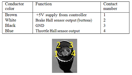
To work correctly you need to solder the throttle cable conductors to the corresponding wire mating connector (see table below). To use regenerative braking connect the brake handle sensors. In the case of using a brake handle button (switch) instead of Hall sensor, connect one switch contact to the brake sensor output, second to +5 V.
Fig. 1.2: Throttle cable connector pinout
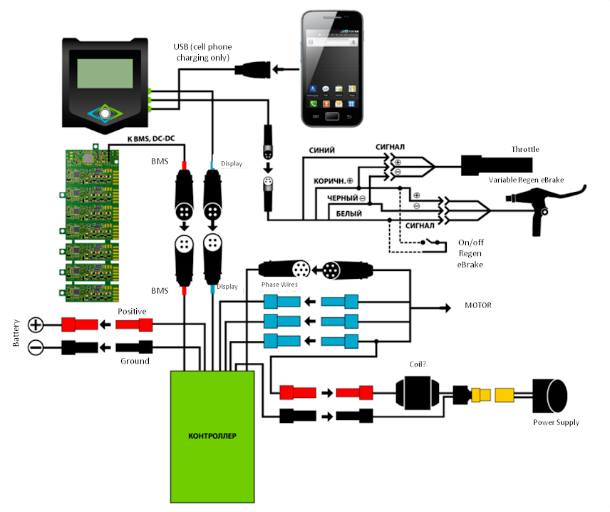
System Connections - Figure 1.1
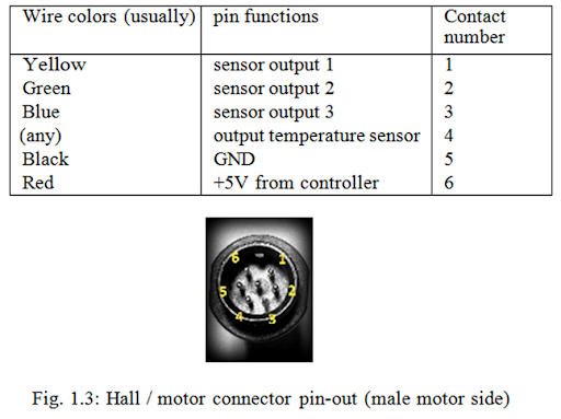
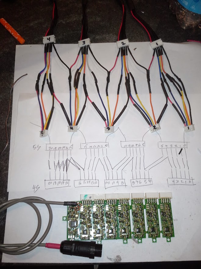
Connecting Motor Hall Sensors
Solder motor Hall sensor wires to the connector pins according to the table. Traditionally IME motors use standard color-coded wires as shown below. However there are motors with different color markings. Match circuits as shown in the table. Incorrect wiring can damage the Hall sensors.
Phase Conductors Connection
Install 3 blue XT150 male insulators on the motor phase conductors and solder three XT150 male pins to the phase conductors. Connect them to the blue XT150 connectors on the controller. Any combination is OK. No matching is required.
Power Connection
Solder the black XT150 female connector to negative battery lead, and the red XT150 female connector to battery positive. We strongly recommend using a current limiting device in the power supply circuit. For MINI-E it is recommended to install one fuse or circuit breaker at the peak (not continuous) current rating. For the MAX-E is advisable to install two parallel overcurrent devices.
Example: to provide 400A peak current protection, install (2) 200A fast acting fuses in parallel.
Connecting the charger to the controller
Connect the charger to the controller as shown in Figure 1.1
Connect the black connector of the charging coil to the controller black wire.
Connect the red connector of the charging coil by splicing the red wire to any phase conductor. The controller phase wires must stay connected to the motor. Connect the charger/power supply to the supplied XT90 connector, being careful of the polarity.
Connect the charger to the mains power when ready to start charging.
Instructions for configuring the controller when charging is in Section 3.3.6
Important! When a charger is connected, do not press the throttle and (or) the brakes. This may result in equipment damage.
1.1.4 Quick Setup
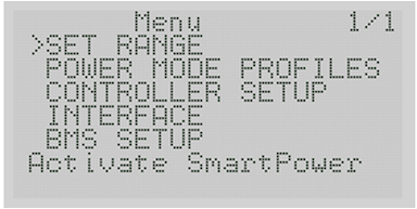
After connecting the battery you will see the main screen. In order to get to the main menu you have to press the “Down” button. If you have activated the quick menu and press "Down" again, you will access the main menu (Screen 1.4)
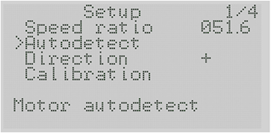
Fig. 1.4: Main menu
First, make sure that the correct settings for upper cutoff and lower cutoff voltages are shown on the display for your battery. They are in the BMS Setup 3.5 If BMS is installed, proceed with BMS Setup using the down button and press the Right button to enter the menu.
Set lower threshold (discharge) voltage cutoff and the upper threshold high voltage cutoff in accordance with the minimum and maximum voltage of your battery. In order for regenerative braking function to work with a fully charged battery, upper threshold voltage can be set slightly higher. Controller Setup menu 3.3.1 is necessary to configure the following settings:
Speed Coefficient <Speed Ratio> to match your motor/ rim/ tire combination.
This value is given in millimeters per electrical revolution. To calculate the required value must be the circumference of the wheel assembly divided by the number of pole-pairs in your motor.
For most direct-drive motors the number of pole-pairs is equal to 23. If possible, verify the data for your motor. For example, for a 9 Continent motor, 24" rim with a 2.5” tire the value will be 1965mm/23 = 85.4mm
The next step is to perform the Autodetect procedure. See Section 3.3.2
Fig. 1.5: The Setup Menu
Danger! The wheel must be securely raised off the ground and free to rotate during auto-detection!!!
Select <Autodetect> (autodetect) menu by pressing the "Right” button, then slowly open the throttle control to the maximum position. Be careful, the wheel can rotate in the opposite direction, causing rotation of the crankset and pedals. If you noticed that the wheel begins to spin in the opposite direction, immediately release the throttle. Change the direction of rotation option <Direction> (direction) and repeat the Autodetect procedure.
The full auto detection cycle takes 2-3 minutes. The wheel will rotate slowly at first (about 2/3 of the cycle) and then quickly the rest of the time.
Please remember: In order to Autodetect the correct timing angles, the wheel must rotae freely during the entire cycle.
If Autodetection is successful, you will see the message <Successful>.
This means that auto detection is completed and you can let go of the throttle.
If an error message is displayed:
• <Interrupted By thr> (interrupted throttle) indicates the throttle was released before the auto-detection cycle was completed.
• <Halls Error> problem with the Hall sensors
• <Interrupted By key> if you press any button during the cycle
• <Unknown error> other errors.
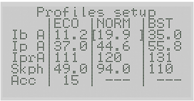
Fig. 1.6 Profiler
Set the current limit profiles using the menu
<POWER MODE PROFILES> 3.2 (Found in the main menu):
• Ib A - battery current limit in amps
• Ip A - phase current limit in amps
• Ipr A - regenerative braking phase current limit in amps
• Skph - maximum speed limit in kmh or mph.
Note: Speed Units are set in the menu item <INTERFACE>3.4
• Acc - acceleration limiting. This dimension is an abstract value. Increasing the number increases the acceleration.
Installing Adaptto BMS 3.5 (Battery Monitoring System)
Even if the Adaptto BMS module is not connected (or disabled), you need to set the battery capacity and the lower and upper voltage cutoff limits.
You should specify the capacity of the battery in amp-hours and watt-hours for the correct operation of the power meter. These values can be changed automatically during a full discharge cycle.
Setting regenerative braking 3.3.5
When using the brake lever with a Hall sensor it is sufficient to specify the maximum battery voltage and maximum battery inrush current during regenerative braking.
Brake handle signal can be inverted <Inversion> if required.
When using reed switches, enabling the soft-start recovery <Smooth> option is recommended. This will reduce stress on the dropouts.
Calibration of throttle / brake controls
Calibration of controls is in the menu: Controller setup-> Calibration> <Thr Limits> 3.3.4
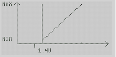
Fig. 1.7: Calibration
After setting the throttle limits, configure the linearity of the throttle (optional <Thr linear>), especially if you are using a Hall sensor type throttle control.
When you select this option, twist the throttle control fully 4 times, one after the other as uniformly as possible for 2-3 seconds each time. Cycles longer than 3 seconds or shorter than 2 seconds will be ignored. After each successful motion you will see the curve of the signal output of your throttle.
After the 4th time calibration is complete and the throttle control will work linearly.
If you require a progressive type throttle, change the value in
<thr progr.> from 0 to 1-3 to suit your needs.
After calibration of the throttle select <Brk limits>. Calibration of the brake sensor/switch is similar to the throttle limits procedure.
Congratulations, your controller is ready to use!

")