
You are using an out of date browser. It may not display this or other websites correctly.
You should upgrade or use an alternative browser.
You should upgrade or use an alternative browser.
Adaptto Mini-E/Max-E Owner's Thread
- Thread starter GCinDC
- Start date
anttipaa said:Just trying to wire max-e and cromotor for my first build. Everything else seems to work fine but temp stays in zero. I have cromotor v3 with ntc10k sensor. I soldered temp sensor wires to pins 4 and 5. Should it show 0 until temp rises over 29?
no, it should show 29°C or above. i do not know the pinout by heart, but the second pin belongs to GND as i can remember..
I'd really like to know how hard the Max-E can be pushed before stuff starts popping. Has anyone here gone beyond the factory max values? I was considering liquid cooling the FETs if it means I can get more juice out of it. I'm fairly light, so my Cromotor still doesn't get hot even with every power setting maxed out.
I'm riding greyborg with lowered front fork and clip-on bars in more aggressive stance to keep the front-end down. Current top speed at 18s is a consistent 85-86kph (with accurately measured 17" rear and Michelin M45 2.75"). Acceleration is really good, but still feels too easy to control. It needs more crazy.
I'm riding greyborg with lowered front fork and clip-on bars in more aggressive stance to keep the front-end down. Current top speed at 18s is a consistent 85-86kph (with accurately measured 17" rear and Michelin M45 2.75"). Acceleration is really good, but still feels too easy to control. It needs more crazy.
GCinDC
100 MW
what are the max values (batt/phase A) for the max-e? have you upped OVS to the max?trevc2 said:Has anyone here gone beyond the factory max values?
why not add 4s packs to get to 22s?
finally, it may be worth it for you to go back to rc7 - madin88 reports higher acceleration w/ this F/W, and it's prob the same as my rc4 version.
is controller heat limiting your current? i've been wondering how hard it would be just to drill a hole through the fet seperator bar and pumping a liquid through. of course it probably makes sense to build a whole new enclosure... i'd love to see designs that folks have in mind, either to improve air cooling or active cooling... i'd rather not load her up w/ mineral oil, for leakage concerns and maintenance purposes, but it's a thought..
Interesting about the firmware, thanks for letting me know.
OVS is maxed, with a speed limit of 110kph set in case I'm spinning the wheel without load. Battery and phase values are maxed, but I can't recall their values. I'll check that soon. I seem to recall the FET temp values were all pretty low, the controller never goes beyond "a bit warm" to the touch (very scientifical, I know)") I was curious about other components that could be at risk if the amps are cranked up.
I was curious about other components that could be at risk if the amps are cranked up.
It's surprising that more people haven't tweaked these things.
I'm only running a temporary battery pack, which is simply 3 8ah Nanotechs in series. It doesn't go far, but also doesn't seem to be a limiting factor in output.
Can Max-E still do full phase + battery amps on 22s, wasn't 85v where it started limiting things? I hope I'm wrong.
[youtube]QnaurCW-oj8[/youtube]
OVS is maxed, with a speed limit of 110kph set in case I'm spinning the wheel without load. Battery and phase values are maxed, but I can't recall their values. I'll check that soon. I seem to recall the FET temp values were all pretty low, the controller never goes beyond "a bit warm" to the touch (very scientifical, I know)
I was curious about other components that could be at risk if the amps are cranked up.It's surprising that more people haven't tweaked these things.
I'm only running a temporary battery pack, which is simply 3 8ah Nanotechs in series. It doesn't go far, but also doesn't seem to be a limiting factor in output.
Can Max-E still do full phase + battery amps on 22s, wasn't 85v where it started limiting things? I hope I'm wrong.
[youtube]QnaurCW-oj8[/youtube]
GCinDC said:what are the max values (batt/phase A) for the max-e? have you upped OVS to the max?trevc2 said:Has anyone here gone beyond the factory max values?
why not add 4s packs to get to 22s?
finally, it may be worth it for you to go back to rc7 - madin88 reports higher acceleration w/ this F/W, and it's prob the same as my rc4 version.
is controller heat limiting your current? i've been wondering how hard it would be just to drill a hole through the fet seperator bar and pumping a liquid through. of course it probably makes sense to build a whole new enclosure... i'd love to see designs that folks have in mind, either to improve air cooling or active cooling... i'd rather not load her up w/ mineral oil, for leakage concerns and maintenance purposes, but it's a thought..
GCinDC
100 MW
i think we're good up to 92v to run max settings in locked mode.
max voltage was discussed in for sale thread (and rather than searching through russian forum myself, i'm inclined to trust him!
ps, from adaptto specs... 98V max

max voltage was discussed in for sale thread (and rather than searching through russian forum myself, i'm inclined to trust him!
Falco said:There was alot of discussion about doing this on the russian forum and they said if there was demand for it they would do it but it came back to whats the point? This controller uses flux weakening which can net you 30% more motor speed. running one of these on 18s gives you the same top speeds as running on 24s lipo on a controller that doesnt have this feature. There is also current limiting software on this controller. At 92 volts the limiting starts and cuts all power to the motor above 98v. These controllers are sold with a warrenty. If you want to push them to the edge of what they can do then you just load the unlocked firmware and take matters into your own hands.zombiess said:Can you switch over to 150v rated components? Running at max spec is unacceptable. Are you planning to build a version capable of running 24s LiPo?
ps, from adaptto specs... 98V max
Mammalian04
100 kW
Hey guys,
I am trying to figure out how I can build a battery pack in two pieces (something like 20s6p - 20s6p) and use them in two bikes for now. When I get more cash (or a new battery strikes my fancy) I can combine the batteries in one bike and get a whole new set for the other. A complication is that "I think" I need to keep things in 4s groups for the adaptto BMS. I am drawing up the revised battery layout and connectors. I will post up in a bit when I get further along.
The real reason for this post is for people looking to understand balance wires. I am a total noob and this site broke it down for me pretty well. Check it out if you need the BEGINNER intro. http://www.tjinguytech.com/charging-how-tos/balance-connectors
I think the Adaptto uses the JST-XH balance connectors. Does that sound right?
GCinDC
100 MW
yes, the adaptto BMS accepts jst-xh connectors... can't recall which end is male or which is female.Mammalian04 said:the Adaptto uses the JST-XH balance connectors. Does that sound right?

but the balance connector coming off a a typical turnigy or zippy 4s pack from HK fits perfectly, though you'll most likely be paralleling and extending it..
if you have 2x 20s6p packs, you could simply parallel the main leads if they're at the same voltage, and thereby double your capacity (and making the pack 20s12p). and if each parallel balance wire extension had 6 extra connectors per pack, you could theoretically attach them, but i gotta wonder about your overall design - a discussion for another thread, perhaps?
Mammalian04
100 kW
GCinDC said:... i gotta wonder about your overall design - a discussion for another thread, perhaps?
GC, to keep from digressing too much from Adaptto specifics in this thread, I have posted my response in my build thread here: Full Suspension eBike Build Thread.
finally started getting my wiring together. still waiting on money for my battery, so it doesnt go anywhere yet.
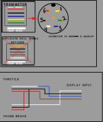
I've set up a thumb throttle on the left bar to use for regen braking. Will see how it works. The way my brakes sit makes it fit in a slightly awkward spot, but I'll need to ride it to confirm that.
didnt see this thread when I posted a question in my own. Basically I photoshopped up my understanding of my hall connections (cromotor v3 running to a mini-e), figured others could use it. If I've messed it up, someone let me know and I'll take it down to not confuse anyone.
Attachments
madin88 said:for cromotor try:
ind timing: 430µs
angle corr: 2,8°
PWR timing 1,4
hall offset: 60°
OVS: 2-3 for topspeed like trapezoidal controller
please reply how it works
I did get from autodetect:
Angle corr: -1.59
Ind timing: 558µs
PWR timing: +1.4
PWR timing 2: +1.4
Hall offset :240°
Hall reverse: yes
Wire reverse: yes
Wire r,mOhm: 083
Motor KV: 06635
Wire R PHC: Yes
I must say I dont really understand meaning of those values. I cant try exactly same values that you suggested because controller wont allow that. Is there something wrong..?
Allex
100 MW
No, nothing is wrong, it is fully normal.
Flash your unit with latest v9 firmware. Autodetect is more accurate there.
Angle corr: -1.59
Ind timing: 558µs
PWR timing
Those are your main values you should look into and tune. see:
http://endless-sphere.com/forums/viewtopic.php?f=6&t=27911&start=175#p918729
Flash your unit with latest v9 firmware. Autodetect is more accurate there.
Angle corr: -1.59
Ind timing: 558µs
PWR timing
Those are your main values you should look into and tune. see:
http://endless-sphere.com/forums/viewtopic.php?f=6&t=27911&start=175#p918729
Allex
100 MW
If you want a crazy wheelie machine wich will punch at initial start, similar to an Infinion. Just adjust your throttle curves:
You can start going from 3,5V to 2,5V or down to 2.0V - but be warned! Your bike will be much more agressive now.
Controller Setup->Calibration->Throttle limits.

You can start going from 3,5V to 2,5V or down to 2.0V - but be warned! Your bike will be much more agressive now.
Controller Setup->Calibration->Throttle limits.
What wire do I put my ignition key switch in to turn off the display but keep the security enabled ?, also is there a wire that turns everything off too , well other than pulling the main breaker, like a switched relay for the controller ?.
Hugechainring
100 W
I don't believe that is possible, exactly. I'm pretty sure the current firmware allows the the controller to go into "sleep" mode while the security features are enabled, saving power by turning off the display, but the main power would still need to be "on".
The only way you will be able to use a key switch is combined with a contactor or solid state relay as you mentioned. You would need to add this device, and wire the keyswitch into the contactor coil circuit. A standard key switch isn't rated for the controller input current.
The only way you will be able to use a key switch is combined with a contactor or solid state relay as you mentioned. You would need to add this device, and wire the keyswitch into the contactor coil circuit. A standard key switch isn't rated for the controller input current.
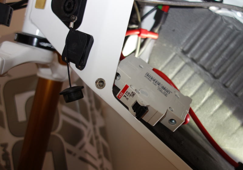
I have solved the all off power problem I think , I'm going to mount the breaker and cut a hole in the top of the battery box and mount it with a rubber cap like this : http://www.emodels.co.uk/plastic-kits/rubber-switch-cover-101453-p-37041.html
Mammalian04
100 kW
Just be sure to hide it well. If the power is killed, so is the wheel lock.
I am thinking about the same thing but putting the breaker on the inside. The get a metal shop to make me some piano hinge doors and a lock for one of the side covers. If I don't load up pull with batteries, I can make a little tool bag to put in there and also get to the breaker. That is definitely a winter project though.
Of course the breaker needs to be designed for cycling on and off. Cycling a bunch will eventually weaken and kill a normal residential breaker.
GCinDC
100 MW
i wired a breaker in, so it's easy to kill power to the system, but i only turn it on after starting the precharge circuit on the momentary switch:

i can use the breaker w/o the momentary switch, but it was designed for 300A at 12V i think, so the arcing at 80V will ruin the contacts eventually..
i do believe it's possible to put a switch on the positive wire to the display, but i don't know if it shuts the system down.
my understanding is the antitheft feature only works while the system is on, not when it goes into suspend mode. there was a fix related to this in the last firmware i think. could be wrong, but think if you want antitheft, the system as to be on. menu passwords help prevent throttle input..
Allex
100 MW
You can do like this to shut down your breaker remotley
[youtube]2Vi3byoakFk[/youtube]
If you want to power off the display you can place a switch on the red wire going to display, but then, like GC said, the antitheft wont work.
BTW, you want a simple and reliable solution(Adapttos recommendation) just install a regular apartment breaker, I use C63A, it angages at about 135 DC Amps for me and you can use whatever battery voltage.
And you can say goodbye to all prechargers, no need them anymore!
http://www.abb.com/product/seitp329/49a79353b0194401c12572ab00257544.aspx?tabKey=2&gid=ABB2CDS251001R0634&cid=9AAC100489
Last thing. Latest firmware has a speed limit of 90km/h, so forget about that one if you want to break some speed records. They will probably fix it in the next version.
Similar threads
- Replies
- 3
- Views
- 1,052
- Replies
- 85
- Views
- 7,305
- Replies
- 5
- Views
- 1,757