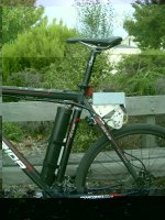
An Advanced Friction Drive System

EVTodd said:
Just use the brake to create a load. That's what I did when I made my video (which reminds me, I never did repost that video)..


Too easy. Thanks for that.

EVTodd said:
I think what most people don't understand is that with a system like this you rarely have the motor fully engaged. When I go full throttle the motor slides back into the tire and then backs off depending on the load (even at full throttle). If I'm going up a very steep hill then yes, it is fully engaged but 95% of the time it doesn't have much pressure on the tire at all.

I think my setup tends to hit the stopper at at around 50% throttle but its hard to tell when riding.

I did some more testing last night. Put through 2 more packs. The drive worked perfectly with the engagement and disengagement operating exactly as I hoped. The actual acceleration and speed is actually far better then I expected also with the bike hitting 60 kph on a few runs. Motor and ESC temps are also very acceptable. It sure isnt stealth though. Sounds like the bike has a turbine fitted especially at full throttle. Very cool stuff. :mrgreen:
 
Yeah, my stealth factor went down a bit when I switched to an rc motor but it was worth it! When I have my panniers covering everything you can't hear it as much but you can still tell there's something goin' on in there :lol: .
 
Since I just finished building my bike I think this is a great system to try and replicate rather than a few other options I've been considering. It'll be easy to remove if I want to just ride and give me help when I need it but just be a few extra lbs when I don't and I'll be able to use it on the wheels I have on any bike I have :D
I was thinking a bit lower speed but higher torque motor. Course that might not be what a friction drive such as this one is best at since it may just slip more on the tire or does it really stick to it well?
 
I think most of us can build one based on the angles you need and over center positions. If you can post this data, it would help us start on the design. It would be too hard to build a universal one since bike frames vary considerably and the place you have it mounted to isn’t going to be the same on each bike. I plan to use this light weight setup on a road bike. I think that would be a great solution for such a bike since it’s already efficient to pedal, adding the least amount of weight should make it even more practical and have it more as an assist. It's going to be interesting to see what others create based on your original design.
 
I've been looking at my folding 9FS (full suspension) and I have figured a way to mimic your mount within the rear swingarm instad of the rear triangle... I had to guess at the dimensions based on known motor diameter but all in all it looks as if it would be a no hassle way to reduce the weight of my current electric by 10lbs or more so I am very interested in attempting to reproduce this.

Have you given any more though to a Motor Can cover or tube of some sort? I have thought about it a bit and though this may seem idiotic to many, what about creating an aluminum pulley to encase the motor casing ? Set screws could be used to anchor it if need be, or magnet epoxy (making it a bit difficult to remove if needed). But having a pulley shaped sleeve with proper bore for the motor would help strengthen the case considerably.

Do you know if the motor is terminated Delta or Wye?

I may give a similar system a shot (though I will probably prototype with wood) using a tower pro 5330 (replaced bearings already and glued the magnets down), I will be driving a 20" wheel so the increased Motor Case diameter shouldn't effect me too much...

Thanks and nice work again!

-Mike
 
That's an amazing design. Ever think of building and sell these units on here?
 
mwkeefer said:
I've been looking at my folding 9FS (full suspension) and I have figured a way to mimic your mount within the rear swingarm instad of the rear triangle... I had to guess at the dimensions based on known motor diameter but all in all it looks as if it would be a no hassle way to reduce the weight of my current electric by 10lbs or more so I am very interested in attempting to reproduce this.

Have you given any more though to a Motor Can cover or tube of some sort? I have thought about it a bit and though this may seem idiotic to many, what about creating an aluminum pulley to encase the motor casing ? Set screws could be used to anchor it if need be, or magnet epoxy (making it a bit difficult to remove if needed). But having a pulley shaped sleeve with proper bore for the motor would help strengthen the case considerably.
So this would be a primary drive rather then a friction drive? Might be difficult to get a good ratio without going dual reduction though. Worth some further investigation
mwkeefer said:
Do you know if the motor is terminated Delta or Wye?
What ever a standard RC motor comes with. This is a 3 wire motor so its can't be changed externally.
mwkeefer said:
I may give a similar system a shot (though I will probably prototype with wood) using a tower pro 5330 (replaced bearings already and glued the magnets down), I will be driving a 20" wheel so the increased Motor Case diameter shouldn't effect me too much...

Thanks and nice work again!

-Mike
Look forward to see what you come up with :)
 
After being away for a week I was keen to give the drive a good run. Took the bike on a 40km ride this morning. Good variety of roads, bike paths and plenty of hills. Took 2 x 5000 mah packs fitted into a PVC tube and connected one pack at the time. I have a cycle analyst fitted to the bike so I could keep good track of what was going on. Bike typically needs around 500 Watts to maintain 35kph. Rode the bike reasonably quickly typically traveling around the 30 kph mark. I then used the assist to maintain 30kph up any hills I encountered. This was a good pace ride that was enough to be quite a reasonable workout. Managed to only use 2.2 ah for the first 20km but the return trip was more uphill and I was letting the drive do a fair bit more of the work including a couple of long steady hills. Ended up using a total of 7ah for the ride. Ran it up to 1200 Watts a few times but in general, the duty was quite light. Motor and ESC came back cool at the end of the ride and no visible wear could be seen on the motor can.

One small issue I have noticed is that the lightly sprung pivot bounces against the tire over bumps and spins up the motor a little. However, you dont feel any drag and on normal made roads, it stays clear of tire without an issue. Working on a video at the moment and will post it soon.
 

Attachments

  • IMGP4719.JPG
    IMGP4719.JPG
    119.8 KB · Views: 3,473
Managed to put together a short video of the drive in action. Its a little hard to demonstrate as the drive needs load to climb the tire. I just used the brake as suggested by EVTodd. Once it locks in, the drive is very positive.

[youtube]61sM9qovORU[/youtube]
 
That bike looks really great and very stealth!
 
Very nice! My second build used a near identical method of driving the tire via the outrunner's can. I got a ton of heat on my system however, and used a bike shock to keep the motor engaged.
 
Absolutely brilliant , my hat goes off to you sir! The simplicity and low part count make this so successful.

+1 for friction drive RC!

John,
Maybe your heat came from too much pressure? A bike shock seems a little too much for such a setup.
 
Great stuff! I even like the way it looks on the bike. It would almost be a shame to hide it.

I agree with etard, heat shouldn't be a big issue with a friction system. People tend to put way too much pressure on the roller and tire. I've never had a heat issue and I can pull wheelies with my setup.

Kepler, are you thinking about trying a knurled sleeve over the motor? I know heat isn't an issue with your setup either but you could probably use even less pressure (and movement) if you did.
 
I've got no intention to hide the drive. Just plan to anodize all the aluminium parts black. The Electronics cover is now painted mat black which looks heaps better.

Funny you mention the sleeve addition. I agree that less tension would be an improvment as this setup needs very solid contact to avoid slippage. The motor isnt getting too hot though, I am more interested in improving efficiency. I also want to stick with the 1.3" slick tire.

I have now added a bike tube sleeve stretched around the can, raised the drive by 2mm, and extended the stop cable by 5mm to allow the over centre lock to engage more positivily. This has smoothed out the action of the drive quite a a bit and reduced power consuption by around 150 Watts on average. I am getting a slight bit of slipage at full throttle but I have also increased the power to 1800 Watts. I think I will current limit it back to 1200 Watts as this is plenty.

After 20km of testing, the tube over the can has worn a bit but I think thats only due to the extra power I have been putting through it. Either way, it takes only a few minutes to replace the sleeve if I need to. I would prefer the tube sleeve to be sacrificial rather then the tire anyway. Good thing about the tire tube sleeve is that it doesn't need to be glued to the can so its nice an easy to work with.

I plan to also experiment with a knurled sleeve but I need to purchase a knurling tool for my lathe first.
 
Kepler said:
I plan to also experiment with a knurled sleeve but I need to purchase a knurling tool for my lathe first.

I would make it a straight knurl, rather than a diamond pattern. You might even get more grip than a knurl, by using a coarse abrasive in the axial direction?

Nice design.

It's great to see so many different ideas being explored and documented on the forum :D
 
Yes.

No, you can use a knurling tool to do this.

See:
http://www.roto-finish.com/pdfs/PB-7007%20gate%20shaft.pdf
http://www.accu-trak.com/holders_cuttype/orissetup.html
 
Miles said:
You'd be reducing the contact area further, to no advantage, by using a diamond pattern.

I kind of doubt a diamond pattern reduces the contact area by that much. When the roller is engaged to the tire it's pushed into the rubber somewhat. I don't think it's an issue.

As we've discussed before, I have tried a straight knurl in the past and I've found that with a diamond knurl the roller is less likely to walk off the tire. Granted, it doesn't matter that much on a mount like this since there's little chance for walking but for the sake of efficiency you want a roller to track as straight as possible.
 
Anyway... Back to Kepler's build... If you want to try different sleeves I would recommend 6061 aluminum. I had pretty good luck with it on my last drive. You mentioned tire wear. I've found that the knurled aluminum will wear before the rubber on the tire. I would just re-knurl it from time to time. It never lost it's diameter so I assume the knurls would just get pushed down after a while.
 
Back
Top