Another No Solder/Weld 18650 Build (Updated 03/09/2014)

What he means is copper sheet over springs, connected to terminal

Yes, that was my intention. I still believe the thin foam that LFP suggested remains the best option to add "springiness" to the bus bars when the enclosure is bolted together, however, I understand the appeal to many builders for having coil-springs.
 
parabellum said:
spinningmagnets said:
Consider the option of having the springs and the current-carrying elements be separate parts?
Matador said:
Copper by itself is too malleable to make springs out of this element.
What he means is cooper sheet over springs, connected to terminal.
Se my early intent I have in my garbage pile. :D
file.php

I like that early intent :wink: ...
I think this idea is the key to making a good non-welded pack that is really reliable... A lot of spring pressure, ensuring a good contact with the cells, coupled with one of the very best conductor one could find : copper :D

Also, I must say that I'm really impressed by snath's build with the foam pressing on the bussbars. That build is just ultra clean ! I wish I've discovered this forum earlier !

spinningmagnets said:
What he means is cooper sheet over springs, connected to terminal

Yes, that was my intention. I still believe the thin foam that LFP suggested remains the best option to add "springiness" to the bus bars when the enclosure is bolted together, however, I understand the appeal to many builders for having coil-springs.

I'm left to wonder what are the pros and cons of thin foam versus coil springs ? Like some people here I though foam would lose it's recoil over time, but snath's build looks very carfully engineered to avoid that, with a small gap to make stong pressure on buss bars, and a foam kind that was carefully selected for its physical proprieties. My other fear is the bussbar dimple getting deformed by pressure and not making good contact anymore over time ... Once again, pressure testing has been done at ambiant temperature and it seem to be no problem (good resistance to crushing under foam pressure). But would copper be more prone to deforming at higher temperatures when cells get warm or hot ?

I have to ask because I have absolutely no experience with the foam method : Snath, how is you battery pack holding up ? Does the foam still work good, applying good pressure ? Any problems with the contact dimples in the copper bussbar getting crushed under the foam pressure and even at higher temps were copper could get more malleable ? Is it hard to get the same amount of force on each cell contacting the same buss bar ?

I just have to ask : in this case empirical experience (sorry for the pleonasm) is much more valuable than theoretical considerations, because as I see it on the photos snath's build is just looks awesome ! Respect 8)
 
snath said:
HOLY WATTHOURS BATMAN!! IT'S, IT'S, ANOTHER SNATH PACK!!

Wow! Thanks so much for coming up with this and sharing. I really really wish the batteries I purchased were built like this. Now that I have one useless 48V 9Ah pack that I'm sure has good cells, and 2 larger dead packs from a friend that might have recoverable cells, I'm going to try to build something like this. Even if I fail to recover any cells from the existing packs, I'll order new cells individually. Some questions on materials:

How would this plain .2mm x 8mm nickel strip work instead of copper?
https://www.amazon.com/Meters-Support-20a-30a-Current-Welding/dp/B019QCB8V2
Two reasons for this: I can't find any copper strip on Amazon, and I don't have to worry about an oxide layer developing.

How about this neoprene strip for the compression layer?
https://www.amazon.com/RUBBER-STRIP-wide-thick-feet/dp/B00D89IUN4

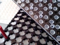
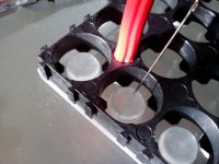
And here are the holders I picked out:
https://www.amazon.com/gp/product/B011HFLFEG

I'm going to try to find the plastic rods, tap, screws, and plexiglass at a hardware store because I have no idea how big I want them to be, but if someone else has used those exact holders and knows for sure, that'd be helpful!

On disassembling my existing packs: I know there is info I haven't found yet on this forum on how to do this, does anybody have links on hand? Assuming I can even separate them from the old packs, I know I have to charge them up, then measure their total capacity and internal resistance. I have the charger, but it'd be nice to be able to measure the capacity of several cells in parallel so I don't have to do this 56 times (I intend to build a 14s4p pack).
 
The Nickel Stips seem pretty good

According to wiki, https://en.wikipedia.org/wiki/Electrical_resistivity_and_conductivity

Resisitivity of Nickel is [6.99×10⁻⁸ Ohms.m]

Lets say you want to uses one 10cm long [0.1m] 100% pure Nickel Strip (not plated steel) that is 0.2 mm thick [0.0002 m] and 8 mm width [0.008m].

The sectional area is 0.0002m x 0.008 m = [0.0000016 m2]

So the resistance of a 10 cm lenght is : [6.99×10⁻⁸ Ohms.m] x [0.1m] / [0.0000016 m2] = 0.0044 Ohms or 4.4 milliOhms

So if you want to pump 50 amps through that 10 cm strip, you'll have a voltage drop of 0.22 V
dV = R x I = 0.0044 Ohms x 50 A = 0.22 Volts

And the power dissipated in heat from the strips resistance will be:
P = dV x I = R x I2 = 0.22 Volts x 50 A = 11 Watts

Most people wont pull out 50 amps thought. And remember, this is just for one strip. Everything also depends on the internal resistance of your cells, and the way you wire them.
Remember basic Laws :

Resistors in series : Rtot (series) = R1 + R2 + R3 + ... + Rn (the total resistance is the sum of all resistances)
Resistors in parallel : [1/Rtot] = [1/R1] + [1/R2] + [1/R3] + ... [1/Rn]

Think of the nickel stips (and cells you use) as resistors that adds up together.

The less total resistance, the less the energy lost to heat (the more the efficient the battery).


For the neoprene foam, I can't personaly say, I have no experience with it. Maybe Snath will be able to comment.
 
Matador said:
P = dP x I = R x I2 = 0.22 Volts x 50 A = 11 Watts

Thanks for the breakdown Matador :). That actually seems really bad to me. Even with my expected 25 amps that's 2.75 watts per strip (I think) and that seems like an unacceptable efficiency loss. I looked around quite a bit for nickel plated copper strips, didn't find any, but since others seem to be doing fine with plain copper strips, I'll try to find those at a hardware store I suppose.
 
You can alway double up on nickel strips. Also cross-linking strips of different cells so that the current doesn't have to travel so far in just one nickel strip but can be shared in different strips might help.
Also remeber that most of the time you might not be pulling the full 25 amps, unless you're pushing it a lot :mrgreen:

If you go for copper, make sure you get the real copper and not copper plated iron or steel.

Aluminium is also a great conductor.... and it's really light !
 
This looks great:

https://www.amazon.com/gp/product/B01F1FN488

Cheaper than what snath uses (I think) and 3x thicker. Would the thickness cause a problem for making the dimples?

Also, here are some plastic rods (a little thicker at 1/4" or 6.35mm

https://www.amazon.com/Plastic-White-Dowel-Tiered-Construction/dp/B00RPMZA0Q

Instead of drilling a bunch of holes and tapping a bunch of rods, what about just securing the case with velcro compression straps?
 
quuxman said:
This looks great:

https://www.amazon.com/gp/product/B01F1FN488

Cheaper than what snath uses (I think) and 3x thicker. Would the thickness cause a problem for making the dimples?

Also, here are some plastic rods (a little thicker at 1/4" or 6.35mm

https://www.amazon.com/Plastic-White-Dowel-Tiered-Construction/dp/B00RPMZA0Q

Instead of drilling a bunch of holes and tapping a bunch of rods, what about just securing the case with velcro compression straps?


It's a simple and elegant design, but it's long term safe function is critically dependent on using exactly the recommended material choices. I love the DIY friendly robust interconnect system in this design, but to function it's imperative the material creep and long term foam compression set% of the materials are right.
 
liveforphysics said:
but to function it's imperative the material creep and long term foam compression set% of the materials are right.

Well speaking of the foam, the one thing I'm not clear about this design is what's actually compressing it against the cells? In snath's picture I see one screw in the center of the case. The plastic rods would compress the cell holders together, but without multiple screws squeezing the acrylic against the foam strips, I can't imagine this would maintain a good connection with all the cells.

As long as there's an even amount of pressure against all the strips, I can't imagine why my material selection wouldn't work out as good or better. Neoprene is used in buildings to distribute load between pieces of concrete. As long as it's closed cell, I think it will hold up fine.
 
Gasses diffuse out of closed cell foams.

You need a material you have defined tested compression set data for or it's inviting fire long term.
 
liveforphysics said:
You need a material you have defined tested compression set data for or it's inviting fire long term.

I've done my research, and I'm confident using neoprene will be safe and effective in the long term, far more so than rubber bands! I'm confident with all the materials I've picked out now, the only remaining questions for me are about which BMS I can use (see my post on picking out a BMS), and wiring the balance plugs. I'd like to go with a series of 6s balance plugs so the far cheaper and smaller 6s balance chargers can be used.

My main question is if I can get away with using the balance plugs in parallel with the BMS, or if I have to do something extra to disconnect the BMS circuitry from the balance wires when the balance ports are being used. I'm also wondering about what connectors to use for the balance plugs. 6 pin JST connectors are a pain to put in and out, and seem like they'd wear out after not much use. However they're so standard I'll probably stick with them, though something like a serial port connector would be much nicer, like snath has done.
 
https://www.robco.com/en/rubber-products

Neoprene actually sucks really badly for this use. ~80% compression set means your pack will lose all but ~20% of your clamp load.

Neoprene is good if you need chemical resistance, but an extremely poor choice over a urethane (or rubber bands even) if you need to maintain clamp loads.

You are an adult and free to burn your bike/house down or whatever you're into that. If you're not into that, it's a lot less stupid to just use the right materials. (Like poron foam).
 
liveforphysics said:
Neoprene actually sucks really badly for this use. ~80% compression set means your pack will lose all but ~20% of your clamp load.

According to this table from stockwell.com it's actually 30% vs the ~3% of Poron foam. I was planning on doubling the thickness from 1/16" to 1/8", so I was thinking there should be plenty of force there, and once it's compressed to the right degree, solid neoprene would do a great job maintaining the pressure. Thing is, now that I look at it again, a 1/16" sheet that's enough for 10+ batteries from mcmaster.com is only a few more dollars than an 1/8" sheet of neoprene, so it's just a matter of convenience of ordering from Amazon, which is negligible. Really, why not use 1/8" of Poron? (86375K233 from mcmaster.com). Even with quite a few screws I can imagine the acrylic could flex enough that the extra thickness could help.

ANYWAY, I'm a lot more interested in questions about the BMS :). Which BMS to use, about wiring that with balancing plugs, and if a 6s balancer can be used on a larger pack in stages if the plugs are wired correctly. Now that I have a nice 6s balance charger, and I see how small it is I'm thinking of setting up my battery so I can actually leave behind the bulk charger on overnight trips. Even if it's unlikely, if the pack gets out of balance on an extended multi-day trip it's much much worse, and would be worth the minor inconvenience of moving a plug a couple times while charging.
 
"...Im a lot more interested in questions about the BMS . Which BMS to use, about wiring that with balancing plugs, and if a 6s balancer can be used on a larger pack in stages if the plugs are wired correctly..."

I think if you start a new thread, you would get more answers from builders who have BMS experience.
 
liveforphysics said:
Neoprene actually sucks really badly for this use

Also, I really appreciate the help from someone with so much more experience with ebike builds!
 
Your best option in making a Snath style pack is copy his BOM lost of materials exactly, and follow his compression height stack-up and crush clearances perfectly.

I typically DIY and tune/hack every design I make, but if I were making this pack I would just exactly copy his design.
 
I will use silicon bumps. :D About BMS, I am searching myself for one that stops and balances to ~4.1V/cell, only exotic stuff there ($$$).
 

Attachments

  • IMG_20160724_173629.resized.jpg
    IMG_20160724_173629.resized.jpg
    47.4 KB · Views: 3,314
  • IMG_20160724_183354.resized.jpg
    IMG_20160724_183354.resized.jpg
    67.6 KB · Views: 3,314
parabellum said:
I will use silicon bumps. :D About BMS, I am searching myself for one that stops and balances to ~4.1V/cell, only exotic stuff there ($$$).
You can check with bmsbattery, they program the high and low voltage for you.
 
parabellum said:
I will use silicon bumps. :D About BMS, I am searching myself for one that stops and balances to ~4.1V/cell, only exotic stuff there ($$$).

Oo, I really like the looks of those bumps. Where exactly did you source them? Wasn't it pretty tedious cutting them all out of the sheet?

On a BMS with a 4.1 HVC, that sounds really nice actually. The bestechpower.com board I'm looking at is adjustable from 4.2 to 4.35, but I exchanged a couple emails with them and they seem very willing to modify their boards. I still haven't gotten a price quote from them, but I already told them I'm initially only buying 2-10 boards for prototyping.
 
Tushar D said:
parabellum said:
I will use silicon bumps. :D About BMS, I am searching myself for one that stops and balances to ~4.1V/cell, only exotic stuff there ($$$).
You can check with bmsbattery, they program the high and low voltage for you.
Yea after I manage to step over my sour experience, I still have 8 custom BMS's that travelled 3 times across the ocean and still cut-off at 4.2V and 2 "smart" BMS's in my junk bin. Have you managed to receive some customized BMS that "worked" at your specification from them?
 
parabellum said:
Tushar D said:
parabellum said:
I will use silicon bumps. :D About BMS, I am searching myself for one that stops and balances to ~4.1V/cell, only exotic stuff there ($$$).
You can check with bmsbattery, they program the high and low voltage for you.
Yea after I manage to step over my sour experience, I still have 8 custom BMS's that travelled 3 times across the ocean and still cut-off at 4.2V and 2 "smart" BMS's in my junk bin. Have you managed to receive some customized BMS that "worked" at your specification from them?
I have no experience with bmsbattery. But they are the only one i know who provide bms with high and low voltage customisation. The price is reasonable.
I am a newbie here. So my knowledge is limited to what I read at ES. Sorry

Sent from my SM-G900H using Tapatalk
 

Attachments

  • IMG_20160831_080549.resized.jpg
    IMG_20160831_080549.resized.jpg
    24.1 KB · Views: 3,274
  • IMG_20160724_174919.resized.jpg
    IMG_20160724_174919.resized.jpg
    51 KB · Views: 3,274
Back
Top