APL's DIY axial-flux motor

APL said:
Might be a few millimeters though, now that I look at it. Should be enough?

Yeah that should work fine. What you want is a bit of air flow, primary goal is to use energy to get the bike moving, not making a gigantic fan ;)
Air has a very low viscosity so it will find its way between any tiny gaps of the coils, I wouldn't worry too much about it.
 
Of course the air need to come out of the motor by the sides. The way you can look at it is that when you make the motor spin, air want to spin with it, when it does, there is nothing counteracting the centrifugal force so it's flying outwards.
The angle of the blades is a hard thing to calculate, i've put them at 45° because lot's of fan i've seen looked like they were at 45. I'm actually trying to learn flow simulation to optimise the radial height of the blades to have sufficient airflow without too much loss and mass (quite a problem with this design). If i can't then i can always shave some mm After testing ^^
Having a small airgap require a bit of negativ pressure to force an airflow, centrifugal fan are quite good at this task.

Envoyé de mon Redmi Note 3 en utilisant Tapatalk

 
Thecoco974 said:
Of course the air need to come out of the motor by the sides.
That's rather difficult to do unless you have something else sucking the air out of the sidecover, externally.

It's much easier to have it go *into* the sides, and come out radially away from the motor, thrown out by centrifugal force like a squirrelcage fan.
 
Sorry I haven't write it right ! When I said the sides it was seeing by the axle, like you said air doesn't want to be forced from thé outside to the inside (radially) it's counter intuitive.
Lebowski actually notice a good airflow with his diy 3 rotor, the interaction between the air and the rotor is actually enough to make it rotate. But as mine his design was going faster than what APL want to achieve

Envoyé de mon Redmi Note 3 en utilisant Tapatalk

 
I think provision for an electric fan might be worth building in from the start. The highest current is at stall and the lowest at peak RPM, the opposite of motor driven air flow so you could end up with little to no cooling when you need it most and a lot of drag when you need it least. It's not that clear-cut of course, there's still high winding and ESC current at high rpm, just low battery current but the lack of cooling under repeated stop-start is an obvious weakness.

I'd been aiming at keeping the bore as large and open as possible, ie. the magnets covering only around 20-40% of the diameter with spokes or large drillings for the rest so there's plenty of area to push lots of air through. That's for a multi row modular arrangement, 6 stator plates and 7 rotors for example before the bore limits cooling capacity. Maybe measure the area between the coils and add them up to see what kind of cross sectional area you'd need to push air through them.

Also, for the core mounting, had you considered cord? Synthetic fibres such as kevlar are crazy strong, about 5x stronger than steel. Always surprises me they're not used more in places where high tensile bolts are essential, things like engine cylinder head and crankshaft bearing bolts. Could simply be the stuff doesn't stretch enough, that thermal expansion of the metal would need sprung tensioners but it could be worth considering if space is really tight.
 
i've thought about the lack of airflow at low speed as well, m'y conclusion on it is that a motor is quite heavy ans as a lot off thermal inertia, si when you design the cooling you need to look at the average speed it's going to turn, of course if you do stop and go at low speed it's not favorable for an integrated fan, but that's most likely not going to be the case, ideally you'd be accelerating and keep an average speed for most of the use Time. I think designing thé cooling for average speed is the way to go, it average the low speed low cooling and high speed high cooling.
For fiber cord it's true they have a very good normal strength, but Steel is used because they're is no simple tensioning possible with cord such as thread for Steel

Envoyé de mon Redmi Note 3 en utilisant Tapatalk

 
That's true. I've been aiming at minimum weight, coreless and enough space to use aluminium instead of copper for the windings so there's been almost nothing to absorb excess heat. Scaling up for use in a trials bike is also one of my main goals so cooling has been a big concern, lots of low speed high torque operation with trials.

One point might be worth mentioning there. I'm pretty much finalised on overlapping windings and getting that to work with a narrow stator (for coreless) results in lots space needed for the inner end turns. That pushes everything out further from the centre, on the negative side it needs a lot of diameter for a relatively small field area but on the positive side it's ideal for cooling, the inner end turns come out almost like cooling fins. Might be something worth looking into if cooling turns out difficult, adding a bit of length to the end turns so they're better exposed to the air flow.
 
Ok now i see why you're looking into external fan cooling :)
Trial is a very specific use case but actually a very good match for an electric swap (loads of low torque needed).
You're talking about aluminium conductor on a coreless build ? That's really interesting ! Have you found a way to limit Eddy current ? Thin isolated aluminium wire existe ? I assume than if it's for trial you're not concern with those since it's not going to turn really fast.
I've been designing my motor with distributed windings too but going the same route as the one featured in a blog discussed earlyer in the thread (ennoid too I think) the winding are angled radially for less end turn losses, but using the overlaping on a straight distributed windings for cooling like you said is actually a great idea since they end up right in the airflow comming from the axials opening ! You could actually shape them in a rad shape maximising air contact surface.
Looking forward to see your results with it !

Envoyé de mon Redmi Note 3 en utilisant Tapatalk

 
I should have known,.. nothing is simple anymore. Theres a lot of science behind centrifugal blade types and uses.

Blade designs.png

Forward, backward, radial, and more. Speeds, pressures and noise levels, I can see why my first attempt at a fan blade
failed, having payed no attention to any of this.

I have a lot to go through here on Images, and theres quite a bit on Youtube as well, but most of it refers to high speed
motors. So not quite the same, but I should have a better chance at getting something to work better.

https://www.google.com/search?hl=en&biw=1680&bih=1012&tbm=isch&sxsrf=ACYBGNSzpy_aq5S-IiwAis2DHXi1BADwzw%3A1572546663258&sa=1&ei=Zyi7XYS3D8y8-gTl8464Dw&q=centrifugal+fan+blade+angle&oq=centrifugal+fan+blade&gs_l=img.1.3.0l4j0i8i30l4j0i24.16706.22918..27612...0.0..0.194.1453.0j11......0....1..gws-wiz-img.......0i67j35i39.MZl5SL-rgVQ#imgrc=_&spf=1572546799878

https://www.google.com/search?hl=en&tbm=isch&sxsrf=ACYBGNSaI1qxHoLgZn_2mDqUsOifo1TVNA%3A1572545590638&source=hp&biw=1680&bih=1012&ei=NiS7XZLBJJ2S0PEP3r20sAk&q=centrifugal+fan+design&oq=centrifugal+fan&gs_l=img.1.1.0l10.26216.34366..38502...0.0..0.159.2113.0j15......0....1..gws-wiz-img.......0i131.pLyldg14w6w#spf=1572545774173

Currently, I'm thinking that it might need to work more like a vacuum, with lower air speed and higher vacuum pressure.
But it's early in the search yet.
 
A lot of information, but not much is relevant to this motors needs, mostly for blowers. It comes down to curved back,
radial, and curved forward blades. Just going to have to play around with it and see what works best for this.

I'm thinking maybe I could 3D print six fan sections out of ABS so they would fit flush and tight and screw on to the 6
spacers. That way I could try out the different types, and always be able to make new ones.
 
In my general limited experience with very low speed squirrel cage fans (usually undervolted DC types I used in computers for audio recording work, for as close to silence as possible), the ones with flat blades angled "backward" or straight out, moved more air than other types. This would be at similar speeds to hubmotors, so it would probably be similar to yours.

At much faster speeds (where the noise becomes considerable, as does the airflow), ones with blades curved "backwards" worked better.
 
Thecoco974 said:
Ok now i see why you're looking into external fan cooling :)
Trial is a very specific use case but actually a very good match for an electric swap (loads of low torque needed).
You're talking about aluminium conductor on a coreless build ? That's really interesting ! Have you found a way to limit Eddy current ? Thin isolated aluminium wire existe ? I assume than if it's for trial you're not concern with those since it's not going to turn really fast.
I've been designing my motor with distributed windings too but going the same route as the one featured in a blog discussed earlyer in the thread (ennoid too I think) the winding are angled radially for less end turn losses, but using the overlaping on a straight distributed windings for cooling like you said is actually a great idea since they end up right in the airflow comming from the axials opening ! You could actually shape them in a rad shape maximising air contact surface.
Looking forward to see your results with it !

Envoyé de mon Redmi Note 3 en utilisant Tapatalk

Enamelled aluminium wire is fairly easy to get, several vendors are stocking it on ebay and most of them are copper coated which should get around the major failing with aluminium wire, the bared ends oxidise causing resistance or failure at the terminal connections. It might even be solderable but I'll not believe that until I see it, soldering aluminium seems like strange voodoo! ;)

Will it work in a motor? I've no idea but I'm expecting problems. The only place I've seen it used is budget welding transformers and considering how competitive the market is for industrial motors I'd have expected it to be used in them too but I've yet to see it. It "should" be as simple as leaving 1.6x the area for windings (alu 1.6x resistance of copper) and Lintz winding should work just as well as copper, there's big savings in both weight and cost so I'm a bit mystified why aluminium never seems to be used :/
 
The main issues with aluminum are higher resistance and difficulty in making good connections at the ends. To get the same magnetic flux, you would need bigger wires if using aluminum. this would make the core bigger, which would offset the weight savings in the wire. I'm sure there is a good reason you don't see motors made with aluminum wire.

Going in the other direction, silver has slightly lower resistance than copper, but is even heavier. We really need that room temperature superconducting stuff or graphene wire.

For the centrifugal blower, the optimum blade configuration depends largely on the back pressure. Forward curved blades will move more air if there is little back pressure while backward curved blades will work better if there is a lot of restriction in the flow path. I would go with the backward curved blades or straight if it makes construction a lot easier.
 
Thinking about it a little, aluminium seems to be not a so bad option for Big axial flux with high winding Space when conductor fill isn't a huge concern. But for coreless i'm not sure it's a good bet since we want the maximum conductor density in the smallest intermagnet space. For cost it means with weaker current capabilities that we need to compensate with stronger magnet or more stack of rotor-stator.
It's an interesting thing to look at though !
I'd still be interested to ear about your findings on it !

Fechter do you have experience with blower design ?
I need to look at APL's links, optimizing the blades of my design is the next step


Envoyé de mon Redmi Note 3 en utilisant Tapatalk

 
I found this link with blower calculators for radial and centrifugal, it also has a lot of general info on all sorts of things
in the left column, and I think calculators for each. But I was disappointed to see a price tag attached.
Still, lots of good free information.

Calculators; http://calqlata.com/productpages/00060-help.html

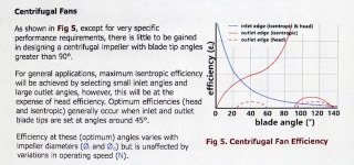
At any rate, they show a graph with blade angles, and mentioned something about 45 degrees being an optimal angle.
I'm probably misunderstanding it, but you probably have it right already. :)

IMG_2069 copy.jpg

Just a thought but, at the RPM's you are going to see, I have to wonder if there might be a 'siren' affect, I think,
as they are constructed much the same? Maybe not.

Fechter, I think In general, they use straight blades because they have a consistent pressure over an RPM range, and are
not prone to gathering dust, but they are also the most noisy. (shop-vac's) I think backwards blades are the most quiet,
and least power hogging. Your right, they are probably the best bet, as there will be a lot of restriction of flow.

As far as aluminum wire goes, I wonder if a copper plated aluminum Litz or multi strand would have more copper content
than single strand? Probably not saving a lot of weight, but any is better.
 
Two advice:
skip the alu wire. Copper cost is not high, why sacrifice performance with poor materials.

Skip the fan. Build an efficient motor instead and you will have no heat to get rid of. Every minute looking at fans is a minute lost designing an efficient motor.
 
IMO axial setups are better off using only one side and not a sandwich type motor, you can find research that suggests this notion, it's because the fringe field where the magnetic flux is concentrated is moved to the outside when using two sets of magnets or coils so you get less torque but the upside is you get less torque ripple.
 
True, there may not be a need for a fan, but cooler copper 'is' more efficient, and since theres room for fan blades
and they can be added without too much effort, then it's a no brainer. It doesn't hurt to learn about fan-tech for future
designs, the general education of present and future readers, and I've got plenty of time to waste. :)

Well I haven't seen any research suggesting that, and I've looked at a lot. I'm not saying that it isn't true, but the greater
percentage of axial's out there are double rotor designs, or single rotor double stator. If there was much of an advantage
to the one sided single rotor design, then all the big companies would be going that way.

Single sided motor designs tend to use a lot of laminated back iron which appears to be a heavier arrangement. I would
prefer to have as little iron as possible, and the lightest motor possible. Thats mostly why I'm going with a separated
'through core' dual rotor motor.
Dual rotor out runners also fit well with bicycle configurations, since they're a lot like a hub motor.
 
Is the motor going to be open to the outside air? You usually only see that with absolute-maximum-power hotrod builds. Here a fan will be beneficial. But if the motor is going to have a sealed shell, there isn't going to be much room for air to move around. A partial oil fill is going to have a much better cooling effect then.
 
APL said:
Well I haven't seen any research suggesting that, and I've looked at a lot. I'm not saying that it isn't true, but the greater
percentage of axial's out there are double rotor designs, or single rotor double stator. If there was much of an advantage
to the one sided single rotor design, then all the big companies would be going that way.

Single sided motor designs tend to use a lot of laminated back iron which appears to be a heavier arrangement. I would
prefer to have as little iron as possible, and the lightest motor possible. Thats mostly why I'm going with a separated
'through core' dual rotor motor.
Dual rotor out runners also fit well with bicycle configurations, since they're a lot like a hub motor.

Take a look at the paper "Design of an Integrated Starter-Alternator for a Series Hybrid Electric Vehicle: A Case Study in Axial Flux Permanent Magnet Machine Design" by Jessica L. Colton. The paper contains some compelling arguments for single sided designs. Regarding the backing iron, if you design using the correct sizing equations there is no reason that a single sided design will have more backing iron.

That said, you will get better power density out of a double rotor design so that is probably the best choice in this instance. I agree with Lars, stick with copper but a few well placed and angled blades could well help with cooling provided you ensure that there is provision for air to enter the motor from the centre otherwise blades are just a waist of time.
 
There are big companies that use one sided axial motors like YASA and others but again if you don't care about power density go with sandwich types. These are easier to get them working since there are no hot spots in the B fields.
 
I probably spoke to soon about single sided weight, sorry. I'll have to take a look at Jesica's papers and provide the link.

I would think that dual rotors have better power density, but nothing can be assumed in motor world, so that needs a
closer look too.

But I know for a fact that cooler copper is more efficient, and is visible if you put power to a coil and watch the flux drop
as the coil heats up. If I could, I'd cool it to absolute zero, but of course I can't. So what I'm saying is any effort to make
the motor run cooler is worth it, whether it needs it or not, so long as it doesn't pull too much power.

I guess it's a personal thing, but I like to have an open motor. It cools better, and I don't ever intend to ride in the rain,
unless I get stuck doing it, and even then theres nothing in these motors (DIY) that can't stand a little water or dirt.
I like to see the insides so that you can see if theres any dirt or corrosion going on, and if there is,.. then take it apart
and clean it.
One of the problems with closed, or supposedly sealed hub motors is that they aren't really. Many of us have experienced
the heartbreak of opening up a hub motor, only to see that it's full of rust, because water got in and we didn't know it.

rusted hub motor..jpg
 
The downside of an open motor is there is a tendency for little magnetic pieces of dirt to stick to the rotor. You'd be surprised at how much magnetic crap is laying on the road. That said, I've run open motors before as have others and it takes quite a while before debris buildup becomes a problem. Rain I wouldn't worry about if you seal all the electrical connections and coat all the surfaces with paint, etc.

If the air intake for the motor is located in a good place it will minimize debris intake.
 
But I know for a fact that cooler copper is more efficient, and is visible if you put power to a coil and watch the flux drop

Huh? Resistance goes up with temperature but is flux of a coil affected?
In what application?
 
larsb said:
But I know for a fact that cooler copper is more efficient, and is visible if you put power to a coil and watch the flux drop

Huh? Resistance goes up with temperature but is flux of a coil affected?
In what application?

This can only happen if the coil has a ferrous core , it can't happen on coreless types.
 
Back
Top