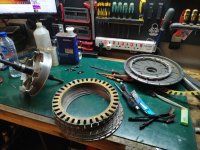
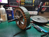
Rewinding a QS 273 motor

Joined
Jan 29, 2016
Messages
961
Location
Shanghai
Hello everyone,

A good friend of mine unfortunately fried his motor recently. It looks like one of the phase partially melted down.
He dropped the motor off to my place yesterday and now I'm trying to see if I can rewire it.
That would be my first time attempting this task, so I thought I'd come here to pick some clever folks brains in order to get as many useful information as possible before trying the rewinding process.

It's a QS 273 rated at 8000W. The goal is to try to make it as powerful as it used to be, or, if possible, even better.
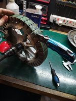
Right now I've started the process of unwinding it, in order to get as many information as I can on its original configuration.
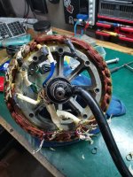
IMG_20230212_200044.jpg

So far it seems like it has 3 turns per tooth, 54 paralleled wires, each of the wires measuring 0.54mm in diameter.
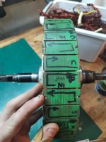
I'm taking notes of the turns orientation and phases numbers by marking them directly on the laminations:
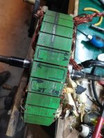
IMG_20230212_221346.jpg

It is quite exhausting to do, the wires are pretty much stuck together. I hope winding will a bit easier than unwinding it (lol I don't think it will).
So far I've successufully removed one and a half phase:
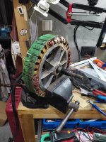
IMG_20230213_001028.jpg

Anyway, it is now time to plan for the rebuild, and since I'm a complete noob I thought I'd ask a few questions before:-

First, wire size:
I have a few options but not sure which one to choose:
-thinner wire? should make winding easier in theory but does it? Could I pack more copper this way? there should be less empty space between winding but more insulation so I'm not sure
-Same wire size? At least I know what to expect this way, but it seems like it's not very easy to work with because it is quite stiff.
-Larger wire size? it will make the winding process a lot harder but then less insulation, less potential failure points, more powah?
-Mixing two wires sizes on the same phase? this way I could have both high infill and high number of paralleled conductors. I've never seen that being done, I had the idea just 10 minutes ago, so I wonder if there is actually a known issue with that. I know that resistances will be different so current will spread unequally, but I assume that since no wire is 100% the same this is also the case even if you use the same wire to make all the windings.

There are also things like skin effect, but they keep saying this only affect windings at "high frequency" without actually defining what high frequency actually is. So does this apply in the case of a hub motor? I'm not sure if the frequencies we're experiencing here are high enough to actually generate skin effect issues, so if anyone has some clear info about that feel free to explain!

Next question would be the wire insulator material. I'd like to get some good stuff, something that can take a lot of abuse. Any suggestion as to what would be a good magnet wire for this application? Also, is there a way to test its properties before so I can make sure I won't discover that it is crap a few days after finishing the project?

Also, I'd like to get some advices from people who have been there already, like Do's and Don'ts.
Like, for instance, it is a good idea to twist the wires a bit before winding? this way thay would stay together during the winding process, but I'm afraid that this would make the phase a little bit longer for no purpose, hence a hgher resistance, plus it would make for a less dense infill.
Is there things to absolutely avoid during winding, like some wires crossing in some bad ways? Are there examples of what is a good vs a bad winding?
Is there a prefered way to start the winding, like is it better to do one phase then the next or should I try to make all the phases at once, coil after coil?
how do I determine how many wires in paralleI can fit for sure? Right now QS managed to fit 54 wires of 0.54mm, but can I fit 55 wires of the same size? I wouldn't want to wind the two first phases only to discover that the last one can't be fitted. Is there a trick ?

One other question: what tools do you guys recommend? I suppose it is quite easy to scratch the insulation with metal ones so I guess wood or plastics is better. Any pictures of the tools you used and their purpose would be greatly appreciated.

Last question for now: do you often scratch the windings while winding? I mean is it something that happens regularly? I which case how do you deal with it? Also, how do you make sure you don't have a short between different turns on the same coil while winding? would suck to finish the whole thing only to discover that one of the coils is shorted to itself. Shorts to the iron core are easy to spot, but shorts within a coil seem a lot more tricky.

I guess that's a lot of questions already but any info you can think of that I haven't mentioned would be really appreciated. Alos links to some good threads would be cool, Ive seen a few but the forum is huge so I guess there are some gems here that I haven't come across.
Thanks a lot in advance for your precious help!
 
The most sure-fire approach is to try to duplicate the original wire size and turns.

You don't need to worry about skin effect at the frequency of the motor.

Look for wire with "Class H" insulation, the highest temp rated stuff.

I've rewound several motors (but smaller ones). You may be able to stuff more copper in the slots, but you may run into issues with the cover rubbing the exposed wire runs. Smaller strands are definitely easier to work with, but won't give the maximum fill because they aren't perfectly lined up to minimize empty space. It's always a trade-off.
 
fechter said:
The most sure-fire approach is to try to duplicate the original wire size and turns.

Indeed, I totally agree with this. But it is also very tempting to try and get more copper in this motor and now is probably the best opportunity to do so...
So I'm not decided yet, still have some time to think.

fechter said:
You don't need to worry about skin effect at the frequency of the motor.

Great news, thanks for the info :thumb:

fechter said:
Look for wire with "Class H" insulation, the highest temp rated stuff.

The max I've seen available so far in China is rated at 220 degree C continuous, I'll probably go with this if possible, it isn't crazy expensive.

fechter said:
I've rewound several motors (but smaller ones). You may be able to stuff more copper in the slots, but you may run into issues with the cover rubbing the exposed wire runs. Smaller strands are definitely easier to work with, but won't give the maximum fill because they aren't perfectly lined up to minimize empty space. It's always a trade-off.

Yes it is always a matter of compromizes. As far as I understand (and please correct me if I'm wrong), in my application the larger the wire the better, but then it makes winding very difficult.
It seems like what matters is the total copper cross section, which right now for this motor seems to be around 0.5mm wire diameter x 54 wires = around 11mm2.
If I were to use just a single 5mm wire diameter I'd get 19mm2, which in theory sounds like it would be possible to fit in the slots with even more room than whatever I have right now. That would be a massive difference in terms of cross section so I believe it is worth considering, not sure how much more power the motor would make because at some point you get into saturation issues, but it would likely run a lot cooler so a lot more reliable.
But then I'd have to deal with a 5 meters strand of heavy copper wire, which would be a total nightmare to bend into shape, if not entirely impossible.

So yeah, cross section vs practicality.... But that leads me to a question, maybe silly but:
Could I just make each coil or at least each group of 3 coils as a separate unit, then join them together by crimping+soldering or rivetting+soldering?

This way I could use very thick wire, yet not having a totally impossible time winding it, only a very difficult one :lol:

At this point any option is still on the table so if any motor guru has a great idea then feel free to propose

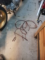
Anyway, meanwhile I got the remaining copper off. I tried to get at least one entire phase out without cutting it. It wasn't entirely possible, had to cut it a few times, but got most of it in one piece. The goal was to get an idea of the total lenght and actual turn count:
IMG_20230213_222014.jpg

So the total lenght is around 5 meters for one phase.
As for the turn count I'm not entirely sure. QS says it is a 58*323, which I believe means 58 wires in parallel and 3 turns on the first coil, 2 turns in reverse on the second coil then 3 turns on the last coil in the same direction as the first one. But I'm not sure how to count the turns, looks like 333 to me. Interestingly, I counted only 54 wires and not 58, so I don't know what happened here. Anyway, I'll do the same turn counts as they did, I don't really want to mess with that, so I noted very carefully, step by step, how the turns were made on my notebook.

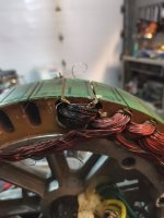
One of the coils was a lot more cooked than the others. No idea as to why, haven't seen anything special that would explain it:
IMG_20230213_202348.jpg

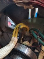
Also, the main phase wires insulation was about to be an issue sooner or later. It seems like QS motors are more and more subject to this problem from what I've heard. I'll replace them with something nicer:
IMG_20230213_220805.jpg

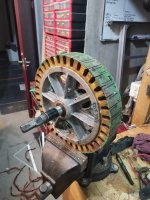
Anyway, now all the copper has been removed. I did damage a little the laminations in some places, and especially this layer of PCB like material, it wasn't possible to do a perfect job, but I'll take care of that before rewinding anyway:
IMG_20230214_000438.jpg
 
I think it would be pretty tough to pull a single 5mm wire through the slots. Probably more like impossible. All the motors I've done I dropped the wires through the slots on the gap side of the stator rather than trying to pull it through from the sides. This means the wire has to be skinny enough to fit through that slot.

I've also had problems with the wire insulation getting damaged by the edges of the slot. That's why there's the thin fiberglass thing and the paper insulators. I used Nomex paper to line the slot hole and protect against damage from the sharp edges.

The phase wires passing through the axle are always tough. Seems like there's never enough room and you need to make some sharp bends. You need insulation that's thin and can take some heat. Teflon is nice but it's very soft and easy to damage. Mostly I see them use nylon. Something like Kapton would be closer to ideal.
 
One more thing to keep in mind; each individual strand has to be stripped before you make connections at the ends. In the factory, I think they use some kind of solvent that dissolves the insulation. When I did it, I had to scrape the insulation off with a blade and then some fine sandpaper. This was very time consuming, but you need to be sure each strand has a good connection. So lots of very fine strands will be a real pain.
 
One more thing to keep in mind; each individual strand has to be stripped before you make connections at the ends. In the factory, I think they use some kind of solvent that dissolves the insulation. When I did it, I had to scrape the insulation off with a blade and then some fine sandpaper. This was very time consuming, but you need to be sure each strand has a good connection. So lots of very fine strands will be a real pain.
I cant' recall who, but someone here used a process with aspirin to remove the insulation.
 
At first we tried it with hot clycerine. But it took much longer than the solder bath.

We have done this 20 years ago for a special made high flexible 70mm² hf cable , in which every very thin strand inside was with varnish insulated to the others because of the skin effect
 
Last edited:
I think it would be pretty tough to pull a single 5mm wire through the slots. Probably more like impossible. All the motors I've done I dropped the wires through the slots on the gap side of the stator rather than trying to pull it through from the sides. This means the wire has to be skinny enough to fit through that slot.
I agree this would be a lot more difficult. But maybe it could worth the effort?
Maybe I could make a few tests: trying to make one coil with different wire thicknesses and types. This way I could see how difficult it is to wind and maybe also compare magnetic strenght?

One more thing to keep in mind; each individual strand has to be stripped before you make connections at the ends. In the factory, I think they use some kind of solvent that dissolves the insulation. When I did it, I had to scrape the insulation off with a blade and then some fine sandpaper. This was very time consuming, but you need to be sure each strand has a good connection. So lots of very fine strands will be a real pain.

Yeah that's right, I kinda assumed that it was an easy task but I bet that's the kind of tedious things that takes forever.
I do have a small solder bath so I can try that. Although... if I manage to fit big copper in there I could probably just burn the insulation off.
That's one more reason to try and fit bigger wire in there I guess, haha
 
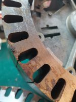
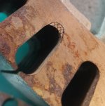
I think I found what caused the motor failure: possibly a rusted core!
What happened is that this motor has been plagued by rust by the past. It then got cleaned and coated, but for some reason the problem reappeared later again.
Rust got between the lamination, which expanded them a lot. Some poles are 4 mm larger than others.
So I guess the coils expanded and it damaged the insulation.


IMG_20230215_223048.jpg
IMG_20230215_223254.jpg
IMG_20230215_223407_1.jpg
It's not a lot of rust but it adds up every layer so that quickly becomes a problem.

So anyway... that changes the plan a little bit.
I could clean all the plates one by one, hoping that the insulation coating is still mostly good, then put everything back together.
Or, I could make a new core.

I'll check the prices, if it's not too expensive that's the way we'll go.
This is currently 0.4mm lamination, but it seems possible to get some good quality ones in 0.2mm, so should I go for it?
Also, while I'm there isn't it an opportunity to try and modify the design very slightly?
I was thinking about making the slot a tad longer, maybe 2-3 mm or less. Enough to make winding a bit easier or to try to fit more copper, nothing too crazy of course, but that could be 10% easily gained. What do you guys think?
IMG_20230215_223254.jpg
 
Last edited:
Expanding the slot might possibly cause the iron to saturate easier.
Indeed, you're absolutely right, but I was thinking the following thing:
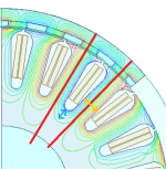
femm hub motor. – Recherche Google - Google Chrome.png
If you look at this image of a motor in finite elements, you can see that most of the flux intensity goes through the core pole (marked in yellow)
But then the bottom part closest to the center (marked in blue) only should see half of the flux.
So my assumption is that it would be ok up to around half of the thickness, so the blue dimension should not be smaller than half of the yellow lenght.

In reality I suppose it's better to keep it a big bigger than 1/2 because flux lines tend to not really like tight bend radiuses.

Right now on my motor both dimensions are pretty much equal, the blue dimension is even a tiny tad larger than the yellow one so I assume there should still be room to play with. Also flu permeability should theoretically increase a little bit with thinner laminations, possibly made of a better material (I'm not sure what it the exact alloy QS uses, but hopefully I can find better stuff).
But at this point I'm just asking questions, any opinion or idea is welcomed
 
Last edited:
I think you’re right about the dimensions. As long as the back iron is at least half the tooth thickness it shouldn’t be a bottleneck.

Thinner laminations will have the same saturation but less eddy current losses.
 
Thinner laminations will have the same saturation but less eddy current losses.
Ah yes thanks mate, indeed you're right. But hopefully some better material might help ? I'm not sure what alloy QS uses actually, but I was assuming it probably wouldn't be the best stuff.

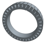
I'm preparing the 3D files of the stator, so far it looks like this, with all the original dimensions I measured:

Untitled.png


Now I was wondering if it would be a terrible idea to reduce just a tiny bit the air gap?
It's difficult to measure the air gap with precision, but I guesstimate it at around 0.5-0.6mm

The stator's outside diameter is 266mm exactly, maybe I can make it 266.1 or 266.2 mm and get a little extra efficiency? Air gap losses increase to the square of the distance so even very little changes can matter here.
The motor wasn't rubbing before so hopefully that should still be fine I guess, but concentricity is always a gamble on QS motors as far as my experience goes, some motors side covers don't fit well.

Last but not least, I measured the magnets at 50mm width, but the lamination stack is only 48mm wide. At least 2mm of laminations could be added easily so I wonder if I should?
Looks like I have room to even fit 4 or 5 mm but I feel like it would be useless to go over the magnet's width, right?

Any thoughts or suggestions are welcome at this stage, I can't modify the core after it's cut!
 
Right, smaller gap is better until it starts rubbing. A few more mm of stator width will help. I don't think if the magnets are wider than the stator it will change things much but you want them at least equal to the stator.
 
Thanks fetcher! I guess I'll do that then.

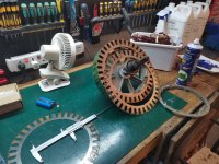
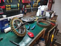
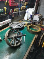
Well, it seems like I underestimated a little bit how difficult it would be to separate the stator core from the aluminum hub. For some reason I thought it would be very easy, but it actually took me 3 hours. No idea why I was assuming that would be easy, didn't really think things through I guess.

Anyway, I used a knife and slowly separated the layers, pushing delicately to remove them with as little damage as possible:
IMG_20230219_231228.jpg
IMG_20230220_003520.jpg

I think that putting a new core back will not be an easy task. The new core should be in one block, I don't think I should install it in several sections.
The best way I could think of would be to use some kind of a press, which I dont have in my workshop. So I'll need to either find a press or to build one. That does complicate things a bit, but a press would be a nice addition to the shop so now might be the right time. An other way could be to build some kind of wooden ring so I can smack the ring all around with a hammer to slowly get the core onto the aluminum hub. Should work fine too but then I take the risk of separating some layers because of the impact's vibrations. So the press is clearly a cleaner/better way.

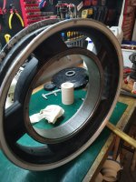
Meanwhile, cleaned the magnets and slightly oiled them to prevent rust. The reason why they look like the surface of the moon is that they got really rusted at some point. The previous owner fixed the issue by opening the motor, cleaning the magnets and using some high temperature paint, which worked well for a few years, but it did not last unfortunately, the rust was starting to get a little bit through the paint again. So I will paint them later using some tough 2K epoxy engine paint, same stuff I use to paint my motorcycle engines, hopefully it will last longer this time:


IMG_20230218_185445.jpg

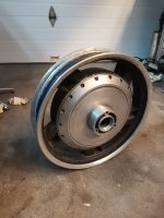
Also worked on the side covers, I plan to repaint them with black wrinkle paint and maybe a bit of laser engraving later.
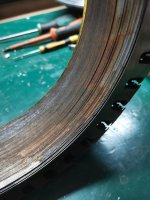
I've also started working on smoothing the rim, it has a lot of damage but it should look almost like new once finished, hopefully.
The rim is also slightly bent on one side, I'll have to correct that.


IMG_20230219_005757.jpg

Ok so I guess the next step will be to order some magnet wires in different diameters and to see how difficult it will be to wind.
 
If you freeze the aluminum stator support core, it will shrink, allowing easier removal of the steel laminations, especially if you can keep the aluminum frozen while you rapidly heat the laminations (with a heatgun, etc) so that they expand outward, loosening them even more.

To install the new lamination stack, preheat it and prefreeze the core, and you might not even need a press to put them together--they may create an interference fit on their own once cooled, if the new stack is correctly cut or machined to the right tolerance to do this vs the core.
Yeah good point, havent thought of it actually. Only thing is I had very little luck trying this approach on other occasions, I tried that on other stuff an failed everytime.:ROFLMAO: But it was much smaller diameter so maybe in this case it will work a bit better.

I'm afraid it would shrink/expand too fast and then get stuck somewhere on the middle. But I'll keep it in mind as it is a lot less work intensive than the other solutions indeed.
Thanks a lot for the input, it helps
 
This whole core installation thing puzzled me for the whole day yesterday. I was a bit afraid installing the new core would be a big hassle.
So I thought it could be a good idea to do a rehearsal, to at least get some experience for the installation of the final core later, to hopefully be able to do it without damaging anything.

So first thing was to remove the last laminations:
IMG_20230220_184833.jpg

As you can see, rust really got everywhere:


IMG_20230220_193155.jpg

So I brushed all of this, got everything as clean as possible with a wire brush:

IMG_20230220_193913.jpg

At this point everything was ready for reassembly.
It took me more than 3 hours to disassemble the core in total. But after removing the rust and getting everything nice and clean, I found out it was A LOT smoother. Reassembling the stator only took me 5 minutes, using a simple rubber mallet with gentle taps so that the core slowly slided back in place.
That was a really good surprise, it is actually perfectly possible to change a motor core with just basic hand tools!

So the core is back together:

IMG_20230220_195938.jpg

Getting the core back together will help making some winding tests with different wire diameters. I'll wind a few coils, check how it goes and decide the final wiring scheme based on that. I've selected a 220 degree C continuous rated copper wire which I hope will do the trick.

Stay tuned!
 
I really enjoy reading the stories that come out of your shop, Dui Ni Shuo De Dui. Thanks for sharing this journey.

Taking a motor apart for a rewind would seem daunting to me, and is something I wouldn’t immediately leap into. And here you are, remanufacturing your motor core with CAD and a utility knife. Well done.

Your tinkering and can-figure-out attitude is inspiring and contagious.
 
Nice. I’ve never done a hub motor rewind.

One thought came to mind; if you deepen the slots, the machine work will tend to create shorts between the laminations. This is bad. The laminations need to be insulated from each other everywhere except where they attach to the center hub.
 
Nice. I’ve never done a hub motor rewind.

One thought came to mind; if you deepen the slots, the machine work will tend to create shorts between the laminations. This is bad. The laminations need to be insulated from each other everywhere except where they attach to the center hub.
Yes indeed you need to pay special attention not to short the laminations together, but I won't machine it so it should be fine: I will ask a specialized supplier that makes stators everyday to build a new one for me. I can't really save the original laminations on this motor because they rusted. I could potentially sand them one by one to remove the rust, then apply some coating on each sheet, but the coating would likely be much thicker than the original thing they used so the core wouldn't assemble properly later.
The laminations need to be insulated indeed, and even at the center hub is better as far as I know the goal is to reach 100% insulation between each layer, if possible (At least that's my understanding of it, I'm clearly no expert so correct me if I'm wrong)

My plan so far is to get the laminations in 0.2mm fully insulated, if possible using epoxy infusion which is a process that should insulate the core, and seal it completely. It should help with eddy currents and also help with protecting the wire during winding.
Right now I'm trying to understand the material side of it, to get the best possible steel I can to make the laminations. There are lots of various alloys, some are more suitable for transformers than for motors, some have better or worse flux permeability, others have more or less core losses.... so I need to choose carefully but it seems rather complicated. Hopefully the supplier will be able to guide me, but better understand a bit what's going on before talking to the supplier.

Also I hope it won't cost too much to get a custom made core, I kinda assumed it would be cheap but I might be in for a bitter disappointment if it turns out it's super expensive!:p
 
I think 230c rated wire is the best available with the common insulation and that’s a rating at 30,000 hours.

Rust on the magnets? I think if the magnet nickel has been compromised and air gets in they will decay to dust

Maybe acid could etch down the laminations so they don’t connect with each other if you’ve sanded them down and would also remove rust

I typically wind with 15 awg wire and tie one end to a doorknob or something and hook the other end on the stator and pull it on and easy. 5mm diameter wire u want to wind?! That sounds very hard but like to see it

I use “heavy build” wire which has double the insulation to avoid scratching through. If the stator isn’t completely free of any exposed steel it could be a disaster and often is for me. Worth checking after winding each tooth or phase. I use layers of kapton tape and especially with pulling on think wire u risk cutting through the insulation, at least cutting through the common green epoxy.

I think the lrk winding is the most fault-proof as none of the different phases’ magnet wire needs to come in contact.

I like wye more and shows better.


I use plastic credit cards and a square edged block of plastic to push windings down to the bottom of the tooth.


If you’re going to do such thick wire maybe rectangular would be best. I forget the link but there’s a place u can get some different shapes in smaller quantities here in usa.
 
Last edited:
Thank you very much for all these very useful answers, it helps a lot!

Rust on the magnets? I think if the magnet nickel has been compromised and air gets in they will decay to dust

Now that worries me a bit: do you think they'll keep disintegrating even after I coat them with epoxy paint? I sure hope not, that's the only thing that seems impossible for me to repair on these motors (essentially because I have no idea where to find replacement magnets and QS doesn't seem to sell rotors separately).

I typically wind with 15 awg wire and tie one end to a doorknob or something and hook the other end on the stator and pull it on and easy. 5mm diameter wire u want to wind?! That sounds very hard but like to see it

Actually 5 mm was more an example to illustrate the most extreme wire that could be fit in these slots, but yeah I agree it isn't practically realistic unless maybe making each coil separately and then joining them together afterward, but even that would be really difficult.
I will however try with 3mm, 2.5mm, 2mm, 1.5 and finally 1 mm. Then hopefully after this test I should have a better idea of what's realistic. At least that's what I'll try. My actual realistic goal is to reach 2mm, that would be 7 wires in parallel for around 22mm2 of section which is double what the motor currently has.

I use “heavy build” wire which has double the insulation to avoid scratching through. If the stator isn’t completely free of any exposed steel it could be a disaster and often is for me. Worth checking after winding each tooth or phase. I use layers of kapton tape and especially with pulling on think wire u risk cutting through the insulation, at least cutting through the common green epoxy.
I'll try and be extra careful with winding, thanks. Maybe some 3d printed tools will make it easier


I think the lrk winding is the most fault-proof as none of the different phases’ magnet wire needs to come in contact.

I like wye more and shows better.

Interesting, but I'll try just copying the same layout as QS did, only mods will be the laminations and the wire sections, I don't have enough knowledge to do more. I'm not even sure what lrk means haha

Also I'd like to see the effect more copper and better core material will have,
But maybe someday on an other motor!


If you’re going to do such thick wire maybe rectangular would be best. I forget the link but there’s a place u can get some different shapes in smaller quantities here in usa.
I've considered it but came to the conclusion that it would be just too difficult. But I'll give it another thought if winding the 3mm wire isn't too difficult... ;)

Do you have some build threads/blog or any other interesting link I could follow? Thanks again!
 
Epoxy coating works for the magnets but is slightly thicker than the original nickel plating. I've seen many epoxy coated magnets.

If the laminations are pressed onto the center hub, it's hard for them to not short to it. But this isn't really an issue since there won't be much flux around the short and therefore not much potential for eddy currents. The insulation is most important where the flux is changing the most.

Not sure what your choices are for lamination steel. You want high saturation flux and low hysteresis. There is usually a trade-off between permeability and saturation flux. I would go for the highest saturation flux.
 
Back
Top