APL's DIY axial-flux motor

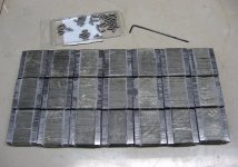
Things continue to get in the way of progress, but we're still moving forward. Should be able to finish the lam stacks
tomorrow, and move on to the bonding process. I found some polyurethane glue that's fairly thin, and it says that it's
good for steel and glass, so we'll give it a try. The lam's are pretty shinny, and I can't scuff them. I'm hoping this glue's a
little softer than resin, which tends to crack. (Titebond Polyurethane, 20 mnts. work time)


Found some nice little clamps at Walmart, for $2. apiece, that should work well for squeezing them lightly. I am hoping for
some glue insulation between each lam. Back in the old days, they actually used paper in between each one, but that won't
work here. I thought about painting them all first,.. but that will turn it into even a bigger project.

Once they're all bonded, I'll mill a channel on each side to reduce the mass, and give the wire a place to go. I want to keep
the core mass about the same as the Crystalyte has for two teeth, or one complete stator magnet.
After that, they will get some primer, and krypton tape, and be ready for winding. :thumb:
It'll be interesting to see what the total weight turn's out to be.

It will also be nice to get back to machining the rotors, and the other motor parts again. :)
 
FWIW, even fi the lams have some shorting between them, it's still way better than a solid bar, as far as eddy currents go (which is the reason to use lamination stacks vs bar).

Keep in mind that many things with lamination stacks have welds across the stacks (to hold them together) that create shorts across teh stacks at those points. I'm sure it affects things a little, but it couldn't be much or they wouldn't do that. ;)

If you ever want to do it, you could hard-anodize the laminations, whcih will electrically insulate them. I don't know how much thickness it will add to them, but the process itself is probably relatively simple and not labor-intensive. :)
 
I'm very impressed with what you are doing
and how well you write it up !!

I've been stuck building an Air gap, Air Core Axial-Flux
Motor/Alternator for many years now
( to lazy to finish winding up the required coils )
{ or even the needed "test" for wire size coils )
For using as a "wind turbine", I'll need to find wire size for low RPM
to get the volts needed for the battery bank being used.
Coils will be around the size of a quarter outside
with a half inch center hole and either 1/8" or 1/4" thick
using the wire I have on hand that I feel will work
Using two in hand when winding.

"using small copper tubing for a wire,.. the idea being that it could be water cooled"
I've been playing with something like that idea also
but only wanted inner most first wrap and then outer most last wrap
with a single or two wraps in the middle.
Coating the tube to keep it from shorting and to maybe keep as separate coil phase from the "cooled" wires ?
But will probably just line the inner and outer of the coils with small plastic/rubber tube
that can handle the temps and have a small radiator above for convection cooling .

BUT,
I do have the mag plates done
Used two industrial sprockets that had bike chain sized teeth
About 6" around and 1/8" thick solid with the right size I wanted for the shaft hubs
5/8" or 3/4" can't remember.
Being that I only had then, 1/2"x1/8" Neo round magnets,[a few over 200]
I had to make them as 5 high stacks going, N,S,N,S,.,., by 20,.,. X 2, using one hundred on each plate
around the outside edge
just below the teeth
luck had it that a blank CD/DVD 50 pack cover was just about right
for the inner wall to keep the resin around the magnets
I wrapped a couple of wraps of braided fishing around the outside
and a layer of "FREE" kevlar cloth then masking tape
Just had to pour the resin in the small mote after that
the clean up wasn't easy as I didn't think ahead as you did and used very little
release agent. But it worked out and these plates even with 4 jacking bolts
are very hard to get back apart when checking the magnet flux strength
down to the less than a half inch, AirGap I'll be having them at when coil plate gets done

Being that it matches Bike chain I keep thinking maybe a Bike motor crank type thing :roll:

Like I said your work is looking very good

Carry on Sir-
 
FWIW, even fi the lams have some shorting between them, it's still way better than a solid bar, as far as eddy currents go (which is the reason to use lamination stacks vs bar).

So true, I was hoping to squeeze more out of them, but it probably won't make that much difference in the end.

I am thinking of trying solid cores in it though, after it's been up and running for a while, as an experiment. Just because it
would be easy to do, and I'd like to see the difference that it makes in a real world test. No respectable company would
ever try to make a motor like that, but as a DIY, I can. It probably hasn't been tried since the 1800's, and I think it would be
interesting to do,..keep in mind that the RPM is only 300 or so, and the three phase frequency is fairly low. As a mid drive,
the current is low as well. It may be surprising, or it may not,.. but I don't think anybody has actually tried it in the last century.

I think all I would need is some low carbon, annealed steel, and I could make solid cores in a day!
 
Thanks johnnyfoos, good to hear about your project,..hope you get it finished. I get a lot of info. from the wind
generator thread's, since they are axial. A little different in the fact that they are mostly air core, but the construction
is pretty much the same.

Thank's for following this build, I'm hoping it will help inspire others,..at the very least, the info displayed here will make
it easier for future builders to tread this path. :)
 
Found this link on lamination bur's, or shorts, for reference. Another 'headache' PDF,..but very good information nun the
less, and should probably be posted here.

Explains all the effects of shorted lam's, with lots of FEM./graphics.

https://orca-mwe.cf.ac.uk/50967/1/06571275.pdf

Just skim through it, to get the jest of it.


I'm still not worried about it, because most of these problems occur with high speed, and high power. :confused:
(Famous last words)
 
APL said:
Found this link on lamination bur's, or shorts, for reference. Another 'headache' PDF,..but very good information nun the
less, and should probably be posted here.

Explains all the effects of shorted lam's, with lots of FEM./graphics.

https://orca-mwe.cf.ac.uk/50967/1/06571275.pdf

Just skim through it, to get the jest of it.

I'm still not worried about it, because most of these problems occur with high speed, and high power. :confused:
(Famous last words)

Cool. I'll get to it as soon as I finish watching all of the "cute kitty" videos I've got lined up. ;^)
 
Good article! :thumb: Check out the photos of the melted (transformer?) core due to a lamination short!
 
Better than watching kitty's,.. and a party pleaser too! :D

https://www.youtube.com/watch?v=J9b0J29OzAU
 
I got a paper with a section on the magnet vs tooth width somewhere on the computer. Let me dig some.. I think it was about wmagnet>=wtooth+tmagnet so that a 40mm tooth would require minimum a 43mm wide magnet if magnet thickness is 3.
 
APL said:
Better than watching kitty's,.. and a party pleaser too! :D

https://www.youtube.com/watch?v=J9b0J29OzAU

I tore myself away from the cute kitten videos long enough to take a look. Pretty nifty. I wonder how hot that battery gets. :^)
 
I wonder what a 3400ma Lipo would do,.. :confused:

Keep a fire extinguisher handy!
 
It's kind of a good lead in for a new motor design I've been thinking about though.

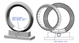
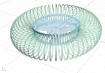
A TFPM, or toroidal flux permanent magnet motor.

I was thinking how all the power and flux of a coil are contained in it's center. Inaccessible, which is why we use iron
cores to move it out to where it can be useful. But as soon as you use iron, you have all the problems associated with it,
reluctance, core loss, eddy currents,weight, heat, etc.


View attachment 2


So the idea is to bend the coil into a circle, and toss the magnets inside, so that they will always be in the most efficient
position possible... the center of the coil. But now you have the problem of connecting an axle to the magnets.

This is not a new idea by any means, there are a few examples, or attempt's, on line, but most are pretty lame, and try
to use the outside, or inside of the toroid, where the power is weak. There is one clever design below that looks pretty
good, other than the mechanical advantage is wrong,.. a big gear moving a small gear.


Toroidal motor.jpg


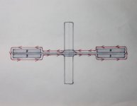
My current idea is to use a partial coil, whith a small gap on the inside, so that a thin disc can be inserted, and connected
to the magnets. There will be some efficiency loss, and wasted wire in the crossover, but it's par for the corse.
The advantage of continuouse inter-coil flux will offset it.

The big advantage is that it can be made mostly out of composite's, the only metal will be the wire, bearings, and magnets.
A person could use a large diameter carbon fiber tube for an axle, and a fiber cog with a belt drive as well.
The disadvantage is the inability fix it once it's built,.. and maybe some cooling issues.


It's three phase, and probably perfect for sinusoidal control, and might not have any cogging if it's wound right. :)
This drawing is just the basic idea, and I didn't draw in all the magnets, or phase coils, which would complicate it.

Whats the verdict? See any red flags?
 
Failure to address reluctance of flux return path around outside of coil.
Not a big deal, just embed in a pipe of laminated iron or bailing wire.
Taking care not to complete an electrical circuit, only magnetic.

Failure to address reluctance of gap for coil to pass through.
Failure to address eddies in copper where alternating flux cuts through.
You could use coils of thin ribbon to reduce eddies, but then the gap is wider...
At best, you propose to bend a loudspeaker into a pretzel?

#1 problem is wire in the gap makes for a big gap.
This is why motors use iron to guide flux to a thin gap.
 
The copper coils have to "cut" the magnetic flux to generate a force. In a toroid the flux stays in the ring and doesn't get out where the copper is.
 
Shot down in mid fight,.. such a pretty bird too. :cry:
Well, I know it has problems, but I think it has merit too.

I don't think it needs any metal around the outside of the coil, the flux path 'is' the coil and magnet. Solenoids don't
use any metal around them, and they work better than anything. Take a look at the youtube video above, the
magnets don't have any trouble moving through the wimpy coil.

Reluctance in the gap is a minor concern, and eddies in copper are unavoidable in any motor.
The amount of area in the gap is only 10 percent (or so) of the rest of the coil, hardly a deal breaker.

And yes, I do propose to make a elongated loud speaker! More like a doughnut though. Mmmmm...doougghhnuutt... :)

Fechter has a good point about the 'cut' of magnetic flux though. Not totally sure if it applies here, but perhaps it should
use steel slugs instead of magnets, (dang laminations again), and then a pulsed square wave to run it. (halls?)
I'm not totally sure that three phase is going to work yet anyway. Something about the magnet orientation.

Another idea is to use a square magnet system, that way it would have the wire cutting across the fields. Hmmm?
Easier to make too.


Square torid.jpg
 
After looking at that last 'rectangle' drawing again, I guess I've come full circle back to an Axial design. Dang it!
Although a little different, in that the coil is 'around' the PM's, which is magnetically stronger, and lighter. I'm not sure
if the PM part of the rotor disc would need to be iron or not.
Sort of core-less, and then again...not. It may even get a kick from the end windings this way.

The new problem is in making the cases, and getting the windings and PM spacing right. Need that 3D printer again..

Another Idea is to use two printed circuit's for the crossover wire's. Although that would require extreme soldering effort,
but would be easier if large gauge wire was used,.. perhaps in a high current model.

'Something' like the picture below,.. imagine the center as two printed circuits of crossover wire, and the outer windings
are cut out in the middle. (And rectangle shaped)


Single turns toridal coil.jpg
 
Well your probably wondering what happened to this AFPM motor build. I'm hung up in the drudgery of bonding the
laminations. I had to use just about every clamp in the shop to hold them just right, so I can only do a few a day.


The polyurethane glue didn't pan out, because it needs to have water sprayed around everything as part of the curing
process, and then it foams up and makes a mess. So I went back to polyester resin, which seems to be working out nicely
I came up with a mix of 20 grams to 5 drops, and it gives plenty of time to work with.

Can't wait to get these things mounted in the motor, so I can move on tho the rotors and back iron.
I've got a pound and a half of wire to wind up some coils, and then I can see how much more I'll need to order for the rest.
 
Inrunner motors.

Pretty sure that the last motor I drew with the crossover coils would lock up, as both sides would want to go
in different directions. Not totally sure though.

Anyway, I thought of a better idea,.. to 'fold' the coils around the outside of the rotor. This way the flux lines are cut,
and going the right direction on both sides. The PM magnets are reinforcing each other, and are sealed inside the case,
making ferro fluid cooling a possible option, to help with cooling a bit.


The coils are on the outside for easy cooling, and winding/rewinding, and theres not a lamination in site! :)

The magnets are still 'wrapped' inside the coils, a lot like the toroidal design, and construction looks a little easier.
Magnets can be quite long,.. these are 50mm on a 9" motor, and could be longer. Motor is nice and thin too.

I messed up the three phase placement on this drawing, but you can get the idea anyway. It's just the basic idea, and
not all of the windings, and magnets are drawn in.

Kind of an 'inside - out' motor. (I.O.) Am I getting warmer?
 
Maybe I don't totally get Faraday, or Topology, but a field
might orient itself through the middle of the coil no matter
how you bent it. What you going to do if this coil's field is
perpendicular to your permanent field? Am I imagining the
picture from too far to see some local effect you are trying
to leverage? Coils on the neck of a TV tube were bent weird
for reasons I don't pretend to understand. Not saying for sure
there couldn't be something to it.

Strike a balance between iron and copper. Too little of one
may require a greater weight of the other to compensate.
May still need iron lams to complete your magnetic circuit
with as little reluctance from free space as possible. Else
you will need unreasonably large current in the coil just to
punch through nothing. Big gaps are great for storing and
releasing high frequency magnetic energy with low flux.
Not so great for dragging heavy things, unless they all but
close the gap in so moving.
 
https://en.wikipedia.org/wiki/Magnetomotive_force

Word I was thinking of earlier but couldn't recall.
Will need unreasonable large current, lots of turns
of tiny wire to push big flux through empty space.

Only because empty space is reluctant to pass flux
that you can do work against it, and store energy
in the nothing. But that stored energy doesn't help
move a motor. you will be fighting two battles at
the same time.

Its kinda weird. A flyback transformer doesn't store
energy in the iron, or the coils, only in the nothing
blocking the easiest flux path. Same for capacitors.
Not in the plates or dielectric (unless piezoelectric),
but electric field stored in the space held apart. For
motors, that space you must store non-mechanical
work in is your enemy.

Only useful when you are trying to keep a flux path from
saturating so you can store even more work in nothing, or
store and release that work faster. Chokes and flybacks...
 
It's pretty much the same as a coreless axial, or wind generator arrangement. Except the coil is not 'one sided'.
It wraps around both sides and squeezes the magnets. Since all the coil wires are radial, they cut across the length
of the magnets, which have the poles facing outward. That's where the 'push' of a motor comes from,.. the radial
length arrangement.
Just another variation on the same old theme

Radial winding stator.


You might be right about back iron, I wouldn't expect this design to have a lot of torque, more of a high speed motor,
or generator. One nice advantage is that the magnets are all the way out on the end of the diameter, for more torque,
or speed, as a generator.

At any rate, I'v decided that I probably shouldn't be diving into concept motors just yet, until I've proven my worth
on this motor that I'm building. I need to earn my "did it" badge first, otherwise everything has been just a lot of 'talk',
so far.

As the old saying goes, "you can draw a design for a magic wand, but unless you have a working model, it's useless".

I do appreciate your opinions, and enjoy hearing your views, they make me think,.. keep em coming!

Once this cold snap is over, I can get back to work on this DIY project. Lamination stacks are all bonded, and waiting to
be cleaned up, and placed in the stator plates, at long last.
 
I got the cores all cleaned up, and everything looks good enough, a few are a little under par from too much clamp
pressure, but will still work. The learning curve takes it's toll on the first try of anything.

One problem is that the lamination material has a very slick surface, so the resin doesn't want to bond all that well,
there always seems to be one lam that gives out and the stack comes apart.

So I decided to wrap the stacks with a few wraps of fiberglass/cloth, to help keep things together, and to provide
the coil wires with some insulation. It will also serve to help lock the stacks in between the stator plates, and
keep things from flying into the magnets, in case one comes loose.

The bad news is that I didn't mill the core sides out, and just left them as straight bars. I didn't feel like pressing
my luck, having come this far. These things are taking up way to much time, and I really want to move on.
Contradict's my "patience is your best tool" rule, but I'm just going to throw it in with the 'tweaks' after the build.

All this means that the cores are a bit hefty, and come out to 4.25 lbs. Probably about a pound over, and not all that
efficient, but like I said,.. plenty of revisions to be made. Tooth shape and size is a never ending affair, and something
to be experimented with along with wire size and wraps.
I measure efficiency by the smile on my face, and the wind in my hair. :)

I weighed the wire it takes for one coil, and it came out to about 40 grams. So take that times 21, and I get 840 g's.
or a little under 2 lbs.
Axle and stator is 3.5, cores are 4.25, and wires are 2, which brings us to around 9.75 lbs. so far.
I have back iron, rotors, and and magnets to go yet. My, my,.. how things add up! :(

I'll have some photos in a day or two.
 
Heres the cores with the first grind, I still need to fine tune them, and give them one wrap of kapton tape,
to insulate them from the aluminum, and help keep them from rusting.


Glass wraped cores.jpg


And finally, a photo of the cores in the stator plate! A bit of fit and finish to do yet, but a milestone nun the less. :thumb:
They will stick out each side about 2mm, so, with the air gap, the induction between the magnets and the aluminum
should be fairly nonexistent.


I'll take some time and wind as many coils as I can, and work on getting everything to fit together properly.
It will be necessary,.. so that I will know exactly where the rotor and magnets are going to be positioned.

I suppose it's time to talk a little about coil wire, strands and turns.
 
Back
Top