Arduino BMS Shield using TI BQ76PL536A (Update 9/16)

Hello All,

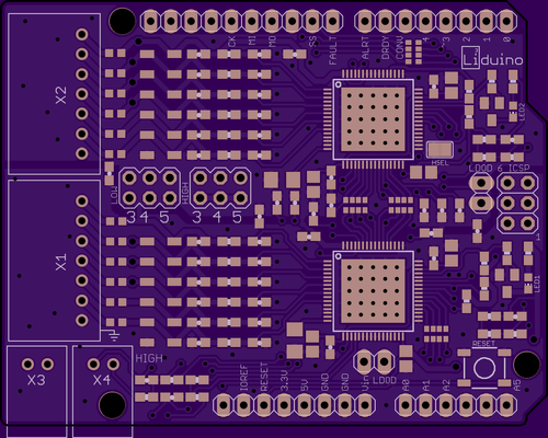
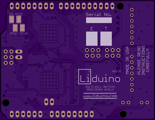
While the idea of LTC based Arduino UNO BMS Shield is fantastic, I am a bit concerned it will detract from other TI specific discussion on this topic and that in truth it really deserves it's own topic so I went ahead and created one: http://endless-sphere.com/forums/viewtopic.php?f=14&t=50639 - please feel free to post anything with regards to the LTC 6804 and variations + LTC Alternatives you may with.

Thank you,
mwkeefer
 
I think.... you should plan an all singing all dancing arduino bike computer to do anything/everything you can think of.... and then get it on kick starter...

I'd be happy to pay for one... and I bet loads of other people here and elsewhere would too...


economies of scale kick in where you can have them made for much cheaper in bulk, and you also have a lot more room to make profit for yourself
(even if you open source it at the end, you'd be able to sell them cheaper than anyone could make them themselves!)
 
knighty said:
I think.... you should plan an all singing all dancing arduino bike computer to do anything/everything you can think of.... and then get it on kick starter...

I'd be happy to pay for one... and I bet loads of other people here and elsewhere would too...


economies of scale kick in where you can have them made for much cheaper in bulk, and you also have a lot more room to make profit for yourself
(even if you open source it at the end, you'd be able to sell them cheaper than anyone could make them themselves!)

While I don't disagree, I know there are a few existing arduino Bike computer projects out there, even here on ES - but again, that would deserve it's own thread and I do believe it would be duplication of work existing :)

-Mike
 
but... there's no bms ? (not that I can find anyway.... a few hints here and there... but no-one sharing any info)


and the bms is the most important bit... the rest is easy with off the shelf parts/sensors/code etc...
 
knighty said:
but... there's no bms ? (not that I can find anyway.... a few hints here and there... but no-one sharing any info)


and the bms is the most important bit... the rest is easy with off the shelf parts/sensors/code etc...

Exactly what do you mean by BMS?

To my perspective there are only a few requirements a piece of electronics MUST meet to be considered a BMS:
hvc protection of proper voltage
lvc protection of proper voltage
balancing

Now that considered there are tons of BMSes out there in commercial and even DIY land but there don't seem to be any decent or appropriate for our LEV use and they are quite expensive and not adaptable or user configurable in very significant ways...

That said, this shield is a BMS which with proper Arduino firmware can and will provide HVC cutout signal, LVC cutout signal and Balancing... there are quite a few more things in granular levels of settings, dual stage LVC (hard and soft signal lines).

In addition these are even now stackable to handle nearly unlimited pack size and were at HW Revision 1.0 with firmware in progress (open source once it's ready for public consumption)...

The only thing you may feel were missing is current limiting and battery cutout and possibly manage PWM to limit charge current at the top end of the charge (balancing point), I could argue that needs to be handled off board so it can be linked remotely to a bank of FETs and a Hall Based Current sensor (+-200A BiDirectional Measurement) and also that with a properly configured charger the current at balance voltage should be low enough that 90ma or so of balance current should be enough... Even the commercially available units I've seen can't handle that rate (they do about 1/2 that).

One step at a time in the DIY Proper world but there are other BMS options :)

-Mike
 
sorry, I meant no Arduino bms, not just bms on it's own

all the other stuff, temperature sensors, speedo, charger pwm, throttle control, data logging etc.. is easily handled with an Arduino and a few off the shelf bits but... I want a bms to tie into the Arduino so I can have everything controlled in one place... and do things like adjust the throttle control depending on the pack voltage/state of charge... but also have it so full throttle always = full power unless the pack is really really flat...

and loads of other stuff like that

I'm not much of a data logging geek..... but with info from the bms, and throttle, and current sensor etc. etc. it would be pretty easy to make up a few graphs and have a better understanding of what's going on... and use it to better program the Arduino :)


also... it'll be good to have a nice bright high quality screen on the bike for speed/voltage/ah info, and there's about a million Arduino compatible screens to choose from off the shelf... might even go with a touch screen :)
 
Knightly,

You are 100% correct there is no decent open source or Arduino based BMS... well technically this Shield is but I do take your meaning about everything but BMS exists based on Arduino / Atmega328 or better processor.

Thanks to the respective specialty work David and I do, he has done a great job of building core hardware for a v1 Shield and I'm working hard at delivering a proper Arduino library for the TI bq chipset to abstract the complexity for the average Arduino user.

All that said, once this is complete (or beta but reliable) then adding sensors, throttle controls / limiters, etc, measurement data, etc (Full datalogger for eBikes and LEVs isn't much further away).

I just find it better to work through one project like this at a time, limit the scope and produce the code in deliverable stages... it helps keeps me on task and moving forward.

-Mike
 
A proper Arduino library is sweet with lots of examples and that clearly explains how to use all the functions :)

I am using a cell log with it as a backup alarm for double testing.

It is not so easy to read voltages in the 1000ths.

I am settling for getting voltages in the 100ths. :)
 
any news/updates guys ?

I've been swamped with work so haven't had any time to do anything....

but some **** pulled a U turn in front of me last week and knocked me off so I've got a bit of time off and time to play!

got a 7inch lcd touch screen too... will mkae an awesome speedo/display.interface for the arduino on the bike

:)
 
I'll let Mike respond regarding the software side. Hardware-wise, I've been working on a current sensing board. Right now it's a LTC2470 16-bit ADC combined with a +/- 50A current sensor in the format of an arduino shield. It can also be used with the Arduino analog inputs, although with much lower resolution. More details will follow once it's built and working.

Boards just came in and I'll be building them up this week.

The project is still active :)
 
Hey guys,

I finally am moved (well that is to say my things are moved, but not unpacked yet) and it's taking me a while to get things up and running, my office / lab / work area is empty since the movers didn't mark the 45 medium boxes which are on a floor below me, let alone the 30+ small boxes and numerous contractor bags.

Short story is, I have my kids this weekend and had to get the living areas ready for them... they go back to their mother either tommorow night or Monday night, then I can begin attempting to setup my office and R&D station areas...

Once I've got my systems up and running and locate the box I packed specifically with these v1 prototype PCBs and the official TI evaluation board I will begin coding again on the BMS firmware, wish I hadn't had to put it on pause but moving took prescidence!

Just like getting ready for bed now does, I have a bday party to take my Daughter to tomorrow too :)

I'll update as time permits!

Regards,
Mike

PS: I'm also / I had worked out a current sensor using a slightly different part with 200A +- range sensing via hall, but it will likely end up the same circuit as David's and we will just offer the various Hall Effect Current Sensors as needed for demand. I have no issue with the 16 bit ADC as I can just oversample it to 12, 14 and yes even 16 bits if needed - don't really think that's needed but I'll let dave weigh in on the situation... the other ASICs or Hall Current Sensors I've seen use SPI so in theory they could share the bus with the TI chips and be addressed by the Atmega, again I'll leave that with David - weve had no time to talk for nearly a week and a half, all my fault :(

(-<)
 
is it not easier to just go with one of the off the shelf current sensors ?

when I looked... there were loads of them around and they were all pretty cheap...


oe are you thinking of building it all into one shield with the bms ?
 
Depends on what you mean by "off the shelf". I'm using the ACS758 sensor, which I consider off the shelf, with the output connected to the input of the LTC2470 as well as routed to the analog inputs of the arduino and optionally connected by bridging a solder pad.

The LTC2470 communicates over SPI, so it can share the bus with the BQ76 ICs and will only use one additional pin from the Arduino. To make it more versatile, the chip select pin can be configured to use any open digital pin.

I'm out of town now but I'll post a schematic later which will make this much much more clear.
 
Definitely something electrical. This does not look good.

rw-batteries-wd-20130714211301985147-620x349.jpg
 
What about joining an Ardulog2to a MAX14921? Both of them support SPI interface, Ardulog already carries an SD card and a logging firmware, and MAX14921 supports up to 16 cells!
That would be a very interesting, cheap and small project!
Unfortunately I have not the tools and the skills to handle SMD devices... so my MAX14921 samples are stuck in a drawer since months!
 
The maxim devices don't seem to support stacking. One of the big reasons I went with the TI chip was that it can be stacked up to 192 cells, which puts it in large scale (car) ev territory as well as small scale stuff like bikes. Other than that, I am including a sd card site for logging and/or storing parameters so it should be similar functionality to what you're suggesting.
 
dmwahl said:
The maxim devices don't seem to support stacking. One of the big reasons I went with the TI chip was that it can be stacked up to 192 cells, which puts it in large scale (car) ev territory as well as small scale stuff like bikes.
They don't call it "stacking", they call it "daisy-chaining" (?).

dmwahl said:
Other than that, I am including a sd card site for logging and/or storing parameters so it should be similar functionality to what you're suggesting.
I know your project is very interesting, I was just suggesting a method to make it more simple (64 weldings are better than 128 :) ).
 
Hey all,

Finally about 50% moved into my new location and up and working, got an emergency pair of contracts this weekend to accomplish (one eBike technical testing and one computer network / point of sale upgrade and overhaul) and then I will finally have a week where I can focus mostly (tuesday to friday afternoon) on setting up a new "formal" work space, trust me when I say everything is everywhere - i more or less work from home now but still have 2 offices and a bike / tech work area to be setup (half setup now).

I'll likely be back in full swing this following weekend and it's a weekend without my midgets so I can actually spend it working on code, household projects, etc.

Just checking in so people don't think I totally disappeared :)

-Mike
 
Hi everyone,

I just want to point out that I am still working on my own board utilizing the BQ76PL536A and this thread is to discuss this board. I am not collaborating on hardware with dmwahl and mwkeefer, because I have a slightly different vision for my board, but we have shared software. I think their board is great and has the benefit of being stackable, but I'm developing mine more for the average ebike user with a 36 or 48 volt pack.

The shield that I made works and is functional, but the first spin of the board left off an important capacitor and improperly routed the CS signal. This is why I wasn't able to provide any boards to those who requested them.

In the next few weeks I will be working on layout for a shield compatible with the Arduino Uno rather than the Arduino Mega, because it's obvious that most people use the Uno. I will make a rev2 of the Mega board when I finish the Uno board.

Hopefully I will have a board ready for beta test with select forum members at the end of this month. I will include several new cool features at were left off the first iteration, and if you have any suggestions, feel free to leave them here and I may be able to include them.

The one thing I am not flexible with is the number of BQ chips per board. The Uno will have 2 chips (supporting up to 12S), but I might be able to squeeze a third chip on the mega board (supporting up to 18S). Also, due to liability concerns, I will not be supporting FET discharge and balancing on the board. The shield will be for gathering voltage data, and will not be used for charging batteries. Sorry!

Some of the features I'm optioning:
- Fused cell inputs to prevent shorting between cells
- LED indicator lights for FAULT and ALERT signals
- You can choose the CS pin used on the board (for example, set it to pin 6, 7, or 8)
- XH input connectors to minimize exposed metal
- Supports between 3 and 6 cells per chip
- Ability to reprogram EEPROM through Arduino
- Ability to leave board plugged into batteries while not in use
 
Just posted an update on the first page. Some of the features that might have to be left off:

- You can choose the CS pin used on the board (for example, set it to pin 6, 7, or 8)
- Ability to leave board plugged into batteries while not in use

I am actively looking for feature suggestions so please let me know!
 
Update for 8/20:

Spent the last week routing the new board, the traces are a lot tighter with the new components and smaller board size. The board is about 90% routed, so I still think this will be possible. I am moving the EPROM programming functions to a separate small board so I can reprogram chips for anyone who doesn't like the default settings. This will lower the BOM cost per board, and component area.

I am trying to gauge interest, and although this thread has a lot of views, it would be helpful to let me know if you're thinking about purchasing a board when they become available. I am looking at the final price to be between $100 and $120 shipped, realistically available about two months from now.

Please let me know if you would like some other features and I will see what is feasible. Thanks for reading!
 
Hey all,

Posted an update on the front page, and reorganized the information in the first post. The PCB should be done pretty soon.

I am trying to gauge interest in the board, so let me know in the comments or via PM if you will want one when they're finished.
 
matterrr,
How's the Aurduino build going? get the boards back yet? I may be interested in purchasing one from you.
 
Back
Top