Arduino cell monitor

dingo117

10 mW
Joined
Feb 8, 2014
Messages
22
Location
Bendigo/Melbourne Australia
Hello people, I would like to share a finished project of mine, and maybe receive some feed back on a few things.

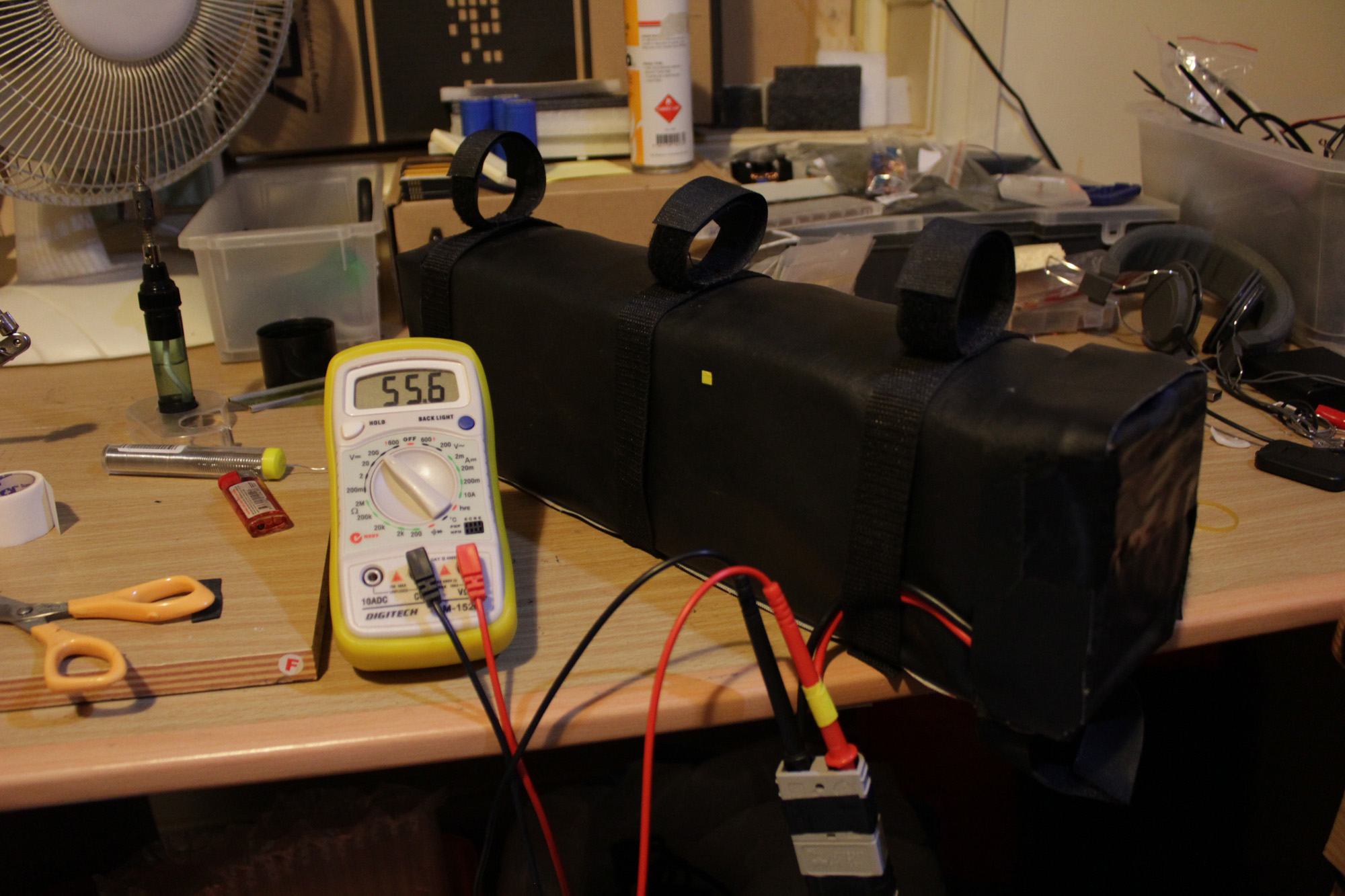
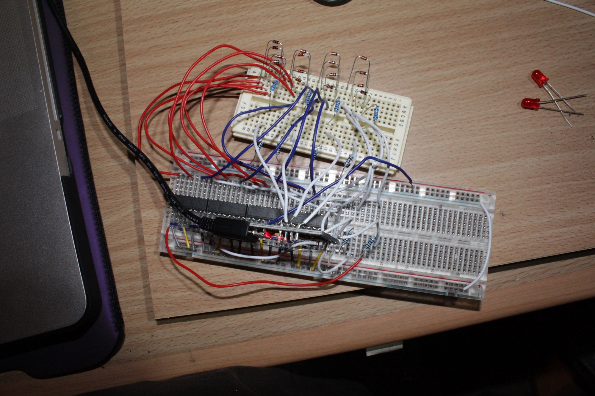
Firstly the project is a simple arduino powered cell voltage monitor for multi-cell battery packs, it just uses 4 analog inputs on an arduino, multiplexes 16 inputs and uses a voltage divider to read the high end of the cells in series voltages. it has 3 trip values high voltage, low voltage and lowest voltage, with various alarm sounds for each one, but later i plan to use the on board memory to store and save the samples for later analysis or use a bigger external eeprom memory.

This system can easily be scaled up to handle more than 16 cells, or scaled down to handle 8, or 12 cells.

The voltage divider steps down roughly a 60 volt input to 5 volts which is safe for the ardunio's 5v analog inputs, the 1024 level input i expect to get (60 / 1024) 0.058 steps in reading accuracy i can expect double this as i have error subtracted from error in the calculations for the final value, but i get around 0.2-0.3 volts inaccuracy any ideas why?

besides this any suggestions for improving or adding on to the functionality of this? maybe adding some cell balancing method to make it a viable BMS? i have thought of that a lot and wondered about doing that with some shunts and serial multiplexers.

All resources are provided for any one wanting to recreate or use this, it is a very simple circuit.
some files are to big/not supported to attach so i have links to them.

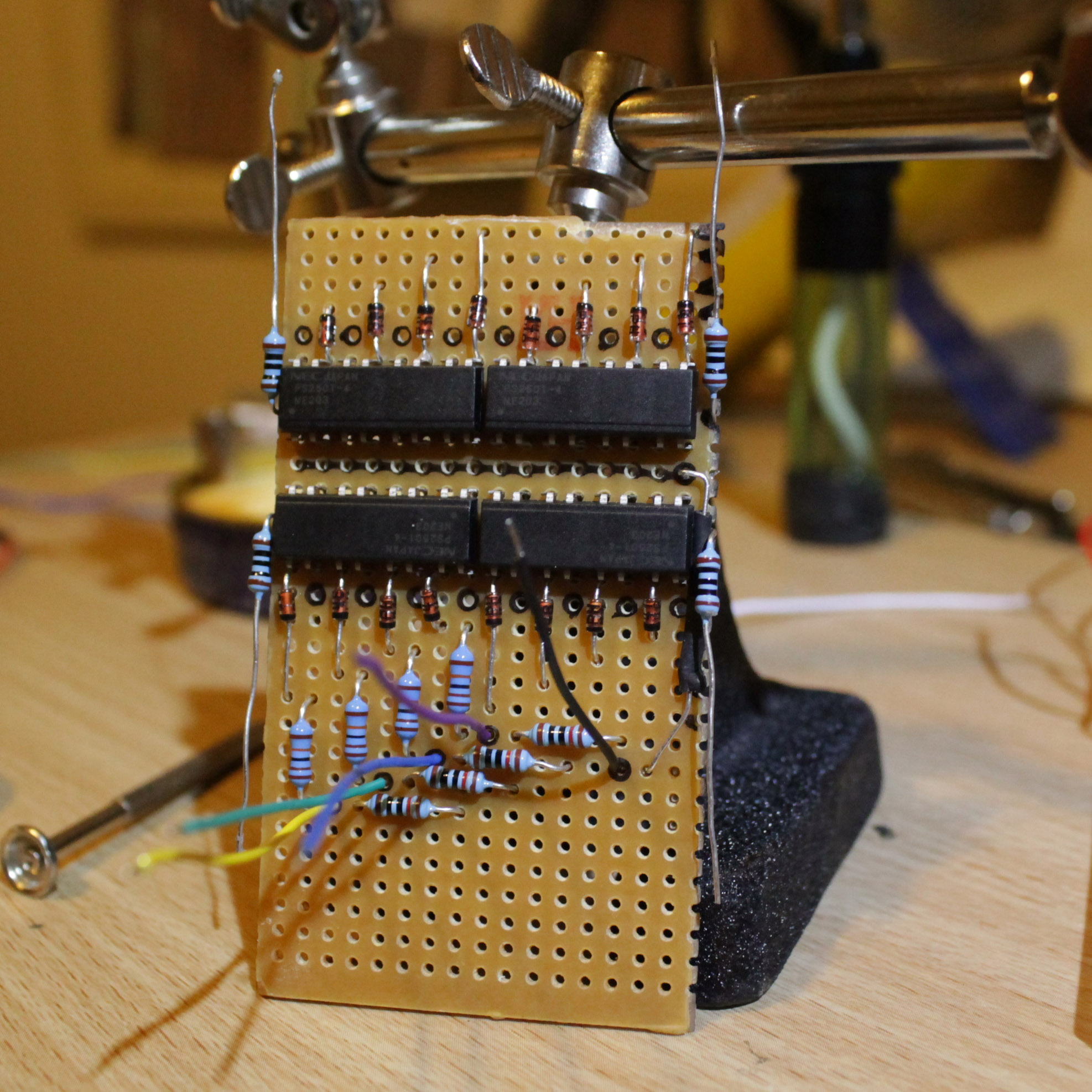
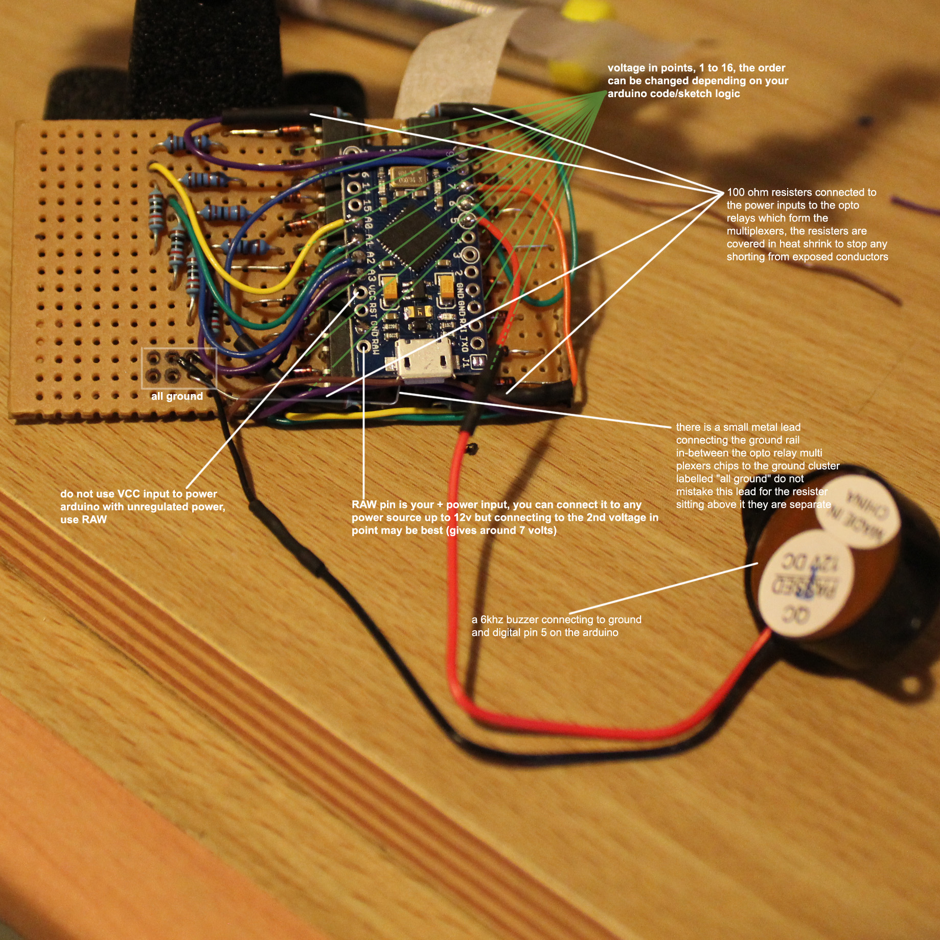
the Arduino board is the Leonardo Pro Micro with ATmega32U4 chip, they cost me like $5 AUD on ebay the rest of the components are super cheap, the optorelays/optocouplers are PS2501-4 Quad optocoupler able to handle 80 volts, to use a higher voltage battery pack find a higher voltage capable component, the diodes are 1n914, signal diodes, the voltage divider resisters are 110k for R1, and 10k for R2.

Edit:
I would highly suggest adding a thermal cutoff / fuse inline of each input, this will lower the chance of a malfunction blowing up your hard work and it will help stop a fire if anything shorts beyond the cutoffs / fuses.
I have also update the code some to be a bit more power efficient and to have an array to use compensation values for each input, also my power saving efforts will effect usb communication for debugging and such as it turns them off, but a little note in code lets you know how to fix that.

cellmon diagram.png
cellmon front diagram.jpg
cellmon front1.jpg

cellmon%20front%20diagram%203.jpg

pack2.jpg

pack4.jpg

pack3.jpg

pack1.jpg

pack1.jpg

testing1.jpg

cellmon%20rear1.jpg

cellmon%20rear%20diagram.jpg

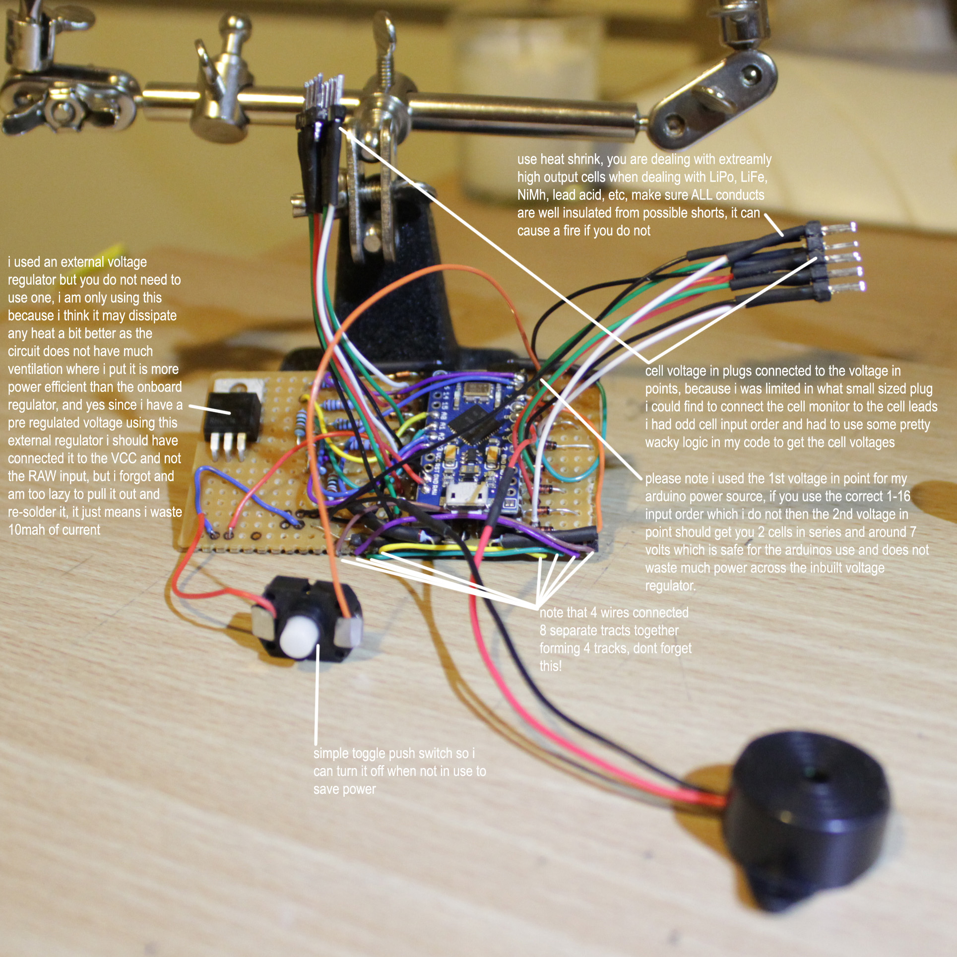
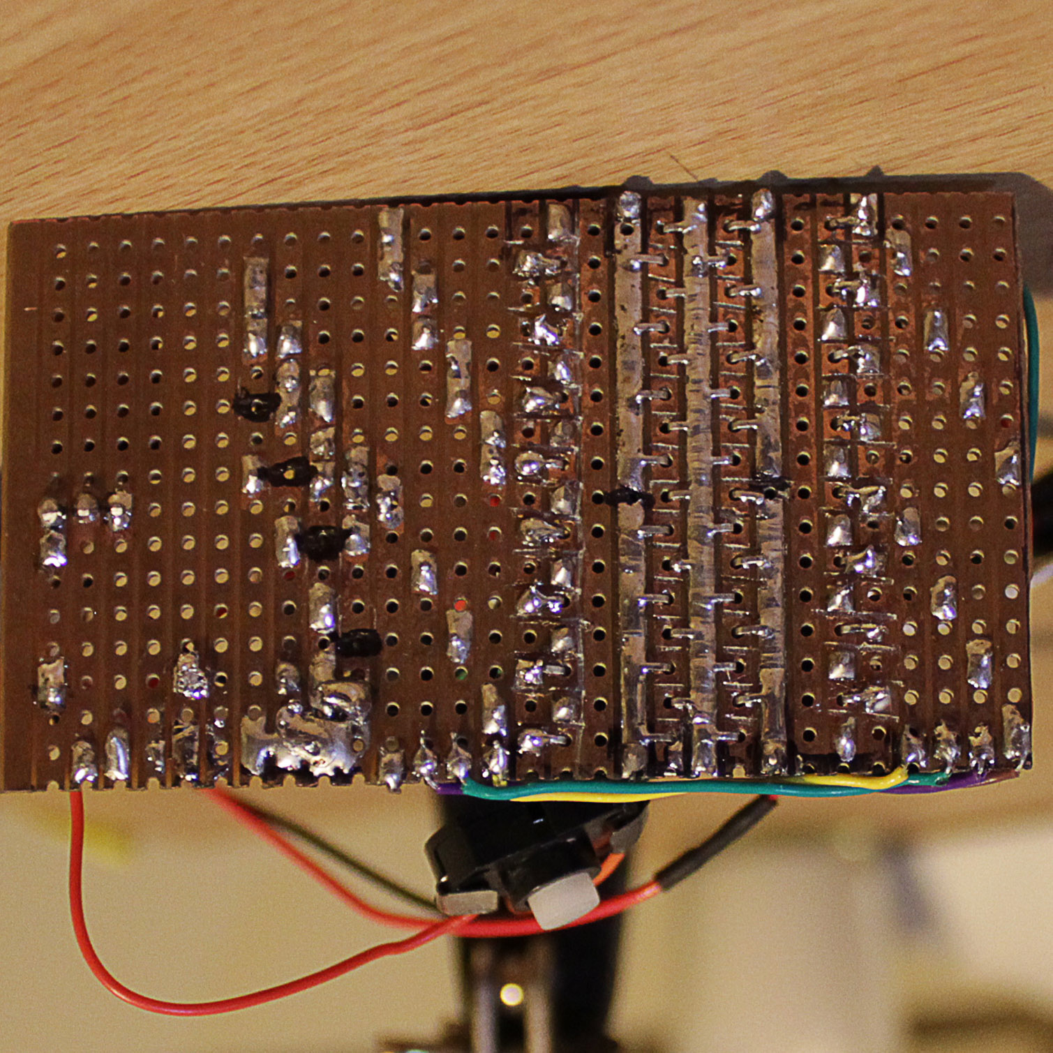
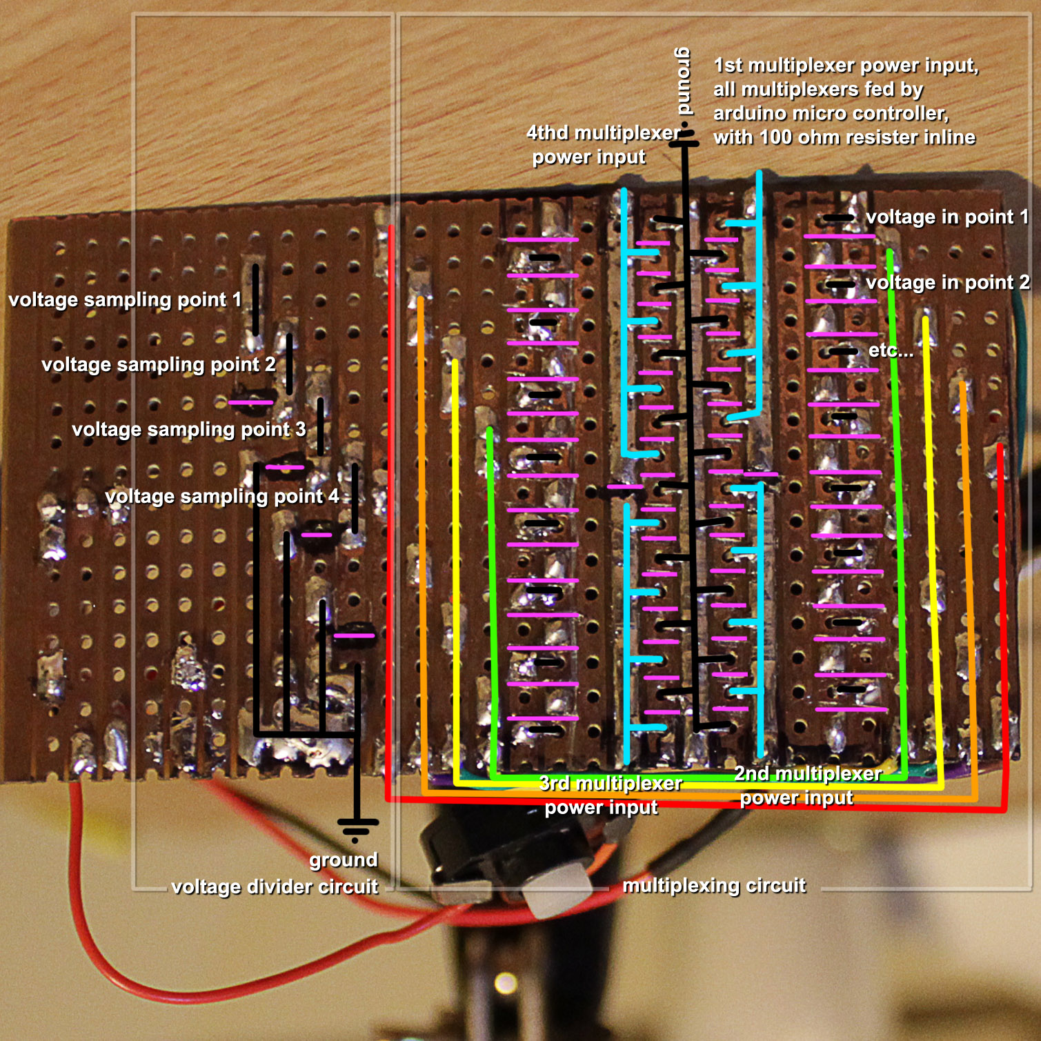
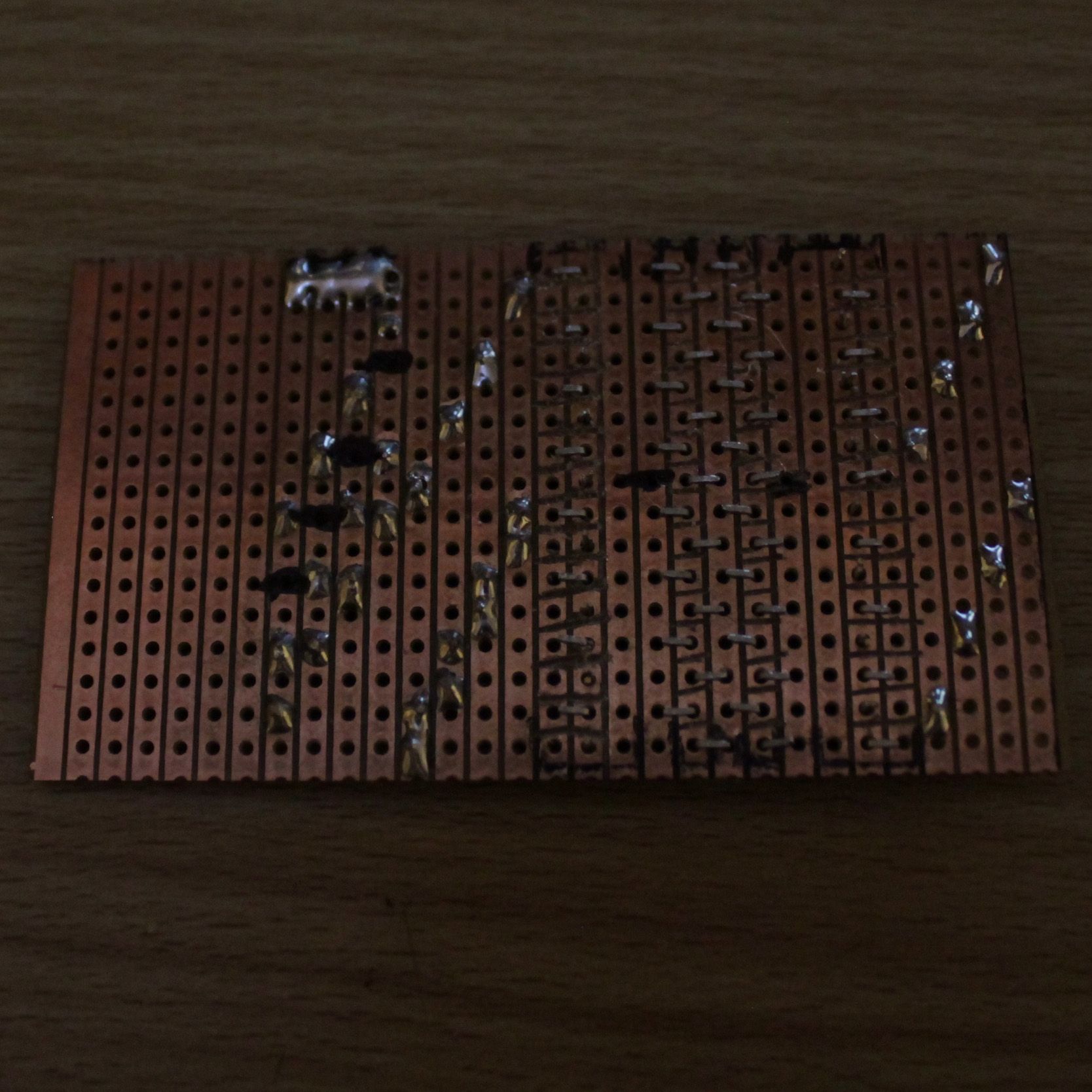
note the PINK lines are where cuts to the track are made they are NOT joints


cellmon%20rear%20cuts.jpg

cellmon%20front%204.jpg

cellmon%20front2.jpg

cellmon%20front%20diagram%202.jpg

testing2.jpg

cellmon%20front%203.jpg

http://amboscience.com/uploads/arduino_cellmon/cellmon_1to16_logic.ino (INO is the arduino sketch /source code file)
http://amboscience.com/uploads/arduino_cellmon/cellmon.fzz (fzz is a file for fritzing, a free circuit design program)
 
The voltage divider steps down roughly a 60 volt input to something between 0v to 1V~3V depending on your resistor value vor the maximum battery voltage you want calculate. So you get not the full 1024 steps.
You have to get a compromis with the VD between not to much wasted power in the resistors and accurate reading. (what are these resistors rated 1/2W 1W 2W?)
The resistors have some variations in there value you would be requed to calibrate all of them to get accuracy.

There are better ways without (VD for every cell) for Arduino to messure cells.
 
zener said:
The voltage divider steps down roughly a 60 volt input to something between 0v to 1V~3V depending on your resistor value vor the maximum battery voltage you want calculate. So you get not the full 1024 steps.
You have to get a compromis with the VD between not to much wasted power in the resistors and accurate reading. (what are these resistors rated 1/2W 1W 2W?)
The resistors have some variations in there value you would be requed to calibrate all of them to get accuracy.

There are better ways without (VD for every cell) for Arduino to messure cells.

i was under the impression that using the equation vout=(r2/(r1+r2))*vin, (10000 / (110000 + 10000)) * 60 = 5 volts, also they are such high value resisters that they only pull around 5 micro amps which is the error of my multi meter i have tested it before using it with the multi meter and the ardino indeed gets very close to 1000 levels out of the highest value cell in series so it is not dividing down to 1-3 volts that i can see. and its only 4 voltage dividers shared amongst the 16 inputs, what methods are better for monitoring the voltages on the arduino also? i am genuinely interested this has been a huge learning experience for me.
 
dingo117 said:
zener said:
The voltage divider steps down roughly a 60 volt input to something between 0v to 1V~3V depending on your resistor value vor the maximum battery voltage you want calculate. So you get not the full 1024 steps.
You have to get a compromis with the VD between not to much wasted power in the resistors and accurate reading. (what are these resistors rated 1/2W 1W 2W?)
The resistors have some variations in there value you would be requed to calibrate all of them to get accuracy.

There are better ways without (VD for every cell) for Arduino to messure cells.

i was under the impression that using the equation vout=(r2/(r1+r2))*vin, (10000 / (110000 + 10000)) * 60 = 5 volts, also they are such high value resisters that they only pull around 5 micro amps which is the error of my multi meter i have tested it before using it with the multi meter and the ardino indeed gets very close to 1000 levels out of the highest value cell in series so it is not dividing down to 1-3 volts that i can see. and its only 4 voltage dividers shared amongst the 16 inputs, what methods are better for monitoring the voltages on the arduino also? i am genuinely interested this has been a huge learning experience for me.

Sorry didn't had read it full there is not on every cell a VD.
Its realy a nice relative cheap & simple design.
I just guessed that its the VD where the inaccuracy comes from.
I self had messured my 80v battery with arduino some time ago and that was what i remembered got only the accuracy for 0-1,5V maybe i had the wrong calculator and information.

When the inaccuracy failure gets found i will build this same for my 20s pack.


There is the accurate option like from dc42
http://forum.arduino.cc/index.php?topic=183588.0

If you can wait some time (like i do) and have a little money for a good accurate voltage monitor.
Liduino shield
http://endless-sphere.com/forums/viewtopic.php?f=14&t=47127&start=75

Or this one but its limitid to some cells i guess.
http://forum.arduino.cc/index.php?topic=156030.0

Search for the LTC6803 complicated stuff but its awesome.
 
zener said:
dingo117 said:
zener said:
The voltage divider steps down roughly a 60 volt input to something between 0v to 1V~3V depending on your resistor value vor the maximum battery voltage you want calculate. So you get not the full 1024 steps.
You have to get a compromis with the VD between not to much wasted power in the resistors and accurate reading. (what are these resistors rated 1/2W 1W 2W?)
The resistors have some variations in there value you would be requed to calibrate all of them to get accuracy.

There are better ways without (VD for every cell) for Arduino to messure cells.

i was under the impression that using the equation vout=(r2/(r1+r2))*vin, (10000 / (110000 + 10000)) * 60 = 5 volts, also they are such high value resisters that they only pull around 5 micro amps which is the error of my multi meter i have tested it before using it with the multi meter and the ardino indeed gets very close to 1000 levels out of the highest value cell in series so it is not dividing down to 1-3 volts that i can see. and its only 4 voltage dividers shared amongst the 16 inputs, what methods are better for monitoring the voltages on the arduino also? i am genuinely interested this has been a huge learning experience for me.

Sorry didn't had read it full there is not on every cell a VD.
Its realy a nice relative cheap & simple design.
I just guessed that its the VD where the inaccuracy comes from.
I self had messured my 80v battery with arduino some time ago and that was what i remembered got only the accuracy for 0-1,5V maybe i had the wrong calculator and information.

When the inaccuracy failure gets found i will build this same for my 20s pack.


There is the accurate option like from dc42
http://forum.arduino.cc/index.php?topic=183588.0

If you can wait some time (like i do) and have a little money for a good accurate voltage monitor.
Liduino shield
http://endless-sphere.com/forums/viewtopic.php?f=14&t=47127&start=75

Or this one but its limitid to some cells i guess.
http://forum.arduino.cc/index.php?topic=156030.0

Search for the LTC6803 complicated stuff but its awesome.

when you reminded me that resisters are never 100% accurate and may need some adjustments i may do some looking in to the inaccuracy of 4x dividers that maybe sending slight inaccuracy cascades across the voltage calculations in the arduino processing and try do some fine tuning which i never bothered to do besides correcting the diode drop.

and i know there are shields and higher accurasy ADC's i can use but if i end up spending enough money why not just buy an expensive digital BMS of some sort ? i wanna learn ! not buy :p
 
dingo117 said:
when you reminded me that resisters are never 100% accurate and may need some adjustments i may do some looking in to the inaccuracy of 4x dividers that maybe sending slight inaccuracy cascades across the voltage calculations in the arduino processing and try do some fine tuning which i never bothered to do besides correcting the diode drop.

and i know there are shields and higher accurasy ADC's i can use but if i end up spending enough money why not just buy an expensive digital BMS of some sort ? i wanna learn ! not buy :p

Now i know maybe the failure.
Its the AREF you need a external 5.000?v high precision voltage reference. And calibrate the 4 x VD resistorfactor. :mrgreen:
Read here http://www.re-innovation.co.uk/web1...nics-information/accurate-voltage-measurement
 
I like the hi-res. pictures. Just right-click and than 'safe as' on desctop.
 
whatever one prefers :) i don't like it, as it's a hassle to read the thread. of course having more detail is always nice. i would prefer if the board would scale the pictures down so you can have an overview and a single click opens full res picture - like some others do it.
but back to topic: i guess as it's and arduino you can attach some kind of display? is this planned? or is it sound only? i had some lipo alarms attached to my batteries but never heard them when wind noise was high.
 
izeman said:
whatever one prefers :) i don't like it, as it's a hassle to read the thread. of course having more detail is always nice. i would prefer if the board would scale the pictures down so you can have an overview and a single click opens full res picture - like some others do it.
but back to topic: i guess as it's and arduino you can attach some kind of display? is this planned? or is it sound only? i had some lipo alarms attached to my batteries but never heard them when wind noise was high.

it is just sound for now, a 90db buzzer should get any ones attention and if its to quiet inside a case may want to mount it outside or put small holes in the case next to it so the sound can escape. i am sure if some one was to get a serial alphanumeric display they could easily display the voltages on a screen, just need the right library or to make your own for the display, arduino has a huge support basis for things like this. my main concern was to make a simple system to make sure the battery never runs one cell to low and ends up ruining it like what has happened to me before as some battery management systems don't cut off power based on individual cell voltage but overall series voltage. my main concern is still trying to get the voltages with in what should be the error range of the arduinos ADC
 
zener said:
dingo117 said:
when you reminded me that resisters are never 100% accurate and may need some adjustments i may do some looking in to the inaccuracy of 4x dividers that maybe sending slight inaccuracy cascades across the voltage calculations in the arduino processing and try do some fine tuning which i never bothered to do besides correcting the diode drop.

and i know there are shields and higher accurasy ADC's i can use but if i end up spending enough money why not just buy an expensive digital BMS of some sort ? i wanna learn ! not buy :p

Now i know maybe the failure.
Its the AREF you need a external 5.000?v high precision voltage reference. And calibrate the 4 x VD resistorfactor. :mrgreen:
Read here http://www.re-innovation.co.uk/web1...nics-information/accurate-voltage-measurement

i will take a closer look at the 5 volt output of my voltage regulator and make sure its as close to 5.00 as possible but i am sure 5% tolerance resisters may be at fault here, if in code compensation doesn't work i may try 0.1% tolerance resisters
 
dingo117 said:
The voltage divider steps down roughly a 60 volt input to 5 volts which is safe for the ardunio's 5v analog inputs, the 1024 level input i expect to get (60 / 1024) 0.058 steps in reading accuracy i can expect double this as i have error subtracted from error in the calculations for the final value, but i get around 0.2-0.3 volts inaccuracy any ideas why?

besides this any suggestions for improving or adding on to the functionality of this? maybe adding some cell balancing method to make it a viable BMS? i have thought of that a lot and wondered about doing that with some shunts and serial multiplexers.

Firstly congratulations on actually taking your concept through to a working prototype. Looking at your code it appears that you are adjusting for the forward voltage drop of the diodes but not the saturation voltage for the CE junction of the transistor in the opto isolator. I suggest that you accurately measure the voltage drop across each diode and opto for each cell and put that correction value into an array to be accessed at calculation time. Regarding the voltage divider network you should accurately measure the values of each resistor in the network and use the measured values in your calculations rather than face values. Equally with the Vref you need to measure the actual voltage and use that. Providing your power supply is stable you can compensate in your software for the different Vref in the same way as you can for the resistor values. At the end of the day with the Arduino's 10bit A/D converter measuring a 12S pack worst case would show about 131mV error. Moving to a 12 or 16 bit external A/D will improve matters as would differential amps on cells 2 and above but it all rather defeats the purpose of using the onboard facilities of the Arduino.
 
The resistor-divider can be calibrated in the software.
Have a look at my Arduino based 7s BMS:

http://endless-sphere.com/forums/viewtopic.php?f=14&t=44100
 
dingo117 said:
i will take a closer look at the 5 volt output of my voltage regulator and make sure its as close to 5.00 as possible but i am sure 5% tolerance resisters may be at fault here, if in code compensation doesn't work i may try 0.1% tolerance resisters
Any luck with calibration?
Some sources say that the arduino have 4.995V not 5.0V.
 
zener said:
dingo117 said:
i will take a closer look at the 5 volt output of my voltage regulator and make sure its as close to 5.00 as possible but i am sure 5% tolerance resisters may be at fault here, if in code compensation doesn't work i may try 0.1% tolerance resisters
Any luck with calibration?
Some sources say that the arduino have 4.995V not 5.0V.

the voltage input can be compensated for, adjusting for each input does improve the accuracy to about the 0.1 mark as i expected, i should update the code i guess! will re-upload i, it will show 1.1 in the version once i am done
 
I've been told that voltage divider is not a good solution for cell monitoring due to low precision.
A multiplexer-based solution would be interesting, but I can't figure out which multiplexer (or multiplexerS?) I'd need to check a 20S/64V LiFePO4 battery without frying anything... Any suggestion?
How can I electronically simulate the use of two terminals of a multimer to check cells individually?
 
jumpjack said:
I've been told that voltage divider is not a good solution for cell monitoring due to low precision.
A multiplexer-based solution would be interesting, but I can't figure out which multiplexer (or multiplexerS?) I'd need to check a 20S/64V LiFePO4 battery without frying anything... Any suggestion?
How can I electronically simulate the use of two terminals of a multimer to check cells individually?

I think it would be up to the ADC precision that limits a voltage divider. Also a multiplexer is just a system that gives multiple inputs a slice of time to access a single channel, the one i made is just hand made it just uses optocouplers/optorelays to switch between the many inputs to the fewer inputs and the arduino triggers the right one at the right time, you can scale up this type of system to as many digital outputs that are available on the arduino which is 19 i think for the pro micro so you could swap 19 inputs between one single output with this. but as for commercial serial controlled multiplexers that can handle way more inputs you will have to do some hunting! and i doubt they will be able to handle 72 volts which is what 20 LiFePo cells in series will give you.

Additionally a standard multimeter needs a short amount of time to sample and average a voltage i think, maybe half a second, so you will need a multiplexer that gives you good control over the sharing time of each input, the "slice" of the pie.
 
Some time ago I ordered free samples of Maxim MAX14921... but they're still in my drawer as I am not able to solder them! :( It would be great to be able to have an arduino shield making use of this device or similar one, I found quite a lot of them:
http://jumpjack.wordpress.com/2012/08/20/componenti-per-monitoraggio-batterie-al-litio/


http://endless-sphere.com/forums/viewtopic.php?f=14&t=50639&p=749526
 
I guess my ideal cell monitor would have minimal power leeching on any particular cell so all drain is even or just very low. The other thing I would like to see is blutooth ability to andriod or ios for an app to show a cell is low at minimum, ideally seeing voltage of all cells would be great.
 
I'm using 1% resistors in my divider, 4uA drain, 35mV resolution on the top cell.
By taking multiple samples and averaging final resolution is better.
 
circuitsmith said:
I'm using 1% resistors in my divider, 4uA drain, 35mV resolution on the top cell.
By taking multiple samples and averaging final resolution is better.
35 mV resolution is not good if you consider that 50 mV means "unbalanced cells", given that 300 mV is the difference between a depleted and a full battery.
 
Couple of comments for you as I've already designed a number of "arduino" cell monitor/balance boards, both professionally and as a hobby. A couple based on the BQ76PL536A from Texas Instruments, and another one based on a single ATtiny attached to each battery cell. In all cases I was very careful about tolerance stack-up and was able to achieve better than 10mV accuracy. In the case of the TI chip It was only a few mV of inaccuracy.

Your accuracy will be limited by many things...
1. Tolerance of the resistors will be a big one. Even 0.1% resistors will add up, since any error in one will shift the adjacent cell value, and these will compound. You could calibrate the readings by measuring the actual value of each component and compensating for it in your calculations, but that will be time consuming and would need to be done for each one, not to mention being limited by the accuracy of your measuring device.
2. Input impedance of the microcontroller's ADC is in the 10k range as I recall (or something close to that). If you have a very high input impedance such as with an array of high value resistors, you should put a small bypass cap across each node to lower the impedance, 0.1uF should be plenty. (Remember that impedance and resistance are not the same thing). From your 4uA comment, I'm guessing you're using 1M resistors.
3. If I read your schematic correctly, you're measuring the cell voltage through an optocoupler and a diode, both of which will have imprecise voltage drops. Not only will the voltage drop across each device vary from part to part, it will also vary depending on ambient temperature.
4. Using the Arduino's supply voltage as the ADC reference will also be a possible source of error. Depending on how stable the 3.3V supply that you're using is, ripple can cause inaccuracy in measurements
5. The microcontroller ADC itself has a certain amount of inherent inaccuracy and non-linearity

I may have missed a few items, but you get the idea. A digital BMS is not a simple thing, regardless of how you do it. If you really don't want to use one of the cell management ICs (I've used the BQ76PL536A in several projects), look into level shifting with op-amps. It will be much more accurate and not require so many opto-couplers, diodes, etc and all the associated error. Otherwise take a look at the projects listed in my signature, you might get some ideas there.
 
dmwahl said:
1. Tolerance of the resistors will be a big one. Even 0.1% resistors will add up, since any error in one will shift the adjacent cell value, and these will compound. You could calibrate the readings by measuring the actual value of each component and compensating for it in your calculations, but that will be time consuming and would need to be done for each one, not to mention being limited by the accuracy of your measuring device.
2. Input impedance of the microcontroller's ADC is in the 10k range as I recall (or something close to that). If you have a very high input impedance such as with an array of high value resistors, you should put a small bypass cap across each node to lower the impedance, 0.1uF should be plenty. (Remember that impedance and resistance are not the same thing). From your 4uA comment, I'm guessing you're using 1M resistors.
3. If I read your schematic correctly, you're measuring the cell voltage through an optocoupler and a diode, both of which will have imprecise voltage drops. Not only will the voltage drop across each device vary from part to part, it will also vary depending on ambient temperature.

In my setup the Arduino code has a calibration table to correct for resistor tolerances. I measure the actual cell voltages with a DVM. Then adjust the table #'s so a printout from the Arduino matches the DVM readings. I'm actually getting better than 35mV accuracy by averaging multiple readings.

I have CMOS op-amps between the resistor dividers and the Arduino.

The opto-couplers are for driving the PWM balancing shunts across each cell.
 
Back
Top