Axial Lifter?

APL

100 kW
Joined
Aug 6, 2018
Messages
1,113
Fun, fun, fun.

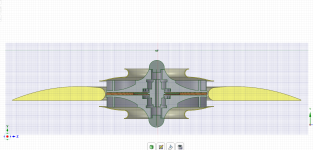
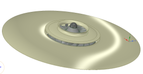
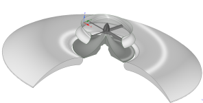
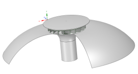
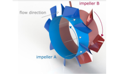
I've been thinking about a ducted circular wing lifter for years, but recently the idea of a counter-rotating coreless axial prompted me to draw one up. Seems to fit together nicely, has balance and symmetry, but,.. does this thing have a chance in hell of getting off the ground?

I know I'm missing like the first law of reality or something, and don't know too much about air speed, wing shape, and lift, so help
me out here. Shoot it down and I'll move on. (lock and load!)

Concept drawing, so no bearings or magnets, and dimensions and details are vague. :wink:
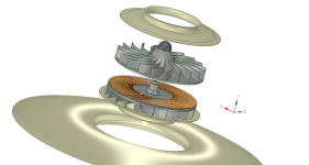
Counter rotating impelers.png

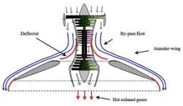
Wing cross section.png

Axial lifter.png
 
APL,

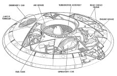
The Canadians tried something similar, called the Avrocar, back in the 1950s. It was supposed to be VTOL, and (gasp) supersonic. It never got ten feet (3 m) off the ground, and it was very slow. They basically invented the hovercraft. Aircraft and rotating masses are not a friendly mix, due to gyroscopic forces. Get a bicycle wheel, suspend it on a string by one end of the axle, and let it hang horizontally (as would your gadget in the air). Spin the wheel, and apply force to tilt the rotating wheel in any direction. Gyroscopic forces will cause the wheel to respond at right angles to any force applied, such as trying to create a bank angle, climb, or dive. Confused yet? Try it. With counter-rotating masses, the gyroscopic forces would equalize, but changing pitch or bank angles would be difficult. Control would be limited, and slow to respond.

The USAF once tried spinning up the wheels of a large plane in mid-air, so the tires would not wear so rapidly (the tire "chirp" you still hear at any aircraft landing). The spinning tires made control of the flying aircraft into a real problem in any banked turn, and as the aircraft changed heading to either side in that banked turn.

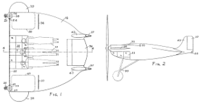
Now there once was a "round" aircraft that was to be the replacement for the F-4U Corsair of WW-II. It was the F-5U (Vought V-173), nicknamed the '"Zimmer Skimmer" because Charles Zimmerman was the inventor, and it looked like the flat hat ("skimmer") of the country-club sporty-car set back then. It was the only aircraft I know that had a clutch and transmission. You launched in low gear, and shifted to high gear for normal flight. It was a STOL aircraft, like the German Fieseler Storch, before many people even knew what that was; it took off and landed at a very low speed, on very short runways. It was intended for aircraft carriers. The pilot flew prone, like a hang glider pilot, able to look down, up, and to each side easily. Jets made it obsolete, but it worked as designed. I have always thought it would be a great sport-plane design, with the counter-rotating props, but the machinery needed was just too heavy and expensive. As long as you made the RPM equal on each prop with electronics, an electric version of the Skimmer would be far better than the original. I could even see it as a hybrid, with a small central gas engine turning a generator to power the prop motors (the aircraft equivalent of a Diesel locomotive, having no transmission or driveshafts). The light weight and instant torque of electric motors today would make it practical.

Your idea would be difficult to control, with the reality of the large gyroscopic forces involved. Sorry I don't have better news.
 
Thanks for the awesome info red :thumb: , I expected to see this craft in a heap of rubble this morning, but so far it just has some good size bullet holes in it. :)

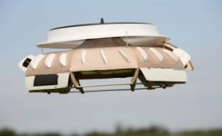
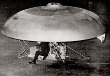
I've seen the Avrocar and Vought V-173, but the Avrocar is apparently a vertical thrust fan with some side ducting, (might be wrong about that), and the V-173 seems more of an airplane with a round wing.

Avrocar.jpg

Vought V-173.png

If I can get past the first part, "can it work?", then the perceived use for my hypothetical lifter is as a crane and not a plane. In that scenario the centrifugal effects add to the stability, as do the limited horizontal movement. A very stable platform with lots of wing surface.

As a crane, it could be tethered, and power delivered to it. Possible uses might be lifting over water & rough terrain or search and rescue in inaccessible areas. But then I'm getting WAY ahead of myself,.. and it's not really the inventors job to figure out a use.

I guess the real question I have is "can a wing shape provide lift without forward movement"? I've seen birds seemingly lift off the ground in the wind by skillfully adjusting the angle of attack, or gulls hovering in place, and who can forget the tethered airplane floating in the movie Flight of the Phoenix? (OK, that's just a movie)

On the other hand, I get the feeling that this craft could be like trying to lift yourself off the ground by pulling on your bootstraps.
 
The lift on a wing is generated by moving air along it's surfaces in a specific way within a specific speed range (specific to the wing shape in question, and air conditions present, AFAICR), regardless of how that air movement is generated.

For instance, a helicopter moves the wings in a circle, instead of the way a fixed-wing craft moves them forward.

In your case you're moving air from the inner circumference to the outer one, IIUC--if the air moves in the right way and fast enough to create enough lift, it does the same job.
 
APL,

If you intend for the circular disk to work as a wing, and make lift to carry the vehicle, you would want both of the impellers above the disk, throwing air across the upper surface only. An airfoil shape to that circular disk (as seen in cross-section on either side of the impellers) may be unnecessary, and may even be detrimental. There is no need for airflow under the disk to have a lifting force above it.

Cut a strip from a light plastic bag, half as wide as your mouth, and maybe 10" (25 cm) long. Hold the corners of one end of the strip so the end of the strip is just across your lower lip, and blow a stream of air out horizontally. The strip will rise to the bottom of your air stream, with no airflow und the strip. This is the "lift" you get from air moving above an on object, with no air moving under (below) the object. Your invention should rise like a cork in water. You can test this result with a model using no moving parts, just compressed air from a very light hose, spraying air out horizontally in all directions above the disk. The bottom of this 360 degree stream of air should be just touching the top of the lifting disk.

You would not want the bottom impeller inhaling air from below the disk. Your top impeller would need to have a hollow core, to allow the bottom impeller to get air. Life just got a bit more complicated, there.

You may find that the the lifting disk works better if the outer edges curve downward to some degree, so the air leaving the disk is curving downward as it leaves. Not sure if that will be much help, or maybe a little, but it's a time to tinker.
Have fun!
 
Awesome news guys, looks like the wing-thing is still flying. (theoretically)

Amberwolf, you talked about airspeed, and I've been struggling with thought experiments on what that might be for something like this. I know there's tons of formulas, and it's been a well beaten path for the last hundred years of course, but not for a circular wing with a smaller central leading edge. The circular wing aspect of this might be a buzz killer in itself.

Not knowing what the impellers output might be, it's looking like there's going to have to be experiments in order to move much further on this.

Looking at human powered flight, I can see that a very large wing surface with very little weight load, does not need very high air
speed to generate lift. They achieve it at a walking pace, so perhaps it will not take that much to make this work. Just guessing,..
mostly hoping.

Red, I'm shocked to hear that the impeller should be above the disc, (gasp), I've always thought that lift was created from the differential between the top and bottom surfaces. Shows how much I don't know. :confused:

But at the same time, that's good news! Half of the struggle with this idea has been trying to figure out how to get air to both sides of the wing. (I still need some kind of counter rotation though, or it will try to spin like a top)

Thanks for the experiment suggestions, it looks like I am going to have to get to tinker'n pretty soon. I'm glad you bought up airfoil shape, I've been looking into that a bit, and I figure that since the wing is not moving through the air as in normal flight, then the airfoil design can be optimized for lift-only. I wonder how radical that could get for a lift-only device.

After looking at airfoil speed/lift charts, I was a little confused by the under-cambered one that provides the most lift. But now that you stated that the bottom side is somewhat more irrelevant,.. it makes more sense.

Air foil speed lift shape.png

Sorry for all the newbe questions, but as always, I'm finding out that all the things I thought I knew are wrong.

Maybe I could just start by sanding up a Styrofoam wing and using an air compressor or leaf blower or something to fool around with it. Could maybe just try normal props too.
 
APL said:
Red, I'm shocked to hear that the impeller should be above the disc, (gasp), I've always thought that lift was created from the differential between the top and bottom surfaces. Shows how much I don't know. :confused:
Maybe I could just start by sanding up a Styrofoam wing and using an air compressor or leaf blower or something to fool around with it. Could maybe just try normal props too.
APL,

Correct, lift is created by the pressure differential between the top and bottom surfaces. Normal air pressure is about 14+ PSI, and less as you get higher. Reduce the air pressure on the upper surface in any way, and you have lift. The pressure of moving air will always be less. There is no need (or desire) to have air moving across the lower surface, really, but you can't avoid that with any normal wing. Did that plastic strip rise up to the bottom of your lung-powered airstream? You made lift, with no moving air under the plastic strip.

All you will get with normal props is a hovercraft or a drone, which only flies by pushing air down hard enough to lift the weight. Slinging air from your impellers across the top of your lifting disk would be a whole different animal.

The advantage I see with the lifting disk is that the area of a disk increases greatly as the disk gets larger. Larger wings can fly slower, all else being equal, and the same would apply to your lifting disk. The "airspeed" above the lifting disk can be slower, and produce the same lift as a smaller disk with faster airflow.

Light weight will always be a factor in performance, of course.
 
Thanks red, I am enlightened. That 14 psi air pressure thing is freaking me out,.. in fact this whole thing is freaking me out. :wink:
Not used to thinking about lift this way. A stationary wing is definitely an odd duck.

There's a lot of square inches under a wing, and 14 pounds for every one of them seems like a lot. Imagine a 1 square inch wing lifting 14 pounds. I assume that max could never actually be reached though, unless maybe as a prop?

Well the normal prop thing was going to have a conical air ramp to go with it, which may or may not be the same as an impeller. But I thought it might be a fast easy way to experiment since it uses off the shelf parts, just don't know if it would be enough air flow though. Might be a waste of time. What do you think? (not trying to lift with the prop)

I suppose the impeller is the right tool for the job though.

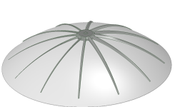
I drew up a revised version with the prop idea anyway, and the more accented wing shape for a visual, and because I got nothing better to do.

Prop top.png

If I could 3D print Styrofoam this could be half way there already!
 
APL said:
There's a lot of square inches under a wing, and 14 pounds for every one of them seems like a lot. Imagine a 1 square inch wing lifting 14 pounds. I assume that max could never actually be reached though, unless maybe as a prop?
IIUC how this works, to get 14PSI of lift from pressure on the bottom of the wing, you'd need vacuum on the top. ;)


Regarding creating airflow over the top, you might look up Coanda effect, I think it is called. (not sure if it is what you want to happen).
 
Bingo! Thanks amberwolf, that's exactly what I was looking for! I knew that this had to have been done before and that I was probably trying to reinvent the wheel. :| (Either that, or it simply had no chance of working.)

https://www.google.com/search?q=coanda+effect+aircraft&hl=en&tbm=isch&sxsrf=ALiCzsYnbmythkRN-P3UILLazXHrpeMiog%3A1671126542173&source=hp&biw=1536&bih=722&ei=Dl6bY9GuCLKbptQPttGOmA4&iflsig=AJiK0e8AAAAAY5tsHgYrLG2DulM0JpRZFAWI9rYkI90I&oq=coanda+effect&gs_lcp=CgNpbWcQARgBMgUIABCABDIFCAAQgAQyBQgAEIAEMgUIABCABDIFCAAQgAQyBQgAEIAEMgUIABCABDIFCAAQgAQyBQgAEIAEMgUIABCABDoECCMQJzoICAAQgAQQsQM6CAgAELEDEIMBUABYrB9gsENoAHAAeACAAa8BiAGiDpIBBDAuMTOYAQCgAQGqAQtnd3Mtd2l6LWltZw&sclient=img

There's probably nothing new in the aircraft field except in the high tech department. Duh.

Still, the Coanda effect links give me a whole new world of info to explore, .. so thanks for the word 'Coanda'. :thumb:
(That's the thing with Google, if you don't ask right, then you don't get.)

And I was just going to suggest that the disc probably doesn't need to be a wing shape at all, just a bowl .. smooth from the prop down, and that's what I'm seeing in these images.

Well shucks, I guess I have to stop and reboot, lot's of stuff to look through.

Thanks to both of you for all the awesome help and support so far! :bigthumb:

Coanda efffect flight.jpg

It works! https://www.youtube.com/watch?v=CBbPVB11Wis
 
Well, I like things that fly (as long as I am not riding in or on it)...but one of my very favorite things is failure analysis...of many things, but aircraft "incidents" as one of the most interesting. So I have learned a few uncommon things about them, but I have huge gaps in my knowledge about them as well. :oops:
 
I like things that hoover, I don't know if I would ever get around to a human size version, but you never know. One you could ride on would make an awesome leaf blower for the yard though! :D

On a more serious note, we can always use ideas for safety against things like floods, tsunamis, and earthquakes, (yep, we all need one of these in the garage). Coincides with an old idea of an electric parachute for high rises too,.. but that's pretty far out.

I know, I'm a dreamer.

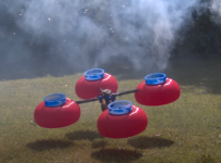
Anyway, it's like a kid in a candy store going through all this info, I guess the idea has been around forever and I missed it somehow. Here's a Coanda-copter from 1964!

Coanda copter 1964.jpg

I also like this one that uses an engine to provide both the air flow on top and thrust, or pressure, on the bottom as well, which makes sense to me. (as long as there's no turbulence under the dome).

Coanda top and bottom thrust.jpg

It made me wonder if the top air flow could be reversed over the disc and have the same effect? From the outside in, like a vacuum. An upside down impeller might draw the air inward over the disc to create the lift with less pressure, and add more bottom lift at the same time?

Reverse air flow impeller.png

Impellers probably don't work well in reverse though.
 
If you tried to suck instead of blow over the top, I think you would have much less air flow over the top of the "wing" as the air would tend to come in from all directions.

The Coanda-copter is cool. I wonder if it actually flew. I could see this being a useful design for hovering around trees/vegetation without having blades hitting things. Since we don't see designs like this in use, I assume it was inefficient or too expensive.
 
fechter said:
The Coanda-copter is cool. I wonder if it actually flew. I could see this being a useful design for hovering around trees/vegetation without having blades hitting things. Since we don't see designs like this in use, I assume it was inefficient or too expensive.

Boundary layer drag is a thing. It's one of the only things going on in this design. Might be more effective if laminar flow could be established over the lifting surface. That's kind of a tall order considering you'd be working with air that just passed through some kind of compressor.
 
Did understand lift over a wing but never gave this any thought or heard of Coanda effect! Well Axial it's educational.

EV's and flying have not been a good mix. Think wings will need to get bigger and use solar. fly slower with longer trips and keep cost down.
 
Yes, I wonder about the efficiency, there's got to be a reason why 4 prop drones won out. I'm thinking weight and the fact that they
are probably not very good in the wind. with all that area. But it all depends on use I guess, and being able to get close to things is
a big plus,.. your right.

Might be room for improvement though, with modern materials and motors, and maybe a few out of the box ideas.

Your right about the vague air flow over the disc, and I've been thinking about that. Seems like a shotgun approach to me and a natural airplane thing to do, but if we're just trying to disrupt air from the top surface to get less air pressure, then there might be a more direct and surgical way to do it. Working directly with the surface.

I'm not even sure if it needs to be a dome-disc,.. maybe a flat disc would work as long as a pressure differential can be achieved.

One way might be to introduce a static charge on the top (using a light tinfoil surface), that would release air molecules from the surface? Nobody likes HV though.

Another way might be to make the dome a thin hollow cross section and drill the top full of holes.
Then use the impeller to apply vacuum to the inside and draw air in through the holes, creating both air flow and vacuum on top.

Here's another attempt to work on the surface directly, using very thin composite blades to disrupt the air, or simply scrape it off.
Not for lift in the normal sense. Maybe could even be steel wires.

Contoured blade Coanda .png

Sorry for all the drawings, but I'm in the mood these days,.. the snow is blowing and the shop is an icebox.
(Wish I could shrink these screen shots, but I haven't figured it out yet.)
 
APL,

You should continue the project, beyond discussion and speculation. The Coanda lifter seen above is just a start, IMHO. Your counter-rotating impellers (or props) may be a game-changer, due to the cancellation of those pesky gyroscopic forces. I would not be surprised to find the earlier attempts got shot down due to the gyroscopic forces they included. The old vehicle pictured probably got good lift from the reduced air pressure of moving air across the dome, plus the "helicopter" lift of air being pushed down at the edges. In the case of counter-rotating props blasting air downward onto a curving cone, you may want to use two ducted fans, stacked, to increase the efficiency of the props. With the motor(s) mounted below the disk, the drive system would be very clean to the airflow.

You should be aware that with any helicopter, including your lifter, hovering at high altitudes will not be a simple matter of stopping to hover. The vehicle will start to sink in a high hover, with the same power applied, as the column of air below the craft goes further downward over time. More power must be added, to hold a stationary high hover. A little forward motion of the vehicle will be the simple cure there. Have fun!
 
APL said:
(Wish I could shrink these screen shots, but I haven't figured it out yet.)
The forum does that automatically when you upload pics.
 
Thanks red, I should build something relatively normal, I do tend to get carried away, ha!, and it's always fun to speculate.

I agree that the counter rotating impellers might be the best thing going on here, and I need to get back to that idea. I have to figure out how to get air to the bottom impeller yet, but do have an idea to work on.

Most of the Coanda lifters I've seen have used rudders around the diameter to counteract spin, so that sure cut's efficiency. You can just vary the rpm of the two impellers to rotate a disc.

I'm thinking that the axial is a good fit for that too since it's light, thin, naturally spins up to high rpm, and could use the cooling that the fans naturally have. Kind of a tall order to make though, so not a good thing to start with.

But ducted fans are easier and available for sure. Do you think they could work counter rotational in a duct?
 
APL said:
But ducted fans are easier and available for sure. Do you think they could work counter rotational in a duct?
APL,

Sure. For your testing model, check with the RC crew. They have lots of electric ducted fans, turning both left and right, on-the-shelf for you. Some RC ducted fans will have the motor built inside the hub, so you won't need driveshafts, or extra cooling.
 
I was thinking of both fans in the same duct, like this image. From what I gathered, the top prop is powered less than the bottom one. But yea, trying to power both fans without inner and outer drive shafts won't be very clean, and with the drive shafts the motors won't be cooled.

CF-Turbo-Figure-4_-3D-geometry-of-the-fan.png

Looking around at all the info on these Coanda lifters, I ran across this video that answers almost all the questions that we've been pondering, as he's already gone down the same road and done all the tests,.. including props and impellers. Very enlightening!

Youtube video; https://www.youtube.com/watch?v=Irp_vnmUWZ4

Youtube video.png

Bottom line is that they don't appear to be very efficient, although they do appear to work better at ground level, (which I like), and props look like they do work better.

Still, very interesting, and I've learned so much so far. There may still be room for improvement and I have a lot of stuff to look at yet, so who knows where this goes.

The idea of a 2 - 3 - or 4 prop drone is interesting in that it solves the spinning problem of a single, not nearly as cool though. :wink:
 
I think the interference in airflow between the different directions, especially as close to each other as those are, might cause turbulence problems, wasting energy as a lot of noise.

When I used to build computers for performance and low noise for my music studio stuff, I began hunting experimentally for the source of noise within airflow, and found that any fan that was near another object, especially grillework or heatsink fins, would have many times the amount of noise that one in "free air" did. So I removed all the grillework on the casings and fans, and removed all fans on heatsinks, instead creating cardboard ducting and/or baffles to redirect air past the heatsinks with a wide air path of more air volume but slower airflow (to reduce noise inside the ducting/etc.). The fans I reduced in speed (by reducing voltage to minimum that would start and run them), and used larger diameter fans to help move the same amount of air for the slower speed, and used less of them. I also used different speeds on each fan by a significant amount so there was no resonance between them that would make the casing or parts "thrum".

In all, this made the systems nearly silent, more than quiet enough to not show up in microphone recordings, and also not affect my listening to quiet passages during composition, editing, and mixing.

I also experimented with making extensions of the fan's actual "duct" around the blades, and moving the supports out of the airpath next to the blades, and putting them inches away down the tube (with another tube on the motor to mount to those supports). This made a significant difference to noise at high speed, but very little difference at slow speeds, if any.

I tried numerous other experiments to smooth airflow within the case itself, but found that generally the smoother airflow at heat exchange points, the less heat that would be removed from the parts that needed it--turbulence seemed to be required for this (but I never established that with certainty). But as long as the fans were nowhere near these areas, the system would still be quiet. So I just stuck with ducting the air over wide areas of heat generation, using large-surface-area thin-fin heatsinks with many parallel fins parallel to the airflow wherever possible, and added heatsinks to items that got warmer with the reduced airflow within the case to maintain the original normal temperature.


My takeaway from all this was that the clearer the path for the air, especially anywhere near the fan, the smoother the airflow probably was (as I couldn't see it), since it was quieter, and noise is often caused by turbulence (which also slows the airflow and wastes power).


So...its' an experiment you can try, with two fans with opposing blade designs counterrotating so they both cause airflow in the same direction, and put them closer to or farther away from each other, and see if the noise level or airflow goes up or down.

If they're within a duct (tube, etc) I expect the problem will get worse the closer they are to each other.
 
Thanks for your experience with props and noise levels amberwolf, I would think the props should be separated by some distance as well, and the noise level of these things has always sat uneasy with me. It would be nice to have a quiet lifter for once.

I have always liked the 'electric' DIY human lifter drones, and even think about what it would be like to have one,.. however brief the flight would be, but the noise level is really high. Not happy with all those blades nearby though. (Nor the cost $$)

I had hopes that a Coanda lifter might be a way around all that, but maybe not. The only two ways I've seen so far are the balloon, and the massive human powered drones, which of course, are not practical. Quiet though! :)

Atlas  human powered flight.jpg

The red Coanda drone shown in the video above seems to be quite heavy, I think he said it came in at 800+ grams, or roughly two pounds. I understand why he 3D printed the domes, but think they should have been lighter, since their purpose is mostly as a form. Maybe Styrofoam would have bought a lot more success.

The dome shape of the Coanda lifter seems to work 'something' like a balloon, with the shape and the higher pressure on the inner top surface, and I started to think of a balloon as a super light Coanda 'form', instead of a hard dome. It would only need air inside, but could be helium too. Not the direction I wanted to go, but an idea none the less.

Anyways, still giving it thought, but looking less like a build, unless I can find something really new to try. I can't see doing something that's already been done.
 
APL said:
The red Coanda drone shown in the video above seems to be quite heavy, I think he said it came in at 800+ grams, or roughly two pounds. I understand why he 3D printed the domes, but think they should have been lighter, since their purpose is mostly as a form. Maybe Styrofoam would have bought a lot more success.
Vacuform is really easy to do (once you do some practice runs to get the hang of it), and can be quite strong depending on the material used. If necessary, reinforcement ribs can be attached (glued, etc) inside the dome to hold it's shape under stress.

You can make a generic VF machine out of a goodwill airhockey table (to make the bed from) and some wood or old steel bedframe and some C-clamps (to hold your plastic sheets), old clothes dryer heating elements or even just a powerfully hot heat gun (to quickly and evenly melt the plastic sheet), and an airtank of sufficient volume you can use an air compressor to suck the air out of to use as a vacuum source. (a really powerful shopvac or similar can also be used, but if you have a good seal on bedframe and plasticholder the tank will do a faster better job). Other bits and bobs depending on the complexity of the form you're using and the detail you need, or how fancy you want to make the setup.
 
Back
Top