Bad design -- no kill switch

My bike is set up with an ebrake switch that has in 9K+ not failed me except in the no go mode. Just in case it did my controller is right under my seat and I installed, some have them already, a power switch for it that I can reach from my seat. It could be on the handlebars cuz as John and others have said it is very low amperage. In case both of those fail I have a battery switch, could be an Anderson or other connector type of jumper, that I can reach from my seat to disconnect the batts from the system. These three items are all very common and on many bikes if not most on the forum. Being able to pull the front wheel off the ground is a two edged sword it looks really cool but is very dangerous.
I hope you can figure something out that will make you feel safe again. Injuries make you cautious for awhile for good reason. Me I learned not to ride near full speed with slicks in the snow. Only took three months for my arms to heal from that crash. Helmets are good indeed.
 
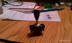
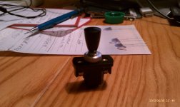
What about a marine grade kill switch in-line with the main lead from the battery to the controller like this:

In the on position - current flows

ON.jpg

In the off position - no current flows

OFF.jpg

I'm thinking to place it on the top bar near the headset. If you need to cut power you just slap it down = battery is disconnected from controller.

I think boats have these on them. I think high current flows through them. But I'm not sure.
 
You would need to check its current rating, but I doubt it is heavy enough.
Probably only 20 amps or so.

And you would then have to bring the main power leads up to the bars. Not good. More length means more losses, plus risk of breakage due flexing
 
Please check out my kill switch youtube.com/kerscycle

This switch controls the main 100 amp contactor. The switch has a spring loaded cover so a little bit of force to overcome the cam effect shuts the switch fast. In addition, I have the main positive power feed cable exposed so I could literally rip the wires out pulling the connector out of the battery.

I have a soft kill connected to my front brake communicating with an arduino.

If youre afraid of your bike that is not good sir. An idea just popped in my head to have a second microcontroller whos sole purpose is to monitor amps and switch states (brake switch). It would control a main contactor and make sure you 1) never exceed a current threshold 2) shutdown the contactor if it senses current and brake switch being made mutually

In addtion, in a sarcastic but sensical manner, set up a camera running facial recognition software to detect the 'oh shit' face and shut your bike off
 
has absolutely no basis in fact. The CA doesn't work this way and the failure mode you have ascribed to the CA simply cannot occur. It is electrically impossible for the CA in the stock configuration to source voltage to drive the throttle, it can only sink current to limit the voltage applied by the operator throttle (hence the terminology: 'limiting'). Only the operator throttle drives the controller, the CA cannot. The fundamental electrical design of the controller interface makes the CA intrinsically safe regardless of any potential firmware or processor failures.

I just wired my CA up wrong. When I wired it correctly I had FULL WOT. Unplugged the throttle. Still WOT. Unplugged the CA and the bike works as normal.
 
The stock CA V2 has a diode in line with the throttle connection so it can only sink current. It cannot possibly drive voltage into the controller throttle input.

The old style V2 controller interface also has a diode in line so there are actually two diodes in series blocking throttle voltage into the controller. The new 'large screen compatible' interface has no diode and was not in distribution at the time of this thread. However, when this new style is used with a V2, there still cannot be current flow into the controller because of the V2 internal series diode. This is why the new 'large screen' controller is plug-compatible with both V2 and V3 - the V2 has a diode and so can only 'limit', the V3 has no diode and so can 'control' the throttle. The circuit examples are

You don't provide any details of "correctly' and 'incorrectly' but something is wonky. It sounds to me like you have a new 'large screen compatible' controller and a CA V3 or a modified V2.

FWIW - Regarding non-stock CA configuration: Both the V2 and the V3 can be modified (by using alternate throttle connection pads on the PCB) to either 'have' or 'not have' a diode. This allows a V3 to be changed to only limit or a V2 to be changed to have Current Throttle like a V3...

Provide some details and I'm sure we can figure out what happened...
 
Not really sure what wiring I did wrong, but I do know that the only wires I hooked up correctly were the + and -

It's a stock v2 from around 5 years ago.

Anyways, crisis averted. Snipped the green speed control wire, and everything is back to normal. Fine by me because I never used the speed control function anyhow.
 
AhHa!

5yrs ago the V2 did not have the internal diode and relied on the controller diode. The new controllers don't have the diode, so this was the equivalent of a V3 hookup that controls the throttle instead of limiting it. Pretty easy to hook up V3-style Current throttle with that rig... :mrgreen:

Let me know it you want to use the CA LVC and other limiting - adding the diode internal to the CA is pretty easy.
 
Up higher you seem to want to be able to isolate the batteries.

See what Kepler did here with the EC5 connectors:
(scroll down half way to the blue surface plugs)
http://www.electricbike.com/stealth-hot-rod/

If so, consider the xt60 panel mounts. I've used them as bulk charge ports. They are ok in construction.
http://www.hobbyking.com/hobbyking/store/__43272__XT60_Panel_Mounting_Kit.html
 
Does your controller have a low voltage ignition switch wire ?, if so just put a motorcross style tether cut off switch in circuit with the ignition switch.
 
crea2k said:
Does your controller have a low voltage ignition switch wire ?, if so just put a motorcross style tether cut off switch in circuit with the ignition switch.

Most mc lanyards short to shut down a bike and are open for normal running so you will need to find a lanyard that is the opposite way around than the norm. they do how ever work very well when used connected to the e-brake.

I now make my own magnetic lanyards using a mini micro switch and I use the n/o and n/c connections to apply the ebrake and to also disconnect the throttle input ( 2 cutouts in one )

and I have a pullable link on the main battery for a master disconnect.

edit: Spose you could use the n/o connection to on the ignition wire instead of disconnecting the throttle.. this may actually be a better option .
 
Back
Top