You are using an out of date browser. It may not display this or other websites correctly.
You should upgrade or use an alternative browser.
You should upgrade or use an alternative browser.
Bafang BBS02B Speedometer Sensor
- Thread starter LewTwo
- Start date
LewTwo
1 MW
I was afraid of that. From what I have seen of the Bafang instruction they only use the "nominal rim size" which means their speed calculations are most likely wrong anyway.ebuilder said:You need it to satsify the controller or you will throw an error code.
Speedsensors are counters matched again time aka frequency which is programmed into the controller that correlates to speed and why you program in tire size which relates to 2 x pie x tire radius for every click on the counter.
The "connector and its wire" rub something wrong (like the tire).ebuilder said:Can you explain what you mean by rat tail interference?
No. The only Microshit Windoze machine I have is a old tablet primarily used for Kindle PC.ebuilder said:Can you mark up your drawing in MS Paint and post it?
I ordered a spare and here I go again taking a Bafang sensor apart to see what makes it "tick". This one is fairly simple. Full documentation to follow. The Chinese documentation I found says it is "dual pulse" .... but we all know how bad Chinese documentation is.
LewTwo
1 MW
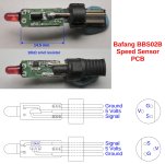
This thing was completely potted with some of rigid black stuff. It was actually easier to remove than the translucent gooey silly-shit in the Bafang PAS sensor I recently took apart. Cutting the case off and reducing the connector housing was a bit more challenging. There are only three electronic components in this sensor:
1) 10 k-ohm surface mount resistor
2) Red LED
3) 5 Volt hall effect sensor (has the number “128” inscribed on its side)
I have drawn a simplified layout (not nearly as many vias) of the top and bottom of the PCB as best I can figure it out. And yes that LED is connected to the signal line via the 10K Ohm resistor (not a mistake). I also used a flashlight to determine if there is a third layer in the middle … there is not.

I connected it up to my bench power supply set to 4.5 volts and 0.1 amps max. The recorded power draw was 0.003 to 0.004 amps per the power supply.
Then I connected a DMM between ground and the signal line. The DMM was set to read the voltage.
As Private Gomer Pyle used to say “Surprise, surprise, surprise”! When a magnet is passed over the hall sensor the signal line “TOGGLES” between zero volts and 3.1 volts.
What I think is happening:
When power is first applied the hall transistor is turned on and power passes through it to the signal line. The LED is off.
Pass the magnet over the sensor and Hall opens. The LED light turns on but the voltage drop across that 10 K Ohm resistor is HUGE and thus the meter reads zero.
If someone more electronic savvy has a better explanation then I am willing to listen.
Now to answer my second question:
Direction does not matter.
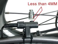
The sensor can be mounted back-asswards to get the rat-tail away from the tire/rim or other obstruction.
P.S.
If anyone needs or wants Higher Resolution image files then PM me.
1) 10 k-ohm surface mount resistor
2) Red LED
3) 5 Volt hall effect sensor (has the number “128” inscribed on its side)
I have drawn a simplified layout (not nearly as many vias) of the top and bottom of the PCB as best I can figure it out. And yes that LED is connected to the signal line via the 10K Ohm resistor (not a mistake). I also used a flashlight to determine if there is a third layer in the middle … there is not.

I connected it up to my bench power supply set to 4.5 volts and 0.1 amps max. The recorded power draw was 0.003 to 0.004 amps per the power supply.
Then I connected a DMM between ground and the signal line. The DMM was set to read the voltage.
As Private Gomer Pyle used to say “Surprise, surprise, surprise”! When a magnet is passed over the hall sensor the signal line “TOGGLES” between zero volts and 3.1 volts.
What I think is happening:
When power is first applied the hall transistor is turned on and power passes through it to the signal line. The LED is off.
Pass the magnet over the sensor and Hall opens. The LED light turns on but the voltage drop across that 10 K Ohm resistor is HUGE and thus the meter reads zero.
If someone more electronic savvy has a better explanation then I am willing to listen.
Now to answer my second question:
Direction does not matter.
The sensor can be mounted back-asswards to get the rat-tail away from the tire/rim or other obstruction.
P.S.
If anyone needs or wants Higher Resolution image files then PM me.
First, I'd like to say that I appreciate your disassembly and drawing up of various components like this; these are things that few people do and even fewer ever post up, and they can help tremendously when diagnosing problems in some cases (as they may show exactly how a particular thing works and what behavior can be expected under various failure modes).
More below:
It's also (LED+resistor) a pullup from ground to 5v, so that there is a voltage when the hall sensor is not triggered, for the controller to read. (the controller may also have an internal pullup, but if it doesn't, this does the job).
Depending on the sensor type (other than for throttles), on ebikes hall sensors are usually just open-collector. This means that when in their active state, they ground the output, but otherwise the output will be in a floating state. That's why there is a pullup (resistor+LED in this case) to 5v. (basically they act like a switch between ground and the signal wire--if the switch is on, it's grounded, otherwise it's no connection, so it reads whatever is connected to the signal line outside the hall sensor).
So when the magnet passes, it changes the state of the sensor to active, the sensor grounds the output so it goes to (about) zero volts (often no lower than about 0.3-0.8v).
During this time current now flows thru the LED and resistor and it lights the LED.
When the magnet is not passing it, the state is inactive, and the output floats so a voltage reading there will be whatever the pullup is connected to. In this case that's likely to be the supply voltage minus the LED's forward-voltage-drop, usually 1.2-1.4v or so. Since you're supplying 4.5v, and the LED drops 1.4v, you get 3.1v at the hall signal output pin.
The same process happens in motor UVW hall sensors (one for each phase, vs things like SIN/COS encoders, etc), except most of the motors use latching halls, so they remain in the state they are in until the opposite polarity field passes thru them (when they change to the other state), or power is cycled (when they reset to inactive state).
Speedo sensors probably aren't latching, and respond to *any* field polarity/direction as long as it is strong enough, but otherwise behave the same.
PAS sensors would be similar, except that they may use two sensors and may they have logic in them to take two sensors and detect the output direction by the timing between the two, and vary the output waveform to tell the controller about it.
More below:
The resistor is just a voltage dropping resistor to limit current thru the LED (since it can't take more than about a volt and a half or less across it, before current exceeds it's ability to handle and it overheats and fails).LewTwo said:And yes that LED is connected to the signal line via the 10K Ohm resistor (not a mistake).
It's also (LED+resistor) a pullup from ground to 5v, so that there is a voltage when the hall sensor is not triggered, for the controller to read. (the controller may also have an internal pullup, but if it doesn't, this does the job).
Then I connected a DMM between ground and the signal line. The DMM was set to read the voltage.
As Private Gomer Pyle used to say “Surprise, surprise, surprise”! When a magnet is passed over the hall sensor the signal line “TOGGLES” between zero volts and 3.1 volts.
Depending on the sensor type (other than for throttles), on ebikes hall sensors are usually just open-collector. This means that when in their active state, they ground the output, but otherwise the output will be in a floating state. That's why there is a pullup (resistor+LED in this case) to 5v. (basically they act like a switch between ground and the signal wire--if the switch is on, it's grounded, otherwise it's no connection, so it reads whatever is connected to the signal line outside the hall sensor).
So when the magnet passes, it changes the state of the sensor to active, the sensor grounds the output so it goes to (about) zero volts (often no lower than about 0.3-0.8v).
During this time current now flows thru the LED and resistor and it lights the LED.
When the magnet is not passing it, the state is inactive, and the output floats so a voltage reading there will be whatever the pullup is connected to. In this case that's likely to be the supply voltage minus the LED's forward-voltage-drop, usually 1.2-1.4v or so. Since you're supplying 4.5v, and the LED drops 1.4v, you get 3.1v at the hall signal output pin.
The same process happens in motor UVW hall sensors (one for each phase, vs things like SIN/COS encoders, etc), except most of the motors use latching halls, so they remain in the state they are in until the opposite polarity field passes thru them (when they change to the other state), or power is cycled (when they reset to inactive state).
Speedo sensors probably aren't latching, and respond to *any* field polarity/direction as long as it is strong enough, but otherwise behave the same.
PAS sensors would be similar, except that they may use two sensors and may they have logic in them to take two sensors and detect the output direction by the timing between the two, and vary the output waveform to tell the controller about it.
LewTwo
1 MW
Actually this appears to be a "latching" hall.
I went back and tested it three times to verify that ... because I did not believe it the first time.
I had to purchase a new sensor via Amazon to use on the bike.
I was pleasantly surprised to see that it actually appears to be a Bafang OEM part rather than a clone:
https://www.amazon.com/dp/B09PMSG41J

It did not have the M4 screw for the spoke magnet but maybe that was lost in shipping.
I went back and tested it three times to verify that ... because I did not believe it the first time.
I had to purchase a new sensor via Amazon to use on the bike.
I was pleasantly surprised to see that it actually appears to be a Bafang OEM part rather than a clone:
https://www.amazon.com/dp/B09PMSG41J

It did not have the M4 screw for the spoke magnet but maybe that was lost in shipping.
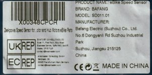
I like the "EVATOST CONSULTING" name... My mind says it should be pronounced EhvaToast.... :lol:
tomjasz
1 GW
some firmware versions will not run, others an error code, and yet another a one-time error and no more codes. we've been Bafanged...
tomjasz
1 GW
LewTwo said:This thing was completely potted with some of rigid black stuff. It was actually easier to remove than the translucent gooey silly-shit in the Bafang PAS sensor I recently took apart. Cutting the case off and reducing the connector housing was a bit more challenging. There are only three electronic components in this sensor:
1) 10 k-ohm surface mount resistor
2) Red LED
3) 5 Volt hall effect sensor (has the number “128” inscribed on its side)
I have drawn a simplified layout (not nearly as many vias) of the top and bottom of the PCB as best I can figure it out. And yes that LED is connected to the signal line via the 10K Ohm resistor (not a mistake). I also used a flashlight to determine if there is a third layer in the middle … there is not.
BBS02B Speed Sensor (2048).jpg
If anyone needs or wants Higher Resolution image files then PM me.
great post! thanks!!!!
Similar threads
- Replies
- 0
- Views
- 132
- Replies
- 22
- Views
- 547


