Battery Pack Build - A123 ANR26650M1A Cell (B-GRADE)

br549

10 W
Joined
Jan 24, 2010
Messages
66
I’m going to build my first LiFePo4 pack. I want to start by thanking everyone on this site for sharing their knowledge and experiences, without that I wouldn’t have known where to begin.

I’m going to start by building packs that I can assemble and disassemble for my initial testing to ensure the packs meet my needs before I commit to soldering or spot welding the packs together. I’m going to start out by building four 12v 4sx6p packs. I can then series those together into larger 36v and/or 48v packs. I’m using the thread below as my guide:

Building cylindrical battery pack for Dummy!
http://www.endless-sphere.com/forums/viewtopic.php?f=14&t=17912&start=0

I decided to build them 6p since the continuous discharge rate for these cells is 70A giving me at total of 420A. My largest controller can’t pull over 300A and the one I’ll be doing most of my testing with pulls a max of 150A so I’ll have plenty of cushion and won’t have to worry about accidently destroying them by pulling too many amps.

This is where it gets a little fuzzy, but one 12v 4sx6p pack should give me 60 Ah. My goal was to have at least the capacity of one Optima D34M battery which is rated at 55 Ah (C/20). My setup should be better than the Optima since an SLA can’t deliver its entire capacity when drained quickly (this Optima can’t put out more than 25 amps compared to my 420 amps continuous 720 amps max) so in my application the Ah for the SLA was probably much less than 55 Ah. Also the weight of my pack will be 3.9 lb compared to 43.5 lb for the Optima! Bottom line I hope to get a lot more distance with this setup.

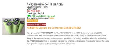
I purchased 108 cells for five bucks each, from this site http://www.buya123batteries.com the cells were listed as a discontinued item.

I was thinking about getting a Turnigy A-6-10 200W Balance charger & discharger to get the cells charged before putting them into the pack.

http://www.hobbyking.com/hobbyking/...y_A_6_10_200W_Balance_charger_discharger.html
 
br549 said:
...one 12v 4s6p pack should give me 60 Ah.

6p*2.3Ah = 13.8 Ah 4s*3.2v=12.8v 4s6p=176Wh

4 4s6p packs paralleled = 12.8v 55.2Ah 883Wh
4 4s6p packs in series = 51.2v (58.4 max)13.8Ah

Still less than half the weight. I replaced 12ah SLA with 4.6Ah A123.. at 25A A123 had more runtime, but the SLA were tired.

I've used a very similar charger eco-6 200w. Works fine but I've never pushed it above 8A.
 
br549 wrote:
I’m going to start by building packs that I can assemble and disassemble for my initial testing to ensure the packs meet my needs before I commit to soldering or spot welding the packs together. I’m going to start out by building four 12v 4sx6p packs. I can then series those together into larger 36v and/or 48v packs. I’m using the thread below as my guide

How do you plan on assemling the packs without solder or welding?
If pressure, I think it was not too long ago I read that A123s don't like that.
Not sure, it just stuck in my head.

Dan
 
RedLine19K said:
6p*2.3Ah = 13.8 Ah 4s*3.2v=12.8v 4s6p=176Wh

4 4s6p packs paralleled = 12.8v 55.2Ah 883Wh
4 4s6p packs in series = 51.2v (58.4 max)13.8Ah
Thanks for checking my calcs, I was incorrectly using 2.5Ah and not 2.3Ah.
 
DAND214 said:
How do you plan on assemling the packs without solder or welding?
Using Battery Clips from Mouser.com (Part # 534-209) attached to a Copper Strip from McMaster.com (Part # 8964K721) (see the link at the beginning of this thread). It should be just enough to hold the cells in place for the electrical connection but not put too much pressure on the actual cell itself. At first I was thinking about compressing them between copper strips only but that would have put too much pressure on the cells and probably prevented the cell from properly venting.

Here is another design that I found on another thread that doesn’t require welding so it is being done.

http://green.autoblog.com/2012/05/18/neal-saiki-claims-battery-breakthrough-gives-more-range-costs-l/

In the end I’ll probably take the packs to Battery Plus and have them spot weld them once I make sure they are configured and work they way I want.

If pressure, I think it was not too long ago I read that A123s don't like that.
You are correct, this is what A123 states:

  • Cell Support
    Secure the cells in place by supporting their outside cases, not their terminal ends. The vibration induced between the terminal ends and the rest of the case has been shown to be detrimental to the life of the cell, causing internal and external cell damage. The intercell terminations must be light enough not to cause vibration-induced damage to the cell.

    Never use pressure at the top and bottom of the cell to hold cells together in a way that leads to blocked cell vents. If the vents are blocked, the gas cannot exit the cell in case of cell failure. Cells shall be mounted in the application, in a way that will not interfere with the vent function on the cell.
 
I numbered each cell and checked the voltages


Cell Voltage
042 - 3.209
062 - 3.233
005 - 3.252
006 - 3.264
099 - 3.278
014 - 3.28
082 - 3.286
070 - 3.292
013 - 3.299
048 - 3.299
069 - 3.299
072 - 3.299
104 - 3.299
017 - 3.3
019 - 3.3
036 - 3.3
097 - 3.3
015 - 3.301
026 - 3.301
041 - 3.301
049 - 3.301
076 - 3.301
004 - 3.302
010 - 3.302
023 - 3.302
024 - 3.302
030 - 3.302
032 - 3.302
035 - 3.302
053 - 3.302
064 - 3.302
080 - 3.302
083 - 3.302
086 - 3.302
091 - 3.302
094 - 3.302
108 - 3.302
001 - 3.303
003 - 3.303
012 - 3.303
016 - 3.303
020 - 3.303
022 - 3.303
025 - 3.303
028 - 3.303
038 - 3.303
039 - 3.303
043 - 3.303
047 - 3.303
050 - 3.303
054 - 3.303
055 - 3.303
056 - 3.303
058 - 3.303
060 - 3.303
065 - 3.303
067 - 3.303
068 - 3.303
071 - 3.303
073 - 3.303
074 - 3.303
075 - 3.303
077 - 3.303
087 - 3.303
088 - 3.303
089 - 3.303
098 - 3.303
100 - 3.303
101 - 3.303
102 - 3.303
105 - 3.303
106 - 3.303
107 - 3.303
007 - 3.304
008 - 3.304
011 - 3.304
018 - 3.304
021 - 3.304
027 - 3.304
029 - 3.304
031 - 3.304
033 - 3.304
034 - 3.304
040 - 3.304
044 - 3.304
045 - 3.304
046 - 3.304
051 - 3.304
052 - 3.304
057 - 3.304
059 - 3.304
061 - 3.304
063 - 3.304
066 - 3.304
078 - 3.304
079 - 3.304
081 - 3.304
085 - 3.304
090 - 3.304
092 - 3.304
093 - 3.304
095 - 3.304
096 - 3.304
103 - 3.304
009 - 3.305
037 - 3.305
084 - 3.305
002 - 3.306
 
DAND214 said:
br549 wrote:
I’m going to start by building packs that I can assemble and disassemble for my initial testing to ensure the packs meet my needs before I commit to soldering or spot welding the packs together. I’m going to start out by building four 12v 4sx6p packs. I can then series those together into larger 36v and/or 48v packs. I’m using the thread below as my guide

How do you plan on assemling the packs without solder or welding?
If pressure, I think it was not too long ago I read that A123s don't like that.
Not sure, it just stuck in my head.

Dan

The A123 "Cylindrical Battery Pack Design, Validation, and Assembly Guide" document says this:
"Cell Support
Secure the cells in place by supporting their outside cases, not their terminal ends. The vibration induced between the terminal ends and the rest of the case has been shown to be detrimental to the life of the cell, causing internal and external cell damage. The intercell terminations must be light enough not to cause vibration-induced damage to the cell.

Never use pressure at the top and bottom of the cell to hold cells together in a way that leads to blocked cell vents. If the vents are blocked, the gas cannot exit the cell in case of cell failure. Cells shall be mounted in the application, in a way that will not interfere with the vent function on the cell."

"Thermal Events
Proper battery pack design is essential to allow the safety features of A123 Systems’ cells to function as designed.As a safety feature, overheating A123 cells vent gases to relieve dangerous pressure buildup to disperse into the environment. However, an improperly designed battery pack can prevent the gases from safely dispersing, or prevent the cells from venting altogether. Adding an ignition source to improperly-vented gases can create a dangerous thermal event. You must ventilate these expelled gasses from the environment itself after the gases are vented from the cell itself."

Given the above information, I think the battery clips are a good idea and one I have been considering as well. They should provide good contact, not transmit vibration into the ends, allow a cell to vent, and provide a convenient place to attach monitoring (or individual charging) leads. If you build a container that it is actually holding the cells (not the spring clips themselves) and have dividers between cells to draw heat to the outside it seems like you are on your way...
 
999zip999 said:
Look into how to make a spot welder here in the battery section sorry no link.
I've been looking at several DIY spot welders

Microwave Welder
[youtube]al45MXMp7e0[/youtube]

Capacitor Welder
[youtube]t3kwpQbVHBo[/youtube]

I also talked with a guy that worked at Battery Plus and he took me in back and showed me the battery welder that they use and actually welded a couple of batteries to show me how it worked. When I talked about building a battery pack for EV use he said he'd like to do one! I didn't ask what he'd charge to do up some packs. They sell people batteries and then build the packs for drills and such. Maybe I could put some Battery Plus advertising on the pack and get a discount on welding! Wouldn't be opposed to applying for a part time job there just to get access to the spot welder for off hour use! :D
 
I would not bother with diy welder. Proper ones give out double pulse and welds better and you want better welds for higher currents. I would look for someone to do that for me. This is what i did with my last battery. I have paid something like 30$ for 50 cell pack. They advised me that capacity checking is not what they do but rather check IR of each cell which to me makes sense.
The question i still have is how would you group cells with different IR. Lets assume i have cells with 30mOhm and 35mOhm resistance. How would one assemble the pack, would i need to put same resistance cells parallel or spread them in series? My assumption is that i would need to spread cells in series. Lets take for example a 10S5P pack. Say i have 10 cells with 35mOhm and 40 with 30mOhm. If i will put 2 5p with 35mOhm and the rest 8 5p of 30mOhm means that 2 cell banks in series will discharge differently from the rest but if i mix one 35mOhm cell in 5P bank with 4 cells that are 30mOhm and do that do all 10S it will discharge more evenly? What do you think about this aspect of pack building?
 
agniusim
i'd spread the high ohm cells around the outside of the pack where they should cool easier. they will want to heat faster, so the idea is to keep them cool and that should help them maintain amps.
Also you could find out years from now if they fail first or not. so an easy to check/service spot could be a plus.
i'd like to hear other ideas as this is a good Q.
 
I had Batteries Plus spot weld a small A123 M1 26650 pack back in 2009. It saved alot of hassle and kept the cells clear of my heavy duty soldering iron. The welds have lasted and I'm still using the pack. I also glued the cells together with "Goop" a mistake I realized when I needed to replace a cell last month!

The cells are a good deal at $5. Did the seller say what it was that made them "B" grade? Have you tested the capacity of any of the cells? Do they have any flaws you can see? The voltages are within spec...

Good luck with your project!
 
Personally i am not concerned about heating up as i tend to overbuild the pack so the current i draw is third or half that allowable on the cell.
 
agniusm said:
The question i still have is how would you group cells with different IR. Lets assume i have cells with 30mOhm and 35mOhm resistance.
I purchased my cells directly from A123 so I’m hoping they were manufactured close together and should have close to the same chemistry. I also purchased 12 extra cells so if some don’t match up I’m going to use them in a leaf blower and my iMow.
 
agniusm said:
Personally i am not concerned about heating up as i tend to overbuild the pack so the current i draw is third or half that allowable on the cell.

you seem to know a lot about this.
What is the cause of high ohms on a new cell?
What is the effect(s) ? Obviously this is bad, but in what way? Less capacity? shorter life? Or just slower discharge?
Anyone research this?
 
The way i understand it is if cells are of uneven IR they tend to drift more out of balance. now this is just what i think. Putting those high cells in series, spreading across the pack should minimize this effect, at least i think so? Anyone with real data?
 
silentflight said:
I had Batteries Plus spot weld a small A123 M1 26650 pack back in 2009. It saved alot of hassle and kept the cells clear of my heavy duty soldering iron.
I think I’m going to go the Batteries Plus route when I'm ready to commit to a pack size. I did get cheaper cells since I’m sure I’ll make some mistakes with these along the way. I’ll probably experiment soldering on a few after I practice on some old dead cells. I need to get a higher wattage iron and a bigger tip first.

The cells are a good deal at $5. Did the seller say what it was that made them "B" grade?
Site said they were discontinued items.
A123BatteryPurchase03.PNG
Have you tested the capacity of any of the cells?
Haven’t checked capacity or internal resistance yet, I’m reading up on how to do it.
Do they have any flaws you can see? The voltages are within spec...
No flaws that I can see, was happy to see all the voltages checked out.
 
An easy to service pack that will last for years could be made with nut + bolt terminals. Before welding on tabs, drill them for a small bolts, like 6-32 or 8-32 for higher amps. One cell could be bolted to the next, or a wiring harness could be made.
 
agniusm said:
The way i understand it is if cells are of uneven IR they tend to drift more out of balance. now this is just what i think. Putting those high cells in series, spreading across the pack should minimize this effect, at least i think so? Anyone with real data?
this is so easy to test!
i'd put them in series with good cells on a load tester and measure voltage every few minutes at your expected amps. then estimate how many high ohm are needed to equal the low ohm. then test this combo.
might be a parallel pack needs an extra cell or 2 for a much closer balance.
YOU do have a load tester, right?
A load tester is #2, right behind a DVM. Without these cheap simple devices, owning an ev is pretty much hopeless :roll: :D
 
heya br549
i'm considering a build with these cells as well. good thread , interesting designs- but i plan on spot welding these, dont solder to these cells.
building a pack this way will take some and careful planning if you want it to last. once you figure out howto measure IR/capacity, make sure you match the cells that have close ratings. dont mix and match.
also thermal management is important- you want uniform heat spread. i've been trying to find a foam for this job.

good luck with your build
 
davec said:
i'm considering a build with these cells as well. good thread , interesting designs- but i plan on spot welding these
How are you planning on doing the spot welds?
once you figure out howto measure IR/capacity, make sure you match the cells that have close ratings
I purchased a Thunder AC680 charger. As luck would have it my laptop batteries started failing so I busted open the pack and decided to figure out the capacity on these batteries instead of experimenting on my new ones. These are Samsung ICR18650-26C SDI 8B3 LiPo batteries.

laptop01.jpg

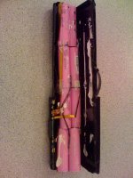
I carefully cut the pack apart leaving four separate 2p packs. I charged the packs and then discharged them. My charger can discharge up to 2 amps but when I hit the cells with 2 amps the voltage dropped below the LiPo minimum 3 volt cut-off and the charger safely dropped the discharge rate to .03 amps (not good if I was going to discharge these during my lifetime). I found out I could discharge at 1.5 amps and keep the batteries above 3v and it wouldn’t drop the batteries to the lower rate.

laptop02.jpg

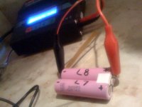
Now my goal was to find the weak cell(s). I thought I could charge and discharge individual cells and find my weak cell(s) by connecting the cable ends to each individual battery (even though the two cells were still hooked up in parallel). After some charges and discharges this looks like it’s not going to be the case, it appears to be charging and discharging both cells together. What this tells me is that if I have one bad cell in the 4s 5p pack I’m building I won’t be able to detect a bad cell without breaking the 5p pack apart into individual cells.

laptop03.jpg
 
hey br, based on that link, bmi designed a pretty crafty solder free plastic mold, i like that design. that is one route if one can fabricate molds like that, i sure cant.... regarding spot welding , i am fortunate to know a few local battery repair centres/ here who build commercial batteries- i pay for their time to help me spot weld copper tabs. it's advisable you find someone local as well. a good spot welder is out of price range for a DYI project.

thermal management is the most challenging aspect in your project. copper tabs are nice since they conduct power and heat at the terminals. heat makes cells age and increases IR. the trick is you wanto equalize the heat transfer so all the cells share the same heat which will make all the cells age @ same rate . another trick is to put the high ir cells on the outer end of the pack, and the colder on the inner that way it will distribute better. you may also use ir/ to make sure there's a good balance. some even use PCM material between cells to deal with this problem. there's also some foam you can use but i can't find any..... if you can keep the heat even your golden. if you can't some cells will get hot, these hot cells will have an develop a high IR, in a parallel config uneven IR is bad news. without good TH, your pack wont last

some tips

Cell Support
Secure the cells in place by supporting their outside cases, not their terminal ends. The vibration induced between the terminal ends and the rest of the case has been shown to be detrimental to the life of the cell, causing internal and external cell damage. The intercell terminations must be light enough not to cause vibration-induced damage to the cell.

One should always try to avoid exposing batteries to heat. This is partly because the cell
chemistry may become unstable if the temperature is too high, which can lead to venting and
possibly fire/explosion. Elevated temperatures accelerate the normal chemical processes taking
place in the battery cell, leading to cell aging and loss of capacity.
Heat can either be generated by the cell itself (decomposition,
internal short circuits and also during normal usage) or come from
an external source. Uneven heat across the cells in a battery pack
will cause the cells to age at different rates, which can lead to
problems in cell balancing. Cell balancing relates to how cells
perform together inside a battery pack. The greater the spread in max/min cell capacities, the
quicker a battery pack will lose capacity and fail. This is why, during battery pack assembly,
much care is taken to choose cells whose capacity and impedance are well matched
 
Back
Top