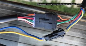
The pictures always help, just like being there. Like the easier and safer way to disconnect the brake switches if needed. I.E. undo the single connector at the controller.
And do to your efforts have a fair understanding of the wiring.
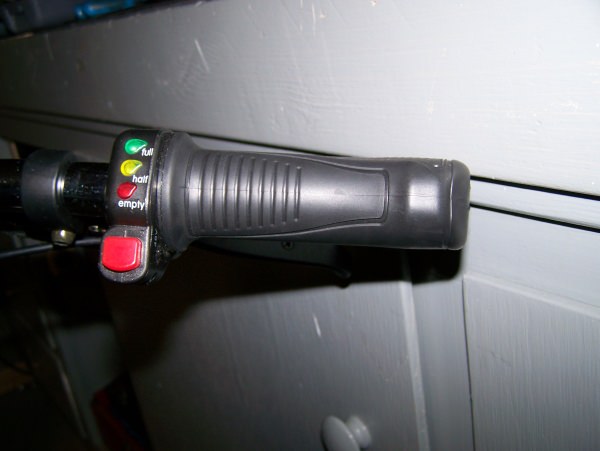
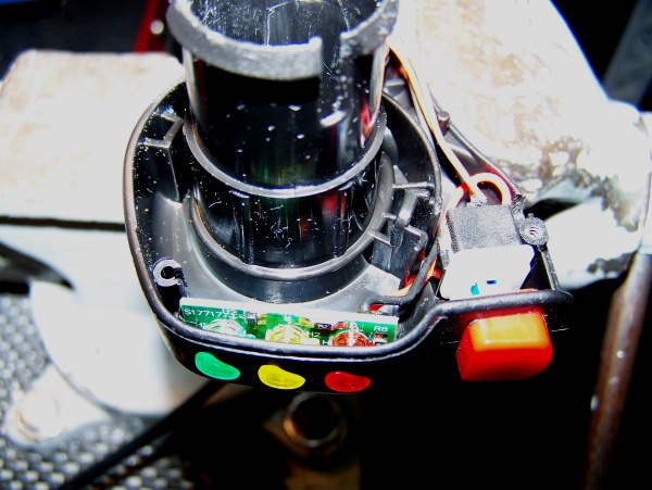
When I reference "throttle assembly" during testing, this refers to the throttle, throttle switch, and LED PCB. I.E. Everything contained in the throttle proper.
So I'd like to give some insight on my
reasoning which may help. (may get long winded... hang on)
Note that much has been provided and resolved already, with this providing an over view of known and still unknown till now.
Keep in mind the words...
possible and
probable. The first being yes, or no. The latter, on a scale.
If anything mentioned is inaccurate, please offer correction.
Identify the problem.
Hey, blinking lights of the wrong color expected is pretty up front.
")
More specifically...
Full battery power on BROWN wire with battery key switch turned on - Normal.
Slow rise to full voltage on BROWN wire - slow is relative... but seems to be Abnormal.
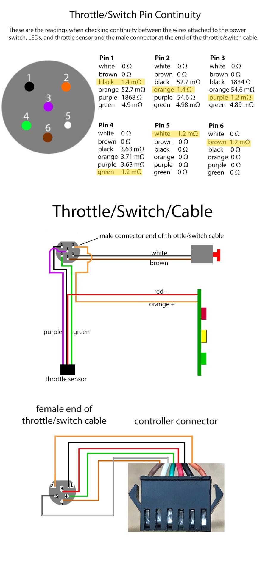
Somewhat erratic voltage oscillation on the BROWN, WHITE, and ORANGE wires
after the throttle switch is turned "on" - ABNORMAL. For future reference I'm going to call this "blinking".
As mentioned, a blinking RED LED indicator. I.E. Not only blinking, but of a relatively LOW voltage indication.
So you have to ask yourself, what could cause these symptoms?
These have been my general working hypotheses...
1) Lack of current from the battery when the controller is powered up.
2) Something shorted after the throttle switch, possibly in the throttle assembly itself.
3) Short in controller circuitry.
4) Error indication.
In troubleshooting you look or choose the most probable solution first to pursue, which eventually may guide you elsewhere.
You also get to choose the direction and jumps made along a path of understanding. I.E. In this case, you could start at the battery output, the throttle assembly, or in the middle so to speak. And travel forward or backward electrically speaking from those points.
The goal is to find where and how to make the blinking stop.(isolate) And then find out what is causing it, or why?
So let's look at the possibilities in depth...
1) Lack of current from the battery when controller powered up.
From the previous discussions in this thread, I thought this to be resolved. Right now it's at the top of my list. And what I would recommend checking for first.
Why?
You can have voltage
potential at two test points. I.E. The battery to controller connection. But you don't know how much potential, or specifically, the current
capabilities at that point. Often a voltage reading is taken, and after receiving a high voltage reading. It may be assumed to be full power. But can be what I call a "phantom" or ghost voltage. Voltage that has no actual power behind it. Good meters have built in impedance or resistance to counter such erroneous readings. But if just enough power is "leaking" through, it may be deceiving.
This would fit... the problem started after a blown inline charging fuse. And give the controller circuitry enough power to start up, but not enough to keep going. I.E. Cycle or blink.
To eliminate this possibility, do this test...
Modified from the original request, do to the change in order preference to the other tests. (probability ranking)
CAREFULLY check the voltage input at the battery to controller PCB terminals (often large Black and Red wires). Is full battery voltage steady there with all wiring normal, and system powered up. (blinking showed still be happening on the brown wire.
This is to verify that full battery capability is present at the power input connection to the controller after system is powered up.
If O.K. try the other ones...
TommyCat said:
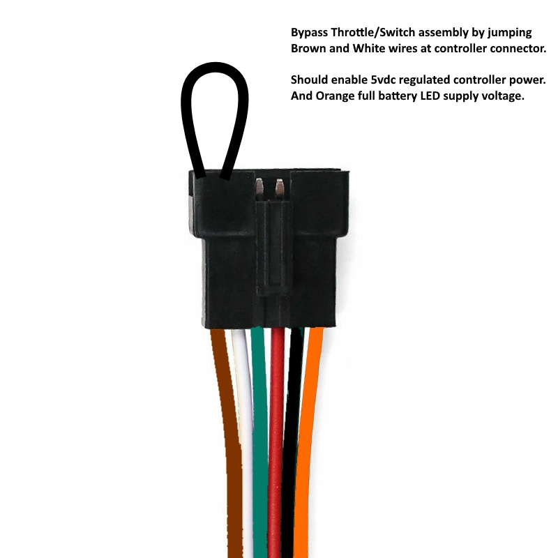
The bypass test is done with the connector going to the throttle assembly left disconnected.
Having the jumper on the controller connection side only. This will isolate the throttle assembly from the controller, eliminating it from being the possible source of the problem.
Then test for the intermittent voltage power on the BROWN wire.
I don't expect this to allow the motor to operate, or to fix the system. It's just a step taken toward the process of elimination.
And also if the BROWN wire still "blinks" even after the throttle assembly is disconnected and bypassed. And input power to controller is good and steady. Try disconnecting the brake connector. Low probability, but easy to check.
Out of time now... if you feel this is a benefit, I'll continue on the the other hypothesis if requested. Hopefully with the new tests we'll be closer to resolution.
Any questions?
Looking forward to the test results.
Don't mean to be a boar, but sometimes the why of what is asked as far as testing goes, is as important to know, as the test.
You can't fix, what you don't understand.