Battery won’t charge.

rick_p

100 W
Joined
Feb 16, 2021
Messages
260
Location
Los Angeles
I would like to resurrect my old ebike that was working until I had a battery problem. One day I plugged in the charger and nothing, it wouldn’t go into charge mode. I unplugged the charger and checked the fuse, it was blown, so I replaced it with the same exact type and amp rating. I plugged in the charger and the charger went into charge mode for about a second, but then it almost instantly stopped charging went went back into idle mode. I knew there is circuit protection inside the battery box so I unplugged, and removed the battery pack from the case to inspect. All the wiring appears intact (no visible damage) and the circuit boards don’t have any visible signs of short circuiting. Is this a hopeless case? Meaning, is it a case of there are no user replaceable parts at this point, or is there anything else I can check? The cells were probably around midway through their life span, I was still getting around 20 miles out of a charge before the failure, so it would be nice to get this bike back on the road if I don’t have to buy a new battery for it.
 
Is there a safe way to bypass the BMS to test drive the bike and check the battery's current distance capability? I wouldn't attempt to charge it that way, but I assume the BMS isn't used during operation and is only used during charging, or is that an incorrect assumption?
 
I think BMS is used during operation. At least on my old pack lifepo4 I can tell by warmth of it.
You could charge, as many suggest, each Lithium-Ion series with makeshift old cell phones and digital camera wires, about 4.2 v. Amberwolf and others suggest an old cellphone charger converted and applied to each series or individual cell. Or you can get a li-on 4.2v type charger. Of course, be careful. This might allow you to test ride it, but is not a permanent fix if BMS is truly damaged. Some have suggested that charging per each series or cells can stabilize the pack so the BMS can then work properly. In other words, if the pack is far out of balance, you need to balance it yourself and hope the bms can then take over.
 
The BMS is definitely used during discharge, and I for one would not use the battery regularly until replaced.
That said, others use a battery without BMS. Manually maintaining cell charges and added safety devices.
But for purely TESTING purposes, probably doable. But is it wise to do so? Or in your case needed? Seeing the current condition of your cell charges. Perhaps I missed something there...

I'm going to let the battery/BMS experts take over here, as it's out of my wheelhouse.

The last suggestion I have is to try a reset with your fuses removed, checking the output. (before the fuse) Then just installing the discharge one first to try. This is to verify no shorts or problems in the wiring past the BMS.


Just something I ran across... not an endorsement.

bms-variants.svg


as seen here...
https://vanderworp.org/battery-management-system-bms/
 
Maybe you should just buy another battery. The prices seem lower than 10 years ago.
 
Verify that the indicated voltage for each group was 4.71, and not 4.21. The second reading would indicate a significant issue, and/or a slightly inaccurate DVM. Should be 4.20.

The FIRST reading would indicate an EXTREMELY DANGEROUS situation and severe hazard of destructive fire.

Several readings reported would tend to indicate an uncertain or inconsistent connection of DVM leads while testing. Very easy to do. Do each test until you get the same readings THREE (3) times in a row.

Note also that a controller disconnected from battery will retain indications of power for a fair amount of time after removal of battery cables. Will not sustain much output other than lighting up of a few LEDs, but this makes these same LEDs unreliable indicators.

Battery voltage should NOT ramp up slowly tested directly at outputs. BMS only item present in the chain which could cause this. Previously blown fuse on charging input, observed problems follow this event.
 
RTLSHIP said:
I think BMS is used during operation. At least on my old pack lifepo4 I can tell by warmth of it.
Good to know, thanks for posting.
RTLSHIP said:
You could charge, as many suggest, each Lithium-Ion series with makeshift old cell phones and digital camera wires…
I can no longer change the title of this topic, but charging isn’t really the issue anymore, it’s whatever else is wrong with the battery.

TommyCat said:
The BMS is definitely used during discharge, and I for one would not use the battery regularly until replaced.
That said, others use a battery without BMS. Manually maintaining cell charges and added safety devices.
But for purely TESTING purposes, probably doable. But is it wise to do so? Or in your case needed? Seeing the current condition of your cell charges. Perhaps I missed something there...
I agree, probably not wise and probably wouldn’t tell me very much anyway.

TommyCat said:
I'm going to let the battery/BMS experts take over here, as it's out of my wheelhouse.
The last suggestion I have is to try a reset with your fuses removed, checking the output. (before the fuse) Then just installing the discharge one first to try. This is to verify no shorts or problems in the wiring past the BMS.
I’ll do this test, it’s easy enough to do.

TommyCat said:
Just something I ran across... not an endorsement. (Images of BMS wiring diagrams and how to bypass it, scroll up to see)
These are hugely helpful. As noted, I’m going to skip the bypass test and move on. I decided to remove as much of the foam tape and plastic protection covers as possible to get a better understanding of the wiring. Doing so made a huge difference, they are very telling and along with the diagrams you posted, I should not have a problem wiring up a new BMS. I’ll post pictures.

RTLSHIP said:
Maybe you should just buy another battery. The prices seem lower than 10 years ago.
What fun would that be!!! I’m only joking of course, but half of what we say in jest ;)
To your point, one could put way more time and energy into something that will never have a worthwhile return on (time) investment. And if this were a situation where this bike was my mode of transportation to get to work, then I would already be way past that point, I would have ordered a battery the minute I figured out the battery was definitely the source of the problem. But there is also a level of enjoyment one gets from working on these things, and a level of satisfaction when you succeed with a repair, and lastly, it’s such a great learning experience. All of the latter is where I’m at with this, it’s not about saving money or time, it’s about enjoying what my wife calls “tinkering” and learning how to work on and solve ebike problems. Also to your point though, prices have come way down.

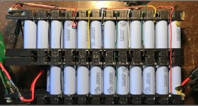
There are a total of 65 individual cells in this 13s battery, almost all of the balance wires are visible in the photo.
Battery overview shot.jpg
 
I was trying to figure out if my battery has a 13s or 14s configuration, then I found this great article written by SPINNINGMAGNETS: https://www.electricbike.com/introduction-battery-design-1/

As you can probably make out from the photos above, there are 65 individual cells, which appear to be configured in 6 banks of 10 parallel cells plus one bank of 5 parallel cells, but that may be deceptive because there are 14 balance wires, and what I learned from the article linked above is "the number of balance wires is the number of banks in the series plus one" and my BMS has 14 wires, so the configuration has to be a 13s, which means there are 13 banks in the series. I have to look at it some more to figure out how it has more banks than it appears, but in the end it doesn't really matter because I now know that I need a BMS with a 13s configuration to replace mine.

I'm also curious about the reason for not using banks with all the same number of cells, such as 5 banks of 13 cells, but I think it has something to do with achieving a nominal 48 when all of the banks are put into a series. If I figure that out, I'll post why.

Considering my goal is to buy the right BMS to attempt to repair my battery, all that really matters are three things...

1. The total nominal voltage, which is 48 volts
2. The total amperage, the article covers how to calculate this but I haven't got that far yet.
3. The number of banks in the series, which I know is 13 because my existing BMS has 14 wires.

My BMS also has ports for a key switch. It would be nice to find one that has this nice feature, but I could live without it.
 
rick_p said:
There are a total of 65 cells, there are 6 banks of 10 cells, and 1 bank of 5 cells. Is this enough information to determine if this is a 13s or 14s battery?

OK ... I will take a shot at this.

For those that enjoy pixel peeping I have a jpg.
For all others please see the PDF file.
For those that have DWG compatible CAD software see the ZIP file.

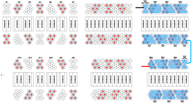
Samsung ICR1865-22P Battery Pack 00.png

You have a 13S5P pack made of Samsung IRC18650-22 cells (see PDF for specs). That is 13 groups connected in series (as Fatty so correctly concluded previously). Each one of those groups has five cells. In your pack those happens to be divided into two banks (one with seven groups and the other with 6 groups). That is the first diagram. Note the positive and negative marking for each cell.

Now slide all the cells in each bank together. That is the second diagram.

Lastly put terminal pads on the top and bottom of of each group to make the electrical connections. Those are 'spot welded' in place. Noted the connection between the two banks (light blue). That is the third diagram. Someone spent a lot effort and money making the proper dies to punch out those terminal pads.

The main negative battery lead (hopefully black) should be attached to the first terminal pad of the first bank (shown in black on the last diagram). This is ALSO where the negative (hopefully black --- apears yours may be yellow) balance lead should be connected. Each successive balance lead is connected to the next terminal pad. Lastly the the main positive battery lead (hopefully red) should be attached to the last terminal pad of the second bank (shown in red on the last diagram).

Hopefully someone will correct me if I have made a mistake :wink:
 

Attachments

  • Samsung ICR1865-22P Battery Pack.pdf
    262.9 KB · Views: 13
  • Battery Layout 10 (18650).dwg.zip
    67.1 KB · Views: 8
WOW! This is so incredibly helpful. It not only sheds light on how there are 13 groups when there are 6 banks of 10 cells and 1 bank of 5 cells, it also can be used (on page 5 of the PDF) to verify the locations of all the balance wires to ensure I wire up a replacement BMS correctly.

One question I have is, on page 2, under Nominal Specifications, it gives a specification for Max, Discharge Current of 10A. Can this be used to calculate what amp rating I need the BMS to support? Example: 5P X 10A = 50A rated BMS
 
rick_p said:
One question I have is, on page 2, under Nominal Specifications, it gives a specification for Max, Discharge Current of 10A. Can this be used to calculate what amp rating I need the BMS to support? Example: 5P X 10A = 50A rated BMS

Negatory. You have the calculation correct but think of it as more like the max number of dollars you have in your wallet. The question is how much is the controller/motor going to ask for your ride. Not really an area I am qualified in and it varies greatly. Someone like Amberwolf can give you better advice along those lines. Given no other information I figure 1000 to 1200 watts for a normal street/comuter E-Bike (1000 watts / 50 volts = 20 Amps).
 
rick_p said:
...when there are 6 banks of 10 cells and 1 bank of 5 cells...

This is a really confusing way to describe it. What you are describing by a “bank of 10 cells” is actually a 5 cells in parallel in series with another 5 cells in parallel. And depending on which side you look at the pack from these “banks” will change if you are basing it on the connections between cells.

So much easier to think of it as 13 groups of 5 cells, which is what it actually is. Then each parallel group of 5 can be thought of as a single cell of greater capacity.
 
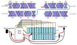
I mapped out the existing wiring of my battery pack. Each balance wire is numbered according to the spec sheet provided by LewTwo to ensure that I match them up properly with the new BMS. After reviewing the document on these packs I realized the photo I posted a few days ago stating the "polarity" of the wires was all wrong, so I removed it to hopefully prevent steering anybody wrong. I made other incorrect assumptions as well, but I didn't delete that text because it was later clarified by LewTwo and Blacklite, I can only hope that anyone reading this thread is careful enough to read it all if they plan to replace their BMS.
Battery and BMS Wires Numbered.jpg
Please view the image full size so you can see the numbering and let me know if this looks correct.
 
AngryBob said:
Verify that the indicated voltage for each group was 4.71, and not 4.21. The second reading would indicate a significant issue, and/or a slightly inaccurate DVM. Should be 4.20.

The FIRST reading would indicate an EXTREMELY DANGEROUS situation and severe hazard of destructive fire.
I double checked this, I transposed the numbers, they are all 4.17 volts.
 
I just updated the picture of the BMS wiring to include the Balance Lead Numbers. The numbers are small so please use the link below to view the image full size for a better look. Please let me know if it looks correct. Thank you
https://endless-sphere.com/forums/download/file.php?id=291312
 
Back
Top