BMS Battery Alloy Shell Charger Problems

dnmun said:
rui, can you tell what size that resistor is that burned up? maybe someone else has the same charger open and can read the label for you for the capacitor. it may be symmetric with another identical one there, also same with the resistor. i noticed they have identical circuits for each of those transistors, if these are in that loop.
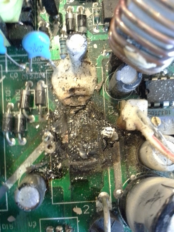
sorry for late reply. it is 2.2ohm ±1% (red, red, black, silver, brown) position is R20.
Now, the cap is positioned C11
thanks
 
mine, from here. :lol:
file.php

file.php

worth replacing the cap, or is she toast?
 
you coulda made toast with that one. what size cap? maybe someone watching here has a nichicon but i bet you have local electronic stores there who carry them. it was hot for a long time because the pcb has burned through too. easy when you can see the defective parts. this is the bulk charger for your lipo?
 
Wow that looks like a lot of power went where it shouldn't have. Sorry i cannot help, just getting more worried about my 600 EMC, which is very similar to yours.
 
i think you can replace the cap and see what it does... if you can buy the same rating capacitor then test it, as far as i know, the local electronic shop capacitor should be much better quality then the one from china...lol
 
What I am doing with these chargers now is taking down the amps by 20% as like with everything you get from China it's always on the limit of what it can do. Bring the amps output down a bit by adjusting the correct potentiometer and get a lot longer life from them.

They do not like vibrations either.
 
Spacey said:
...snip... Bring the amps output down a bit by adjusting the correct potentiometer and get a lot longer life from them.

Can we hook-up an old "Cycle annalyst" between the charger and batteries to monitor it correctly?
 
the doc puts an ammeter on the output of his charger, built in. you can use the ammeter in your voltmeter in line with the output to see how much current it puts out.

what happened to GC's cap looks like it just was poorly made, which can happen, and may have been running close to it's max voltage and then started leaking until it overheated from leaking charge internally until it failed. you can see that the heat was generated close to the legs end for a long time since it cooked the pcb underneath. i don't think it failed because of the current output of the charger. jmho.
 
@GCinDC: I can see that the inductor next to the cap also got so hot that it burned off it's enamel. You might want to re-insulate it, so that it can't accidentally short against something (or so you can't do any damage to it or yourself while you have it open while it's running, if you ever do that for any reason).


recumbent said:
Can we hook-up an old "Cycle annalyst" between the charger and batteries to monitor it correctly?
I use my CA to monitor charging, so that I know if my pack actually got back in as much as I used up (in case the charger fails ot fully charge it for some reason).
 
you can almost see how the flame was shooting outa the side of the capacitor and left all that soot on the inductor. even the fan cable has evidence of the scorching on the red insulating sheath, and i bet the side of the fan plug is almost melted. whatta blowout. examine the small cap next to it too in case it was damaged, but the inductor and trimpots should be ok, imo.
 
pgt400 said:
Did anyone figure out which pots adjust current and voltage on these unit? I have been using one for over a year now with no problems.
don't have pic, but it's tiny, very close behind AC in i think..

you really think mine's fixable with the board like that?
 
i would expect you can replace the cap and go with it. but the charred pcb may conduct electricity so it would still be shorted between the legs. if that is the only cap on those traces, you can measure the resistance between them when you take the cap off. but there is also gonna be a drain down resistor, about 5k usually across the traces somewhere, so unsolder that first and lift one end before measuring the resistance between the traces, if no short, then go with new cap.
 
I am surprised that nobody mentioned here cooling issue.
China power supplies/chargers have often simply not enough colling, namely fans are too tiny for amout of heat components generate especially switching FETs/Mostets.
When you want to pump 18A amps at 43V you better make sure those semiconductors/cups/ colis have enough cooling.
In all of my China-designed chargers I changed factory blowers with much more powerfull. I had switching MOSFETs heat up so much that they desolder themseves from the board. I provided real blast of cool air which solved problem of overheating semiconductors.
Now if you have fake switching semiconductors in you China switch-mode charger problem of cooling is even more critical.
Even before first charging try determine if they are fake and if so replace with genuine ones to start with.
Don't just connect battery and start drawing like 20A from this thing before those mods.
 
personally BMSBattery does not have this problem. from my experience with them (3 different chargers) mine was charged outdoor where average temp is around 10-15C and never charged for more than 2hrs. yet still cap blew up (fets never failed me so far)
 
don't tell me switching MOSFETs/FETs don't get hot??
Heat is amajor problem of failing electronics especially switch mode electronics and if you had fake semiconductors used with high R while on you have even more heat to disperse. Just by touching enclosure - it does tell .
Just caps blew-I don't belive just caps, there must had been more to that. Caps are no exception from electronic components , they are temp. rated also for a reason.
Heat destroy caps also.
 
actually, from my experience, the active device (transistor) that gets the hottest is the high speed diode, the schottky diode in the output. the power mosfets in the front end seem to handle the current ok. same for those push pull transistors.

i think broken traces or blown ICLs and fuses are the most common failure, and the caps just don't seem to be made to the same specs as western devices it seems. no doubt cooler is better, but that may not be what causes the caps to fail. maybe just poor quality control. maybe that's why they add that inductor in series, to reduce the pulses of current from the diode into the output cap so it doesn't get as hot. lower magnitude of the current pulses times the ESR (equivalent series resistance) means less heat. that is just speculation on my part.
 
can y'all see this image? i unsoldered the coil (what's that called?), below which the board was blown (not under the cap).
20120428_084625.jpg


and the bottom of the coil:
20120428_084618.jpg

could that have shorted?

this thing got thrown in and out of the backpack hundreds of times...
 
it may have shorted, there is a trace underneath it too which goes up to those diodes D11 and D12. if the toroid coil shorted to the trace through the iron ring, that may have caused the capacitor to blow up, did you check continuity between the copper and the iron?
 
To me, that looks like the cap was shorted internally, pulling so much current thru the inductor that the inductor overheated and burned like that. Hard to say for sure, though.
 
My guess - the inductor was saturated, (even though it is designed to run in continuous mode in a forward converter) and wasn't filtering the current pulses to the capacitor (that is its purpose) - the cap wasn't specc'ed to take that sort of ripple current, and committed suicide.

This is a good reason why you don't play with the settings too much on these without scoping them properly - you change the properties of the circuit, and your component values are wrong for the application. Turn the voltage up, bad things happen.

The maths behind these is a lot more complicated than most of us would like, trust me :)

I could post some up, but it may make your head do something similar to that cap :)
 
is there voltage coming out of the schottky diodes to the cap? past the cap?
<edit, finally read your comment, it is not the cap but the coil i though had the open trace underneath>
i was looking at your picture and i thought maybe the trace under the coil had broken, where it was burned, under the coil. i wonder if it would help for you to just use little wires bridging the traces in that region baby wire is fine. but that's a lotta charcoal. gotta be fragile.

i expect the small 5V cap is for stability in some feedback signal to the op amp over there. the voltage does go through that wire wrapped around the toroid, right? from the schottky diode to the positive output ? and i 'll look at the other pictures
 
hi guys, does anyone know what was the rating for capacitor which blew up??
The charger is BMSBattery 400w charger. C11 is the one which blew
View attachment 1
2012042006580000.jpg
thanks
 
Back
Top