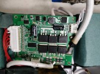
I have a Hailong 36V 23Ah pack from Grin, that came with a 40A BMS. This is my first battery with a bms. https://ebikes.ca/b3623-lim-dt.html
I wanted to see if I could push it higher than 40A for "short periods", and hopefully modify the most limiting components.
What parts should I check for?
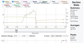
I started tweaking my controller, increasing the battery limit, but the BMS never shut the battery off. I went all the way to 70A and the battery kept running for about a minute without shutting off.
The 14gauge discharge wires were getting hot (over 100C), so I started replacing those with 10gauge.
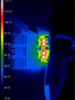
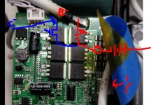
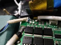
I noticed there are 4x 10Ohm (edit 10mOhm) resistors, and those were getting really hot. Even with just 40A, they reached 130C in about 1 minute with the battery outside the enclosure.
I wanted to see if I could push it higher than 40A for "short periods", and hopefully modify the most limiting components.
What parts should I check for?
I started tweaking my controller, increasing the battery limit, but the BMS never shut the battery off. I went all the way to 70A and the battery kept running for about a minute without shutting off.
The 14gauge discharge wires were getting hot (over 100C), so I started replacing those with 10gauge.
I noticed there are 4x 10Ohm (edit 10mOhm) resistors, and those were getting really hot. Even with just 40A, they reached 130C in about 1 minute with the battery outside the enclosure.