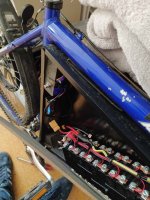
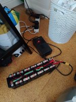
BMS not charging or discharging

I don't see what you see, Molfped. I see the two red wires on the XT connectors changing to green and then connecting to the last terminal (B+ ?) but I could be seeing what I expected to see, and you probably have a better eye.

By the way, is that an XT90 for discharge and an XT60 for charge? I killed a 36V battery last year when I put 48V into the charge side.
 
docw009 said:
I don't see what you see, Molfped. I see the two red wires on the XT connectors changing to green and then connecting to the last terminal (B+ ?) but I could be seeing what I expected to see, and you probably have a better eye.

By the way, is that an XT90 for discharge and an XT60 for charge? I killed a 36V battery last year when I put 48V into the charge side.

Sorry docw009 I misread his first post. The main battery - has to connect to the B- on the bms for it to work. It appears that has not been done.


Sent from my iPhone using Tapatalk
 
Molfped said:
The main battery - has to connect to the B- on the bms for it to work. It appears that has not been done.

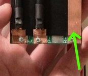
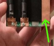
I mentioned in a previous post, there are 4 pads and 3 labels. So it's difficult to tell which side of the label to attach the wire. LHS or RHS of the "B-" label.

_20200210_204803.JPG


Can you look on the circuit board and trace where the 2 pads on either side of the "B-" label go? Maybe the battery negative should be connected on the LHS of the label, not the RHS?
 
Right hand side. Needs a cable from battery negative to there. Another cable. Not either of the others already connected.


Sent from my iPhone using Tapatalk
 
Molfped said:
Right hand side. Needs a cable from battery negative to there. Another cable. Not either of the others already connected.

Kinda like the big copper strip that already connects the battery negative to the RHS pad ?

_20200210_204803.JPG
 
serious_sam said:
The "generic" Chinese bluetooth BMSs are good value.

You can adjust a lot of the parameters, calibrate the voltage for each series channel down to 1mV, and monitor the pack/cell voltages and temperatures with a smartphone.

They are more expensive than the one you have though.

https://endless-sphere.com/forums/viewtopic.php?f=14&t=88676

Thanks serious_sam, If I don't get this working I might look into that.

docw009 said:
The connectivity shown in KevMCA's pictures make sense to me. Might be a problem with the copper strips screwed down to solder pads passing current. Could be oxidation on both surfaces. Did he pull the balance connector and measure the balance voltages at the connector, using pins?

Thanks docw009, I thought it could have been a problem with connectivity between the cells alright. I filed down each of the copper strips and tightened them down good and tight to get good contact. That being said, there could still be an issue.

I pulled the balance connector and checked each voltage from the connector. Then I plugged it into the BMS and measured at the PCB and they were the same as previously stated.

docw009 said:
What happens if he bypasses the BMS to see if the pack can run the ebike. Connect an XT connector across the battery and the B- terminal. See if bike runs. If it does, it also should charge across that plug, but for safety just check it briefly. That will test the integrity of the cell connections.

I think I've put in about a half dozen different BMS cards, bought about 10 of them, and the only ones I ever saw not work were made by JBD. They had ON/OFF circuits that didn't work.

Very good idea! I'm going to do this next. I thought of doing this before, but was too lazy and forgot about it XD I wouldn't be surprised if that was the issue. I'm using home built NESE modules. I printed them myself and made the nickel strip connectors myself, so there could be an issue there alright.

docw009 said:
I don't see what you see, Molfped. I see the two red wires on the XT connectors changing to green and then connecting to the last terminal (B+ ?) but I could be seeing what I expected to see, and you probably have a better eye.

By the way, is that an XT90 for discharge and an XT60 for charge? I killed a 36V battery last year when I put 48V into the charge side.
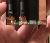
That's exactly how I have the positive connected up. Also yes, the XT60 connector is for charging and the XT90 is for discharging so I don't get them mixed up.
 
I don’t see anything other than the small wire in the harness. The main pack negative that will carry all of the current needs to connect to that buss bar so that the bms can function properly. The reason that connection has the big copper bar is to carry the total current of the load. Otherwise, heat would destroy the bms. There is probably a shunt on the end that you should connect to. I can’t tell from your pics because it appears that the B- bar wraps around to the other side. On mine the shunt looks like a hump just behind the connection point. I’ll post a picture from my computer.


Sent from my iPhone using Tapatalk
 
serious_sam said:
Molfped said:
The main battery - has to connect to the B- on the bms for it to work. It appears that has not been done.

I mentioned in a previous post, there are 4 pads and 3 labels. So it's difficult to tell which side of the label to attach the wire. LHS or RHS of the "B-" label.

Can you look on the circuit board and trace where the 2 pads on either side of the "B-" label go? Maybe the battery negative should be connected on the LHS of the label, not the RHS?

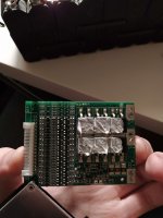
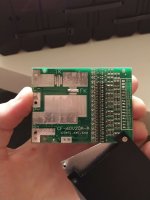
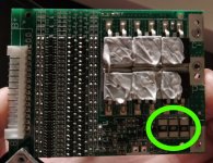
I believe it is the side closest to the edge of the board. These two images show the front and back of the board. As you can see, the pad on the left of the B- sign is only on the back and not the front.

IMG_20200208_183125 (1).jpg
IMG_20200208_183056 (1).jpg
 
Molfped said:
I don’t see anything other than the small wire in the harness.

I don't know what that means exactly.

Molfped said:
The reason that connection has the big copper bar is to carry the total current of the load. Otherwise, heat would destroy the bms.

That big copper bus bar connected at B- on the BMS connects straight to the negative side of the battery pack. I don't know what you mean by the heat would destroy the BMS though :|

Molfped said:
There is probably a shunt on the end that you should connect to. I can’t tell from your pics because it appears that the B- bar wraps around to the other side. On mine the shunt looks like a hump just behind the connection point. I’ll post a picture from my computer.

There's no shunt, which I assume you mean a current shunt for some current measurement or something?
 
KevMca said:
I believe it is the side closest to the edge of the board. These two images show the front and back of the board. As you can see, the pad on the left of the B- sign is only on the back and not the front.

I agree, I think you are correct.

Sorry I don't have any more suggestions.
 
Molfped said:
Show me the connection. I don’t see it.

That copper bar was added by KevMca. It is the connection from the battery negative to the B- pad. It isn't an original part of the BMS.
_20200210_204803.JPG
 
Added? So where is it connected to the pack negative? Still don’t see a connection other than sense - on 1st pin of the bms harness.


Sent from my iPhone using Tapatalk
 
Molfped said:
Added? So where is it connected to the pack negative? Still don’t see a connection other than sense - on 1st pin of the bms harness.

Please refer to here v

KevMca said:
Molfped said:
The reason that connection has the big copper bar is to carry the total current of the load. Otherwise, heat would destroy the bms.

That big copper bus bar connected at B- on the BMS connects straight to the negative side of the battery pack. I don't know what you mean by the heat would destroy the BMS though :|

I can't send a photo because I'm not near the battery.
 
docw009 said:
What happens if he bypasses the BMS to see if the pack can run the ebike. Connect an XT connector across the battery and the B- terminal. See if bike runs. If it does, it also should charge across that plug, but for safety just check it briefly. That will test the integrity of the cell connections.

I tried this. It ran the ebike no bother at all! It ran the motor with no sign of struggling in any way. I also plugged into the charger and it charged away there for a minute or two. So from that, I'm pretty sure it's not an issue with the battery.

So it's definitely an issue with the BMS alright.

Webp.net-compress-image.jpg
Webp.net-compress-image (1).jpg
 
I am using 20s 60 amp bms it was working fine. Full charger @ 83.4 and Cutoff volt was 60.
Battery pack got water damaged bms was completely dry.
Now problem I am facing it the bms cutoff @ 70 volt. It is charging to full
After cutoff when switch to directly bypassing bms it is working..
So what could be possible problem?
 
Hi,

I saw this post and wanted to chime in… I even registered just to make this comment, lol!

Anyway, I know this thread is old and this reply is coming a bit late but I just wanted to mention that many BMS charging circuits require that a charging voltage be applied to the P+ and P- for several seconds for the BMS to allow discharging.

Note: This only needs to be done once unless some sort of error occurs in the wiring such as a short circuit or what not. So on a brand new BMS you only need to initially start a charge for a few seconds and then it will function (and allow the BMS to discharge through the P+ and P-) provided nothing goes wrong with the batteries or wiring.

Considering how widely this is used in BMS systems I think it is some sort of safety feature.

I scanned through all the messages and I did not see anyone mentioned the above, however, my apologies if someone already suggested this.
 
Back
Top